
1. Spresense board overview
The Spresense project consists of a Arduino compatible board with Sony’s high performance CXD5602 micro-controller. The CXD5602 has built-in GPS and high-resolution audio capabilities.
This section outlines the Spresense hardware and software in the following two chapters:
To start programming the Spresense directly see the Getting started guides for the two available SDKs:
For further information on CXD5602, please refer to the following.
2. Spresense Hardware
2.1. Spresense Board
This section describes the Spresense hardware.
Spresense consists of the following boards:
It is also possible to design your own
The main board uses a processor developed by Sony for IoT and sensing applications. The main board can be operated alone or with the extension board.
The Spresense uses Sony’s new chipset on the main board:
The Spresense extension board is a board which extends the interfaces compared to the Spresense main board. The Spresense main board and the Spresense extension board are connected by a Board-to-Board (B-2-B) connector. The Spresense extension board has Arduino Uno pin compatible shape and pin socket locations. However, there are some differences compared to the Arduino Uno. For details, please refer the Differences between Spresense and Arduino Uno.
The Spresense main board and Spresense LTE extension board are connected by a Board-to-Board (B-2-B) connector, and the Spresense LTE extension board supports the LPWA standards LTE-M and NB-IoT. It enables information from sensors to be transmitted using the LTE-M or NB-IoT network.
2.1.1. Main board
The Spresense main board has the following features.
-
Sony’s CXD5602 Processor
-
8 MB Flash memory
-
PCB with small footprint
-
Dedicated camera connector
-
GNSS (GPS) antenna
-
Pins and LEDs
-
Multiple GPIO (UART, SPI, I2C, I2S)
-
2 ADC channels
-
Application LED x 4 (Green)
-
Power LED (Blue)
-
USB serial port
-
|
All Spresense main board pins operate at 1.8V. Connecting the main board pins to higher voltage can cause permanent damage. |
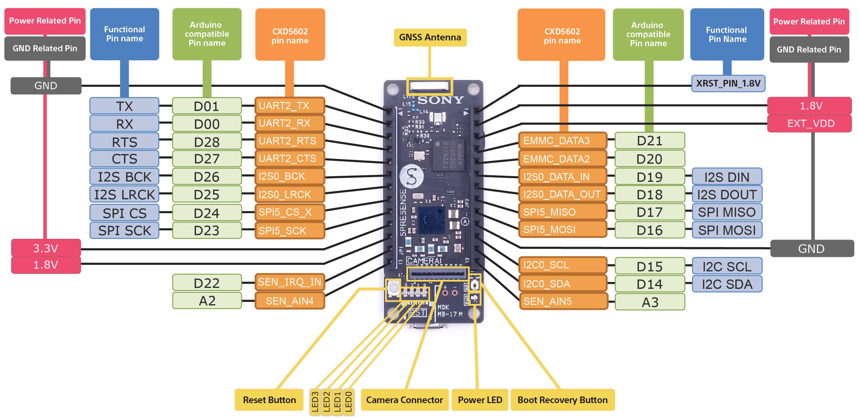
The name and location of connectors, LEDs and switches on the main board are shown below.
| Name | Description |
|---|---|
[PWR] Power LED |
Power LED. Emits blue light when power is supplied. |
[RST] Reset button |
Reset button. |
[LED0] to [LED3] |
Four user controllable green LEDs. |
[CN2] |
Micro USB Type-B connector. |
[CN4] |
100 pin B-2-B connector to interface to additional boards. This connector is on the underside. |
[CN5] |
Camera connector. |
[BR] Boot recovery button |
This is used when restoring to the factory reset state. Only for recovery, normally not needed. |
The following schematic block diagram shows the main board design:
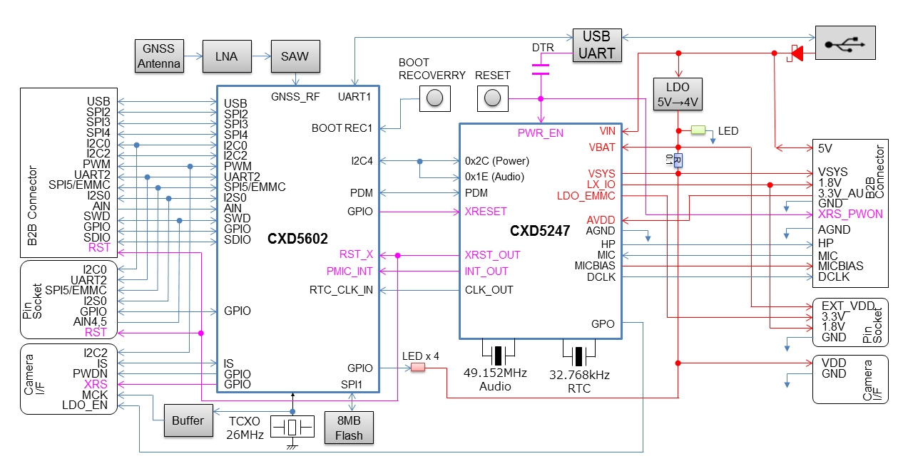
PDF file of the main board circuit diagram can be obtained from the following link.
2.1.2. Extension board
The Spresense extension board has the following connectors in addition to Arduino Uno compatible pin sockets.
-
3.5 mm headphone jack
-
Micro SD card
-
An extra USB port
-
Multiple microphone pins
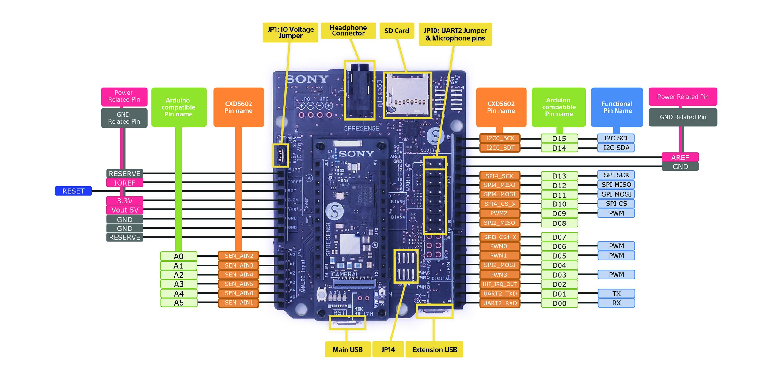
The extension boards configuration is set by jumpers.
| Name | Description |
|---|---|
CN3 |
100 pin B-2-B connector for the main board. |
CN4 |
Micro SD card. |
CN6 |
Micro USB Type-B connector. It can provide USB MSC (Mass Storage Class) function allowing access to the SD card on the extension board directly from the PC. |
CN7 |
Headphone 3-pole 3.5mm jack. |
JP1 |
GPIO voltage can be set to 5V or 3.3V by using a jumper on JP1. A standard 2.54mm pitch jumper should be used. This one will be supplied with the extension board. |
JP10 - pins 3 to 16 |
Microphone connector. These pins connect analog or digital microphone. Please refer How to use microphones for details. |
JP10 - pins 1 and 2 |
You can disable UART2 on the extension board by closing pin 1 and 2 on JP10. This allows UART2 on the main board to be used at 1.8V I/O. No jumper is shipped with the extension board, a 2.54 mm pitch jumper should be used. |
JP14 |
Jumpers to support digital microphones on JP10. Please refer How to use microphones for details. |
microSD |
The micro SD card that can be used with the Spresense extension board must be formatted in FAT32. The only "SDHC" micro SD card is formatted with FAT32 at the time of shipment from the manufacturer. For cards formatted with other file systems, format them in FAT32 using a formatting tool for SD cards in a PC etc. beforehand. |
The following block diagram shows the extension board design.
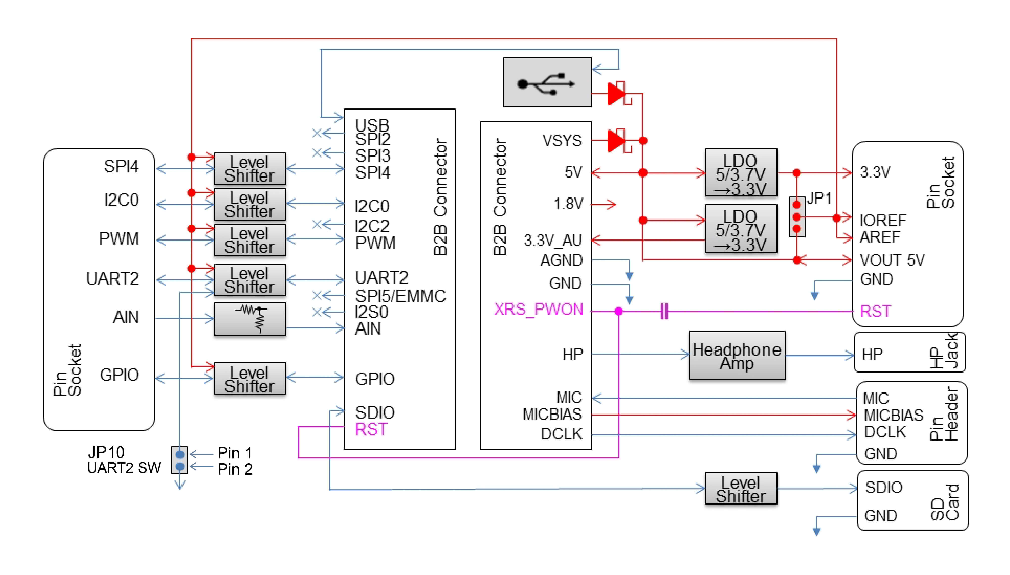
PDF file of the extension board circuit diagram can be obtained from the following link:
2.1.3. LTE extension board
Spresense The LTE extension board can communicate using the LTE-M network. Equipped with a headphone jack, microSD card slot, and microUSB terminal.
Also, although the number of systems is reduced compared to the Spresense extension board, it is equipped with pin headers for microphone input, digital input/output, and analog input.
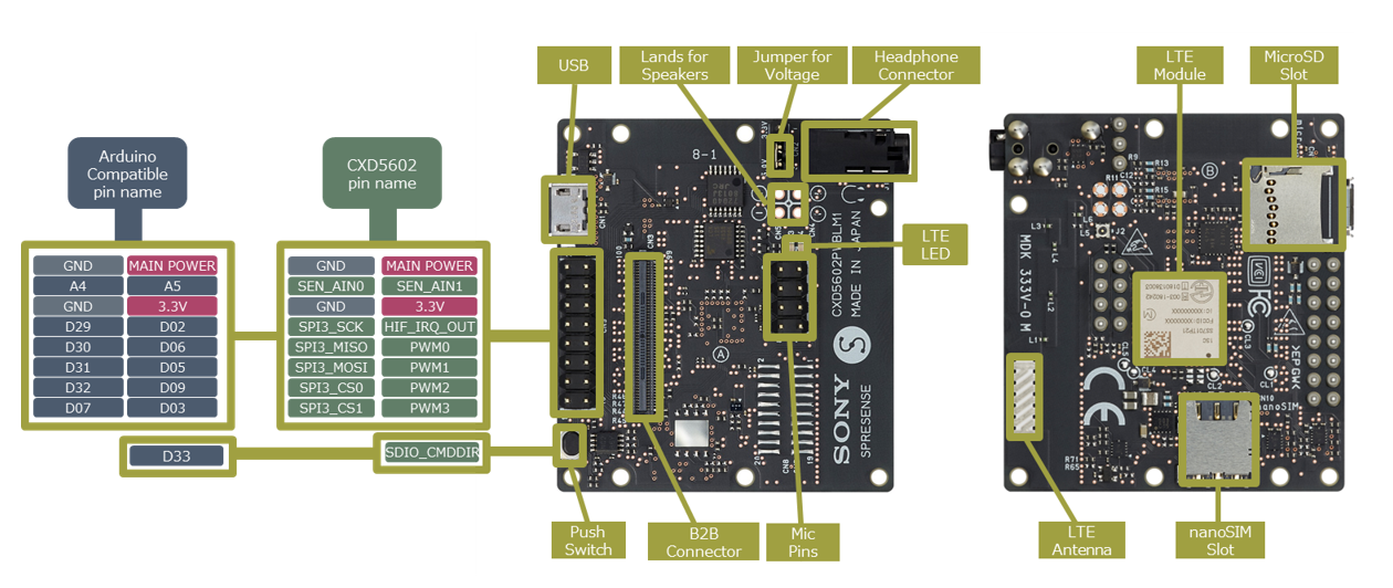
The names on the circuit such as connectors and switches placed on the LTE extension board are shown below.
| Ref | Name | Description |
|---|---|---|
ANT1 |
LTE module |
An LTE transmission/reception module compatible with LTE Cat-M1. |
CN4 |
LTE antenna |
Onboard chip antenna. |
CN10 |
nanoSIM connector |
Connector for mounting nanoSIM. |
CN1 |
microUSB connector |
A microUSB Type-B connector for supplying power to this board. You can access the SD card of the extension board directly from your PC using the MSC (Mass Storage Class) function of USB. |
CN3 |
BtoB connector |
A connector for connecting to the Spresense main board. |
CN2 |
I / O power setting jumper |
A jumper that sets the voltage level of the CN9 digital signal to 5V or 3.3V. The factory default I / O voltage is set to 5V. |
CN9 |
Signal pin header |
A 2.54mm pitch pin header for connecting external devices. |
CN7 |
microSD connector |
Connector for inserting a microSD card. |
J1 |
Headphone jack |
A headphone jack compatible with a φ3.5 mm 4-pole mini plug. You can use a headset with stereo headphone output + monaural microphone input. Of course, you can also use 3-pole stereo mini jack headphones. |
CN6 |
Pin header for mic |
A 2.54mm pitch pin header for connecting a microphone. |
D4 |
LTE LED |
An orange LED that indicates the LTE communication status. |
S1 |
Push switch |
It is a general-purpose switch. When you press the switch, the signal changes from High level to Low level. It is assigned to D33 (“SDIO_CMDDIR” pin of CXD5602) of Arduino IDE. |
CN4 |
Pin header for speaker (L) |
Pin header for speaker (L) (not mounted at the time of shipment).。 |
CN5 |
Pin header for speaker (R) |
Pin header for speaker ® (not mounted at the time of shipment). |
CN8 |
Connector for CoreSight 20 |
Pin header for SWD (not mounted at the time of shipment). |
The block diagram of the LTE extension board is shown below. VSYS in the figure is 4V when power is supplied from the USB terminal.
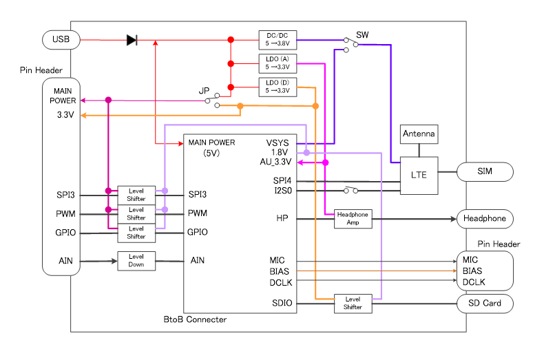
A PDF of the LTE extension board schematic is available at the following link:
2.1.4. Camera board
The Spresense camera board has the Sony ISX012 image sensor mounted together with a lens. The Sony ISX012 has an effective pixel count of 5.11M pixels and an onboard encoder that can acquire pictures in JPEG, Y/C or RGB format.
| Image sensor | |
|---|---|
Sensor type |
1/4 type CMOS image sensor |
Effective pixel |
5.11M pixels 2608(H)×1960(V) |
Recording pixel |
5.04M pixels 2592(H)×1944(V) |
Camera control |
|
ISO sensitivity |
ISO 40~800 |
Scene selection |
12 preset |
Exposure control mode |
Auto, Shutter priority, ISO sensitivity priority, Long time AE |
Photometry |
Multi pattern, Center weight, Average, Spot |
Exposure compensation |
±2EV, 1/3 EV steps |
Shutter speed range |
1/8 s (long AE mode) to 1/42000 s |
White balance setting |
Auto, Daylight, Cloud, Fluorescent, Lamp |
Picture format |
|
Output still picture format |
JPEG(4:2:2), Y/Cb/Cr, YUV, RGB, JPEG+YUV(thumbnail) |
Still data rate |
5M pixel 15 frame/s JPEG output |
Movie data rate |
SVGA 30 frame/s YCbCr output |
HD movie support |
1080p(1920×1030 30 frame/s), 720p(1208×720 60 frame/s) |
In addition, the following table is the specification of the lens.
| Function | Spec |
|---|---|
Lens type |
1/4 inch 4 pieces |
Effective focal length |
2.74mm |
F-number |
2.0±5% |
Field of view |
78°±3° |
Chief ray angle |
<33.5° |
Distortion |
<1.5% |
Image quality |
Center 1100 lines, Near the corners 900 lines |
Focus distance |
1.5m |
Focusing range |
77.5 to 237.06cm |
PDF file of the camera board circuit diagram can be obtained from the following link:
2.1.5. HDR camera board
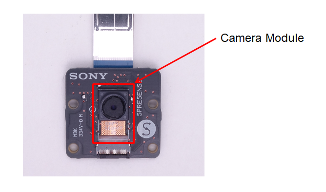
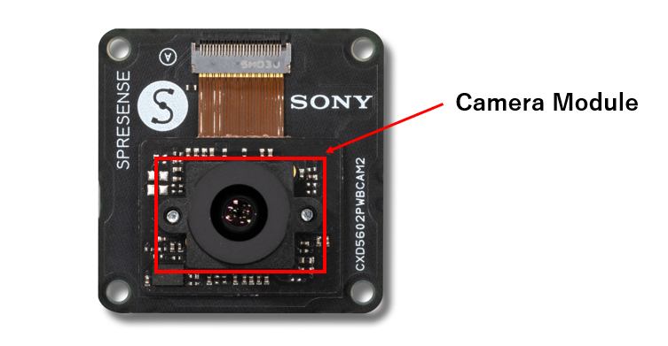
The Spresense HDR camera board has a camera module. This camera module consists of Sony image sensor ISX019 and lens.
The Spresense HDR camera board is equipped with an FPGA and a color space conversion circuit and a JPEG encoder, so in addition to Y / Cb / Cr, send RGB and JPEG format images to Spresense.
The specification table of ISX019 for Spresense HDR camera board is shown below.
| Image Sancer | |
|---|---|
Sensor type |
1 / 3.8-inch CMOS image sensor |
Effective pixel count |
1.26 million pixels 1297 (H) x 969 (V) |
Recommended number of recording pixels |
1.23 million pixels 1280 (H) x 960 (V) |
Camera control |
|
Photometry |
Average, center weight, spot, histogram |
Exposure compensation |
± 2EV, 1 / 3EV steps |
White balance setting |
Auto, MWB mode, user mode, one-push mode |
Exposure time adjustment |
Variable |
Image format |
|
Output image format |
Y / Cb / Cr |
High Dynamic Range (HDR) Function |
|
HDR function |
Digital Overlap (DOL) method / internal synthesis |
In addition, the specifications table of the lens is described below.
| Functions | Performance |
|---|---|
Lens configuration |
6 glass lenses |
IR cut filter |
415-650nm (visible light transmission) |
Lens diameter |
M8 P0.35 |
Effective focal length |
5.1mm ± 5% |
F-number |
2.0 ± 5% |
Field of view |
Vertical: 31.2 °± 5%, Horizontal: 41.8 °± 5%, Diagonal: 52.4 °± 5% |
Chief ray angle |
<17.5 ° |
Distortion |
-1.36% |
Resolution |
Over 500 |
Focus distance |
Adjustable |
Focusing range |
2cm ~ ∞ |
A PDF of the camera board schematic is available at the following link:
2.1.6. GNSS Add-on board
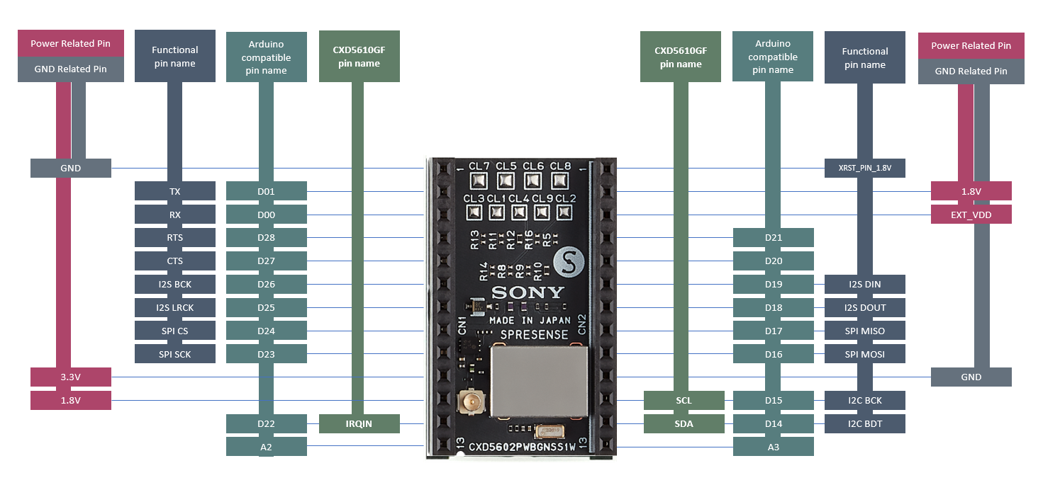
The Spresense GNSS Add-on board is equipped with Sony Semiconductor Solutions' GNSS receiver LSI "CXD5610GF" that achieves dual-band positioning using the L1 and L5 bands. Highly accurate and stable positioning is possible even in harsh environments such as reflections from the ground or nearby buildings.
The Spresense GNSS Add-on board does not have an antenna for GNSS. A separate external antenna is required.
| Supported GNSS | GPS/Galileo/BeiDou/GLONASS/QZSS/SBAS/NavIC |
|---|
A PDF of the GNSS Add-on board schematic is available at the following link:
2.2. Custom Board
The B-2-B connector can be used to interface to your own custom board, rather than the Extension board.
For details of mechanical and power supply requirements see the add on board design guidelines
For details of the B-2-B connector pinout and functions see the schematics of Spresense main board
Your custom board may replicate some of the features from the Extension board which you can copy from the schematics of Spresense extension board.
2.3. How to use Spresense board
2.3.1. How to fit a shading seal on the main board/HDR camera board
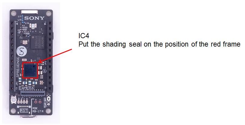
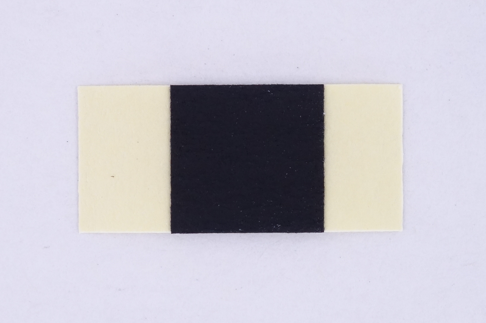
A shading seal is provided with the kit and should be mounted on IC4 in Spresense main board before it is used. The location of where to fit the seal is shown in the picture.
A shading seal is provided with the kit and should be mounted on IC10 in Spresense HDR camera board before it is used. The location of where to fit the seal is shown in the picture.
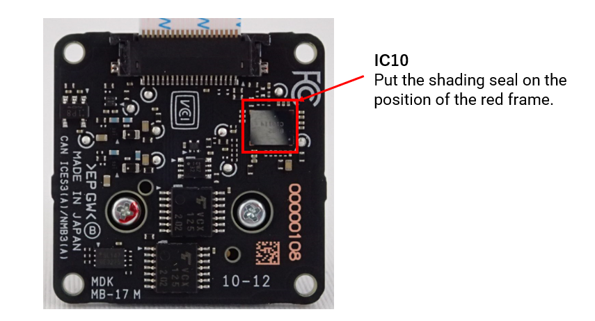
| Malfunction might occur if the board is placed under direct or in the proximity of a strong light source, e.g. sunlight or a bright lamp if no shading seal is mounted. |
| Vendor | Model |
|---|---|
Shurtape |
CP-743 |
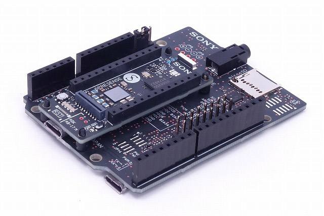
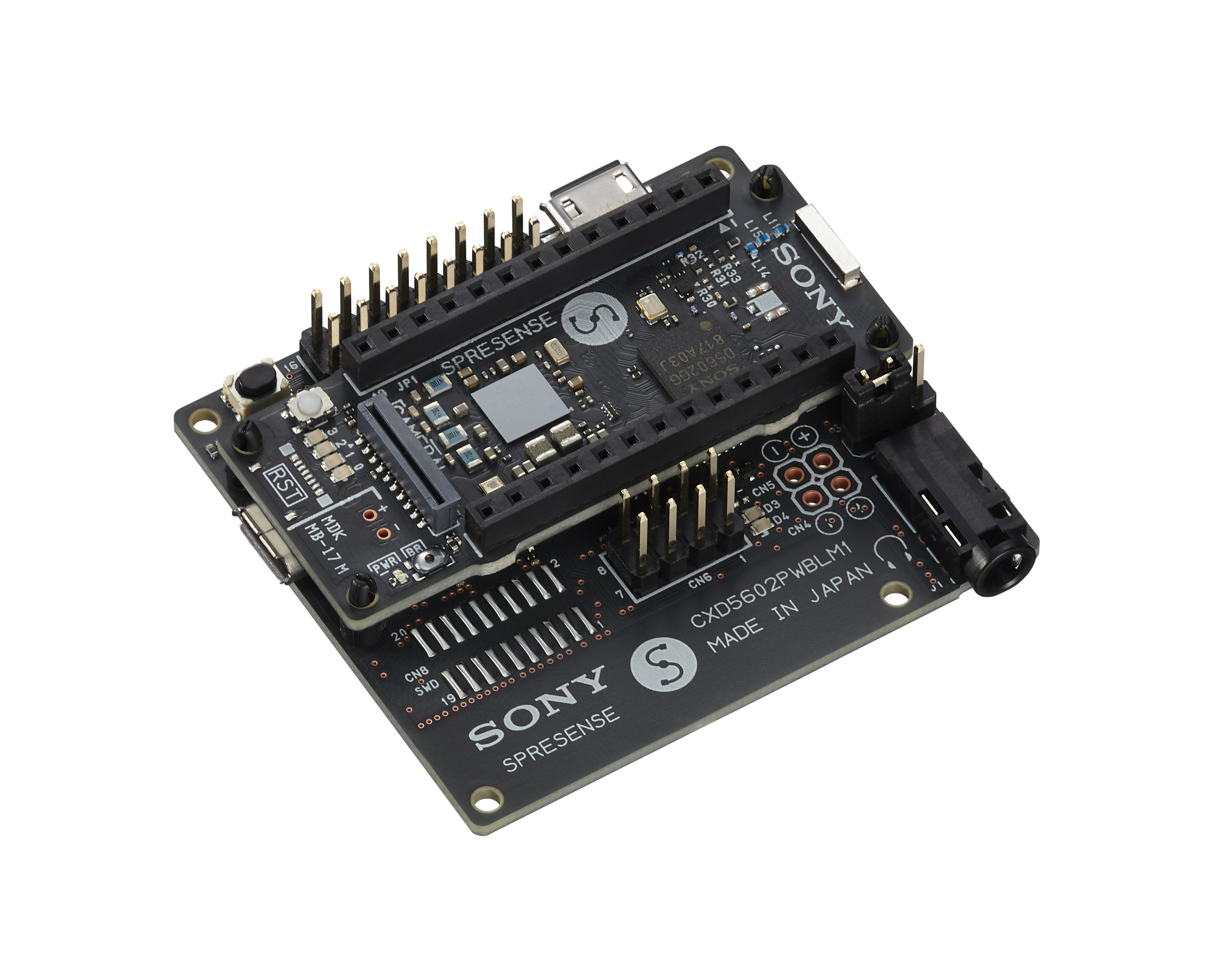
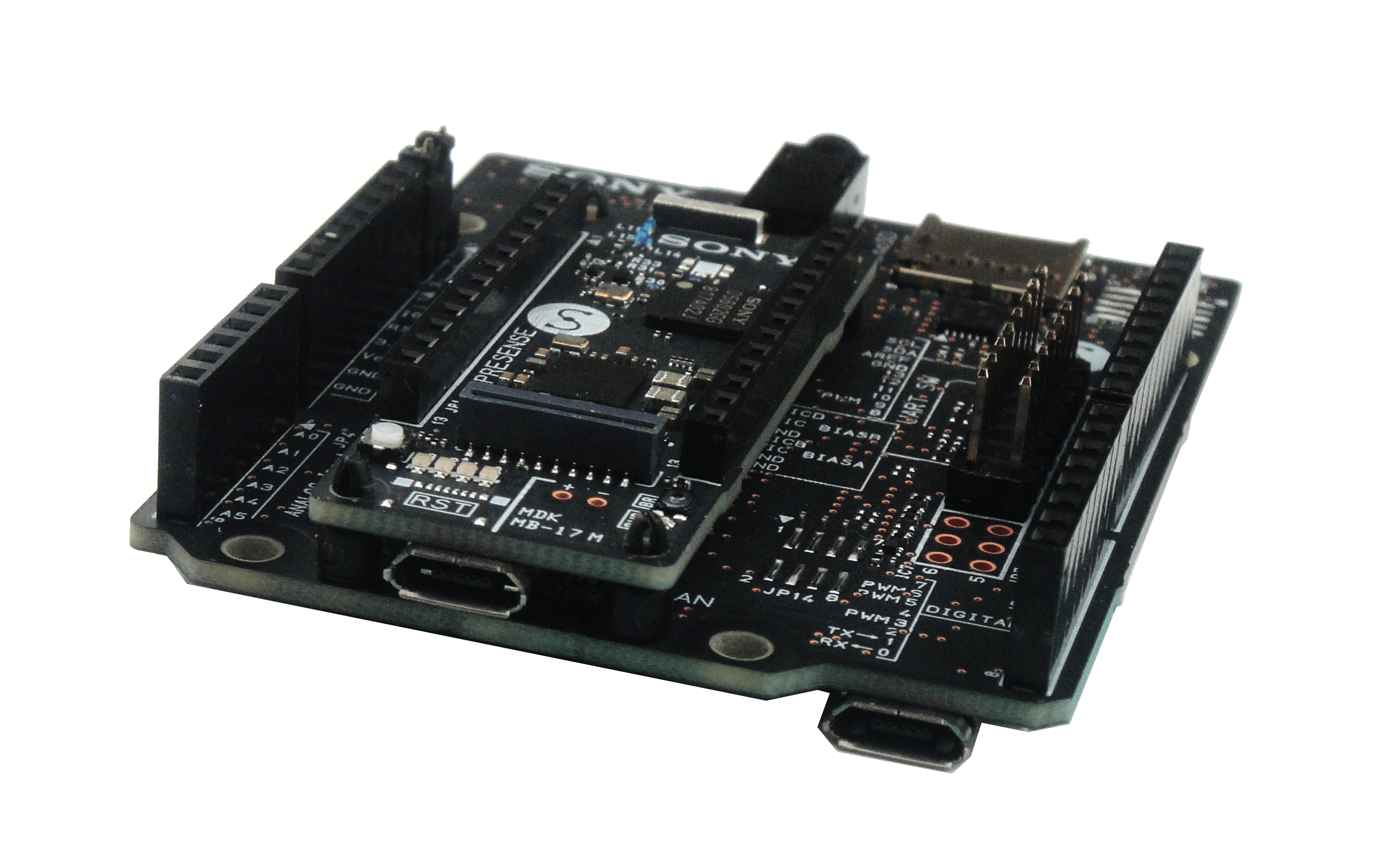
2.3.2. How to attach the Spresense extension board and the Spresense main board
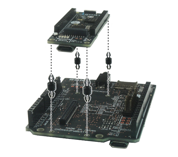
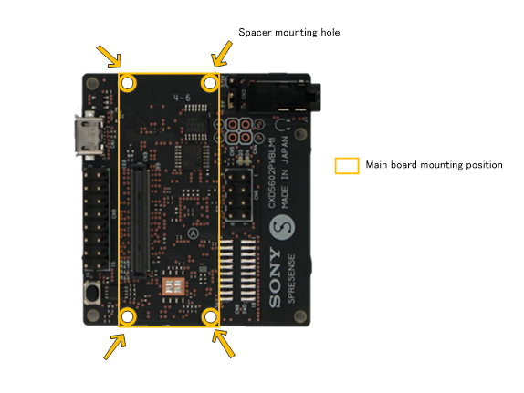
This section explains how to install the Spresense extension board and the Spresense main board. The package of the Spresense board has 4 spacers to attach the Spresense main board.

These spacers are put in to the through-holes on the Spresense extension board. Please note the positions of the through-holes.

After putting in the spacers on the Spresense extension board, attach the Spresense main board.
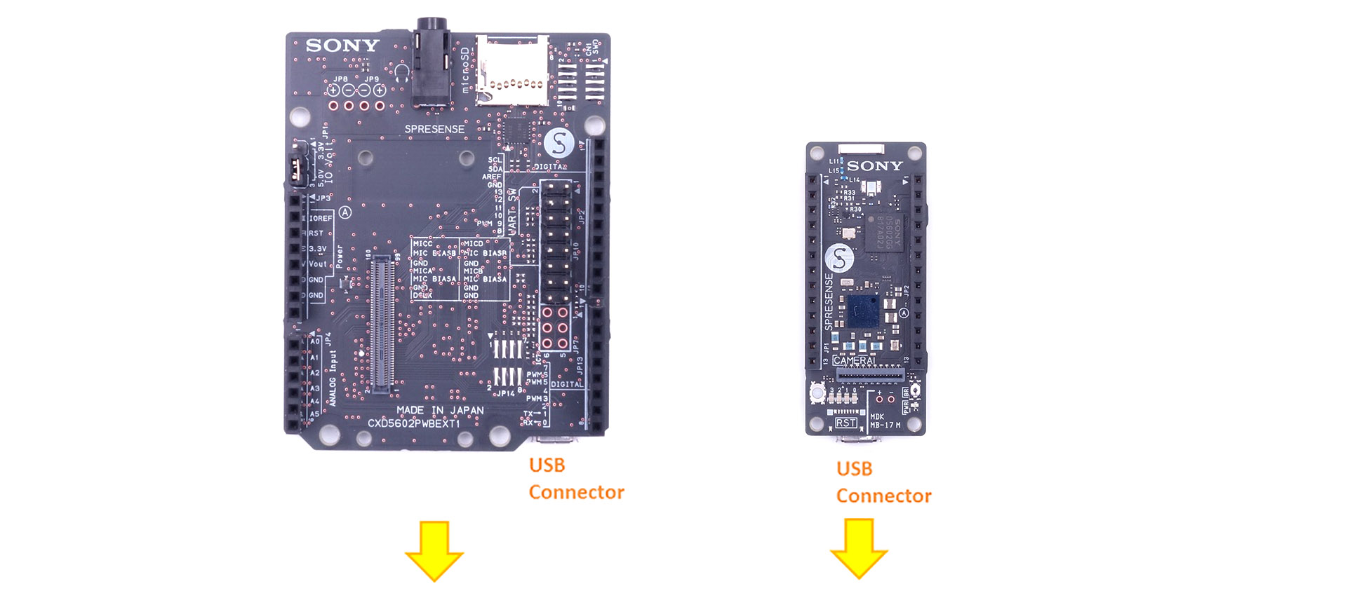
The USB connectors face the same direction. On this picture the Spresense main board and the Spresense extension board have been mounted.
Please confirm the mating of the B-2-B connector by pressing the Spresense main board and Spresense extension board from the top and bottom again after completing the installation etc. Please note that the function on the Spresense extension board such as the micro SD card and the audio function may not work if the mating is incomplete.
| When attaching/detaching the main board and extension board, be careful not to apply partial load. |
2.3.3. How to connect the Spresense main board to the Spresense LTE extension board
This section describes how to install the Spresense main board and the Spresense LTE extension board.
| Be sure to turn off the power before connecting the main board and LTE extension board. |
The Spresense LTE extension board comes with four spacers to connect to the main board.
Insert the spacers into the through holes of the Spresense LTE extension board. Pay attention to the location of the holes.
If any of the LTE extension board functions, such as the micro SD card or various audio functionality, do not work or seem to work improperly, the BtoB connector may be incompletely fitted. Hold the main board and LTE extension board between your fingers from the top and bottom, and try connecting them again.
2.3.4. How to connect and prepare the Spresense main board and Spresense camera board
This section explains how to attach the Spresense camera board to the Spresense main board.
| Since the camera module is very sensitive to static electricity it is advised to discharge any static electricity from the body before handling the camera module. This can be done by touching a grounded part, like a grounded computer chassis. Static electricity can cause the camera module to malfunction. |
The camera module is connected to the main board (CN5) via a flat cable. The picture below shows how the flat cable is supposed to be mounted. The flat cable can only be inserted in one way to work so it is important to take note on which side it should be connected on.
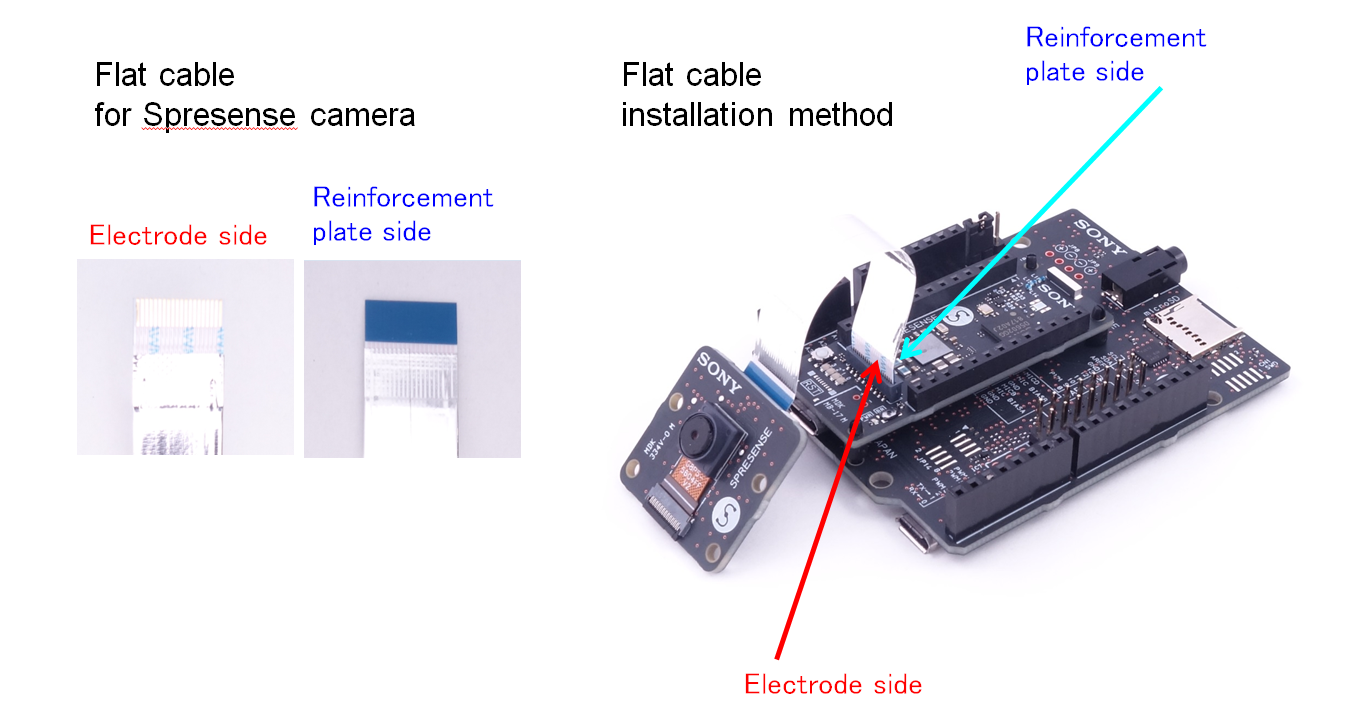
The lens of this camera is covered with a small translucent blue plastic film. This is for protection, please remove it before use. Please be gentle when removing the protecting plastic film.
2.3.5. About the flat cable on the Spresense camera/HDR camera board side
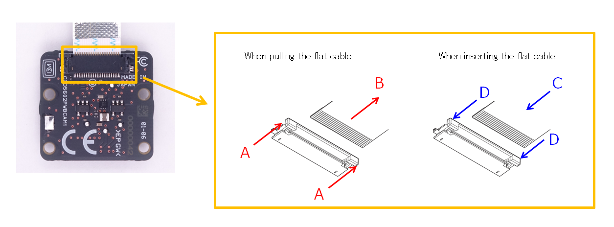
The flat cable connector on both the camera/HDR camera board and main board is rather fragile it is advised not to insert/remove the cable more than necessary.
Please follow the instructions below when inserting/removing the flat cable.
-
When pulling out the flat cable:
-
A. Apply a uniform force to both sides of the lever of the connector, slide the lever slowly and horizontally and pull it out horizontally.
-
B. Pull out the flat cable.
-
-
When inserting the flat cable
-
C. Insert the flat cable firmly into the connector. The electrode side of the flat cable should be facing away from the PCB. See image below.
-
D. Apply a uniform force to both sides of the lever of the connector and slide the lever slowly horizontally and push it in parallel with the board.
-
| Please operate the lever of the connector of the camera/HDR camera board slowly and carefully. If you apply uneven force to sides of the lever or move it in an other than horizontal direction with respect to the board you might damage the lever. |
Also, the flat cable that can be used as a substitute when the flat cable for the camera/HDR camera is damaged is shown below. Below is list of replacement flat cables, it is advised to use a flat cable as short as possible.
| Vendor | Model | Length |
|---|---|---|
Molex |
15166-0211 |
102mm |
Molex |
15166-0213 |
127mm |
Wurth Electronics |
687620100002 |
100mm |
2.3.6. How to connect and prepare Spresense main board and Spresense GNSS Add-on board
This section describes how to install the Spresense GNSS Add-on board to the Spresense main board.
Align the 1st pin of JP1 and JP2 of the Spresense main board with the 1st pin of CN1 and CN2 of the Spresense GNSS Add-on board, and push it lightly. If the orientation is correct, the letters "SONY" on the Spresense main board and the Spresense GNSS Add-on board will have the same orientation.
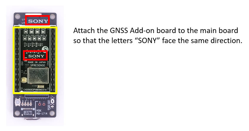
WARNING:When attaching the Spresense GNSS Add-on board to the Spresense main board, be sure to adjust the position so that the pins of the GNSS Add-on board’s pin sockets fit straight into the pin sockets on the main board, and then lightly press the GNSS Add-on board with your hand. If you try to insert the pin at an angle or push it too hard, the connector may be damaged.
When removing Spresense the GNSS Add-on board from the Spresense main board, use a commercially available board removal jig (IC removal jig), etc., carefully.
| Failure to use the board removal jig may damage the pins on the Spresense GNSS Add-on board connector. |
| CN1 and CN2 on the Spresense GNSS Add-on board are socket type connectors. Various Spresense Add-on boards can be installed on top of it. |
In addition, since the CXD5610 GNSS receiver LSI has a built-in MRAM, if it is brought close to something that emits a strong magnetic field such as a magnet, the data stored in the MRAM may be erased and it may not work properly.
| Spresense GNSS Add-on board should not be brought close to objects that generate strong magnetic fields such as magnets. |
2.3.7. How to connect and prepare Spresense GNSS Add-on board and GNSS antenna
This section describes how to attach the GNSS antenna (sold separately) to the Spresense GNSS Add-on board. The GNSS antennas whose operation has been confirmed are shown below. Please note that the Spresense GNSS Add-on board does not have an LNA, so only active antennas can be used, passive antennas cannot be used.
| Vendor | Model | Connection |
|---|---|---|
ABRACON |
APARC2511X-SG3L5 |
U.FL |
Tallysman Wireless |
33-8825-00-3000 |
SMA |
TAOGLAS |
AA.200.151111 |
SMA |
TAOGLAS |
AA.178.301111 |
SMA |
Beitian |
BN-345AJ |
SMA |
Ublox |
ANN-MB1-00-00 |
SMA |
Unictron |
H2MA003D100100 |
SMA |
2J-antenna |
2J7C01MC3F-300LL100-C20NST |
SMA |
Jinchang Electron |
JCA231 |
SMA |
Jinchang Electron |
JCA236D |
SMA |
Amotech |
AGA556022-S0-A17 |
U.FL |
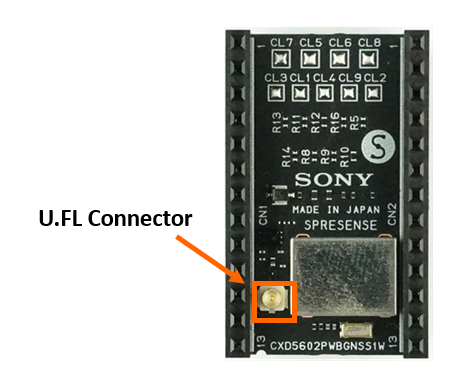
Attach a GNSS antenna with a U.FL connector (male) cable to the U.FL connector (female) on the Spresense GNSS Add-on board.
When using a GNSS antenna with an SMA connection, prepare a U.FL (male)-SMA (female) conversion cable as shown below.
| Vendor | Model |
|---|---|
Hirose |
HRMJ-UFLHF6-04N2TV-A200RS |
| Be careful when connecting or disconnecting the antenna to the U.FL connector. If you try to join the connector at an angle or apply a strong force, the connector may be damaged. |
| Do not put a load on the cable while the antenna cable is connected to the U.FL connector. U.FL connector may be damaged. |
2.3.8. Powering the Spresense Board
There are several ways to power the Spresense boards:
-
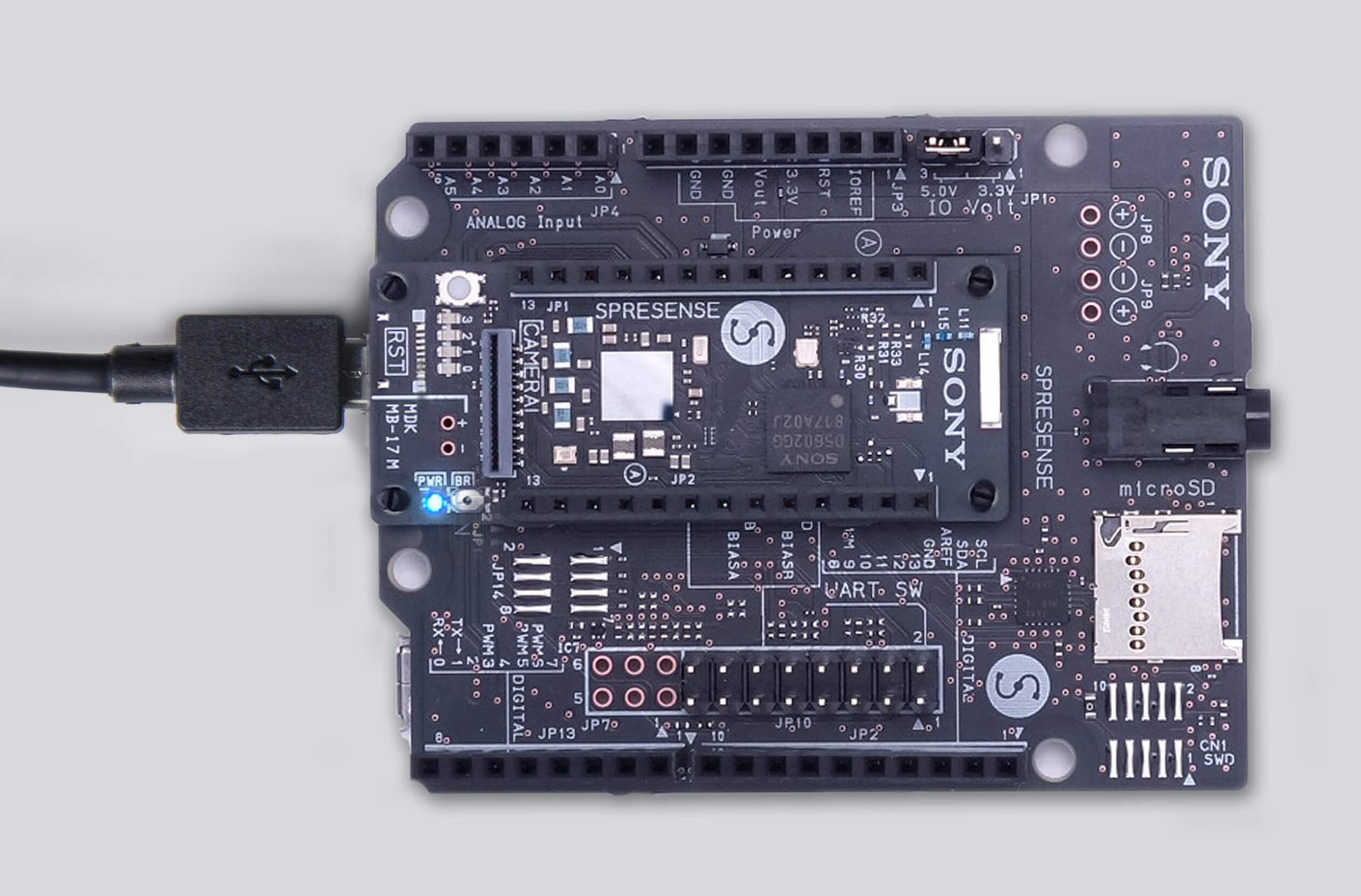
Use the main board’s micro USB connector. Simply connect your PC to the micro USB connector on the main board to get started. It will power the main board alone, or the main board and extension board as a set. This is the preferred method for most development. The main board USB is intended for serial port applications only.
-
When supplying power via the micro USB connector, use a micro USB cable that is as thick and short as possible.
| Powering the Spresense board using a conversion adapter for USB Type-C AC adapter etc. to microB may result in a voltage exceeding the VBUS withstand voltage, which may destroy the Spresense board. (Conversion adapters with Type-C receptacle connectors are non-USB standard compliant). |
|
The Spresense can be powered by a USB battery pack. Some USB battery packs require a minimum load current and Spresense may take less than this current, which will cause the USB battery pack to turn off after a few seconds. For reliable USB battery pack operation choose a battery pack that has an "always on" feature or use a USB "keep-alive load". |
2.3.8.1. When using the Spresense extension board
-
You can use the micro USB connector on the main board or the micro USB connector on the extension board to power your Spresense system. It is designed so that it is safe to supply power from the micro USB connectors on both sides at the same time.
-
You can set the micro USB port on the extension board as a USB device in MSC (Mass Storage Class) mode. This allows you to think of the SD card on the extension board as a storage device for your PC.
-
In addition, by supplying 5V ± 0.25V to the VOUT pin of the extension board, it is possible to supply power from other boards. However, if you connect a power supply with a voltage outside the range of 5V ± 0.25V, power circuit may be destroyed, so handle with care. If this power supply and power supply from the micro USB connector are performed at the same time, insert a backflow prevention circuit into the VOUT pin.
2.3.8.2. When using the Spresense LTE extension board
-
You can use the micro USB connector on the main board or the micro USB connector on the LTE extention board to power your Spresense system. It is designed so that it is safe to supply power from the micro USB connectors on both sides at the same time.
-
However, the LTE module on this board may consume up to 1.2A of current. For reliable operation, connect the power supply so that a total current of about 1.5A can be drawn from the microUSB of the main board and LTE extension board. For reliable LTE communication, make sure that the microUSB on the Spresense LTE extension board can supply 1.5A or more (the microUSB on the main board can only supply up to 500mA).
-
You can set the micro USB port on the extention board as a USB device in MSC (Mass Storage Class) mode. This allows you to think of the SD card on the extention board as a storage device for your PC.
2.3.9. About the LTE LED on the Spresense LTE extension board
The LTE LED indicates the operating status of the LTE module. When the LED is on, the module is in "normal mode"; when it is off, the module is in "power-saving mode". This operating state is automatically generated by the LTE module, so it may go back and forth between normal mode and power-saving mode in a short period of time. In that case the LED will blink, but it will operate normally.
3. Spresense Software
Spresense provides the following three software development environments:
- Spresense Arduino Library
-
By selecting to use the Spresense Arduino Library software development can be undertaken relatively easily using Arduino IDE, which will be familiar to many developers.
- Spresense SDK
-
The Spresense SDK is Sony’s original development environment for the CXD5602 chipset. It based on NuttX and uses GNU Make. This system provides a low level API, allowing users to maximizing the performance of a Spresense based system, such as optimizing memory use, power saving, control of multicore processing, etc.
- CircuitPython for Spresense
-
CircuitPython is a programming language with added device libraries and drivers to support microcontroller hardware and sensors, and we have ported CircuitPython for Spresense.
The features and structure of these three development environments are explained in the coming sections.
3.1. Development environment using the Spresense Arduino Library
The Spresense Arduino Library is a software library for developing application software for Spresense using the Arduino IDE. It is compatible with the Arduino programming language and you can use many existing Arduino sketches and middleware libraries. If you have experience of developing software with the Arduino IDE, you can easily begin Spresense software development.
This library not only provides an Arduino compatible development environment, but also provides access to Spresense unique features such as GPS positioning function and high resolution audio functions. Using these advanced features is possible in the Arduino IDE.
For those who would like to develop software using Spresense Arduino Library, please refer to following chapters.
3.1.1. Structure of the Spresense Arduino Library
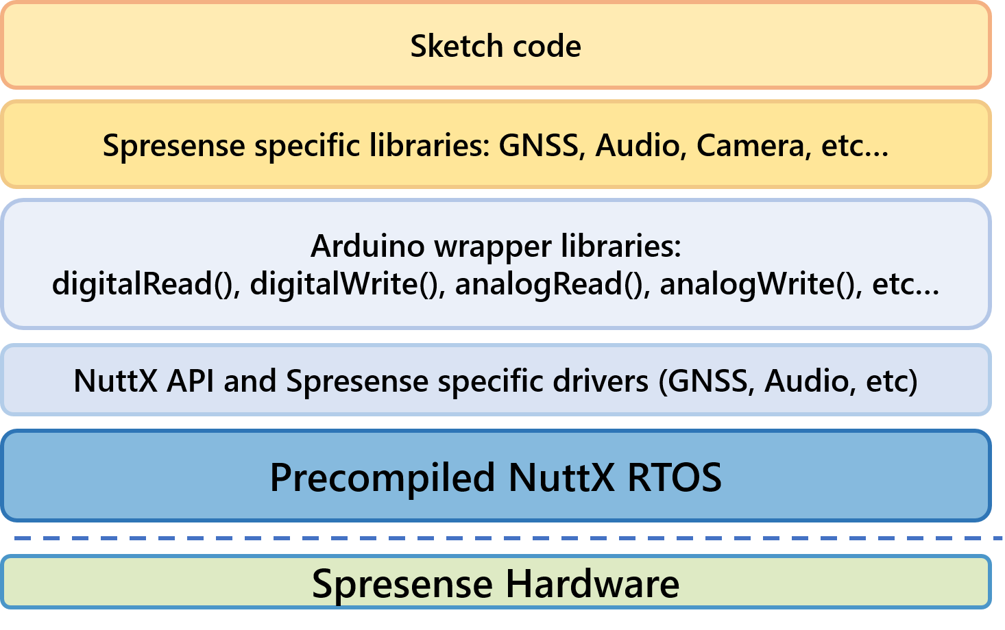
The Spresense Arduino Library is an extension wrapper library designed to make the Spresense SDK easy to use from the Arduino IDE. Internally the Arduino’s sketch works as a tasks running on the NuttX real time operating system, but when Spresense software development is undertaken using the Arduino IDE, the developer is able to program without being conscious of the Spresense SDK or the NuttX operating system.
3.1.2. Features of the Spresense Arduino Library
The Spresense Arduino Library uses the Arduino programming language and includes functions such as digitalRead and digitalWrite etc so you can use them on Spresense.
In addition it includes libraries equivalent to Arduino Libraries such as SPI and Software Serial.
|
Although the Spresense Arduino Library is largely compatible with the Arduino programming language there are some differences because of hardware features and constraints. For details, see the Functional Differences described in Spresense Arduino Library Getting Started Guide. |
The Spresense Arduino Library also offers the following libraries not found in Arduino the standard Library:
3.2. Development environment using the Spresense SDK
The Spresense SDK is a development environment that allows full access to Spresense’s unique functions. It is based on the NuttX real-time operating systems. It provides low-level APIs to maximize the performance of Spresense, such as memory optimization, power saving, and control of multi-core processing. If you are an experienced programmer and are interested in multicore programming, power saving, effective utilization of memory, please consider using the Spresense SDK.
If you would like to try developing software immediately using the Spresense SDK, please refer to following chapters.
3.2.1. Structure of the Spresense SDK
The Spresense SDK is designed to maximize access to the features of CXD5602 using NuttX as the operating system.
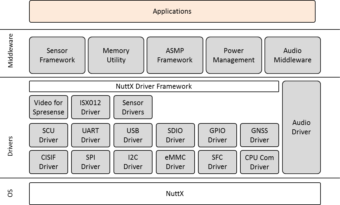
It consists of a series of drivers, implemented according to the NuttX driver framework, and middleware that provides services to software applications beyond those available from the operating system.
3.2.2. Features of the Spresense SDK
The features of the Spresense SDK are as follows.
Since it adopts NuttX as the operating system, it has the following features.
-
Multitasking RTOS
-
Optimization of configuration using Kconfig
-
Support of standard C library
-
C ++ language support
-
Support for various file systems
-
Support for various device drivers
-
Flash memory support
-
USB function (MSC and CDC) support
In addition to this, various specialist functions of CXD5602 are supported by middleware.
-
Audio recording playback function
-
Asymmetric multicore programming library
-
GPS positioning function
-
Power save function
In addition to this, almost all features of CXD5602, such as DMA controller driver, can be used within the Spresense SDK.
The usage of API is demonstrated in a range of examples.
For details, please refer to the Examples.
3.3. Development environment using CircuitPython for Spresense
CircuitPython is a programming language with added device libraries and drivers to support microcontroller hardware and sensors, and we have ported CircuitPython for Spresense.
CircuitPython is based on Python, a very popular programming language. Python is designed to be easy to read, write, and maintain. It supports modules and packages which means you can reuse your code in other projects. It has a built in interpreter which means there is no need for a compiling step to get your code to work. CircuitPython for Spresense adds support for Spresense hardware and features to this.
You might like to try CircuitPython for Spresense because:
-
There is no compiling, no downloading and no uploading needed. Create a file, edit your code, save the file, and it runs immediately.
-
Easily update your code. Since your code lives on a filesystem on Spresense, and mounts as a disk drive, you can edit it whenever you like, and in any text editor. After the initial setup, you don’t need specific drivers or software. You can also keep multiple files around for easy experimentation.
-
The serial console and REPL. These allow for live feedback from your code and interactive programming.
-
It’s Python! Python is the fastest-growing programming language. It’s taught in schools and universities. Beginners love it. CircuitPython is almost completely compatible with Python and adds hardware support.
If you would like to try developing software immediately using CircuitPython for Spresense, see CircuitPython Getting Started Guide.
4. Repository overview
Spresense is an open source project where the related source code is stored on GitHub. We highly welcome contributions from you and appreciate your help and time to make the source code better for everyone! Each repository has contribution guidelines on how you can contribute to the project. Please read them when you are ready to make your first contribution.
This chapter provides an overview of how the Spresense repositories are organized if you require to work directly with them.
For installation instructions, see the Spresense Arduino Library Getting Started Guide or Spresense SDK Getting Started Guide (CLI).
4.1. Structure
| Group | Repository name | Related repository | Description |
|---|---|---|---|
Spresense Arduino |
Repository for the Spresense Arduino Library. |
||
Example sketches applications for Spresense Arduino Library. |
|||
Spresense SDK |
Repository for the Spresense SDK. |
||
Submodule: Spresense NuttX port. |
|||
Submodule: Spresense NuttX Apps port. |
|||
HW design files |
Repository for Spresense board schematics, BOM lists etc. for you to design your own boards. |
||
4.1.1. Fetching the source
git clone https://github.com/sonydevworld/spresense-arduino-compatible.git
git clone https://github.com/sonydevworld/spresense-sketches.git
git clone --recursive https://github.com/sonydevworld/spresense.git
The URL of submodule repositories have been changed between SDK v2.x and v3.x.
If you update Spresense SDK from v2.x to v3.0.0, please run the following instructions to update the submodules.
If you still have files that have been built in an SDKv2.x environment, please do make distclean before switching versions.
cd spresense/sdk
make distclean
git fetch origin
git checkout v3.0.0
git submodule sync
git submodule update