
1. Spresense SDK Overview
This Spresense SDK is the software development kit for the CXD5602 provided by Sony Semiconductor Solutions Corp.
The image below is a block diagram of the CXD5602.
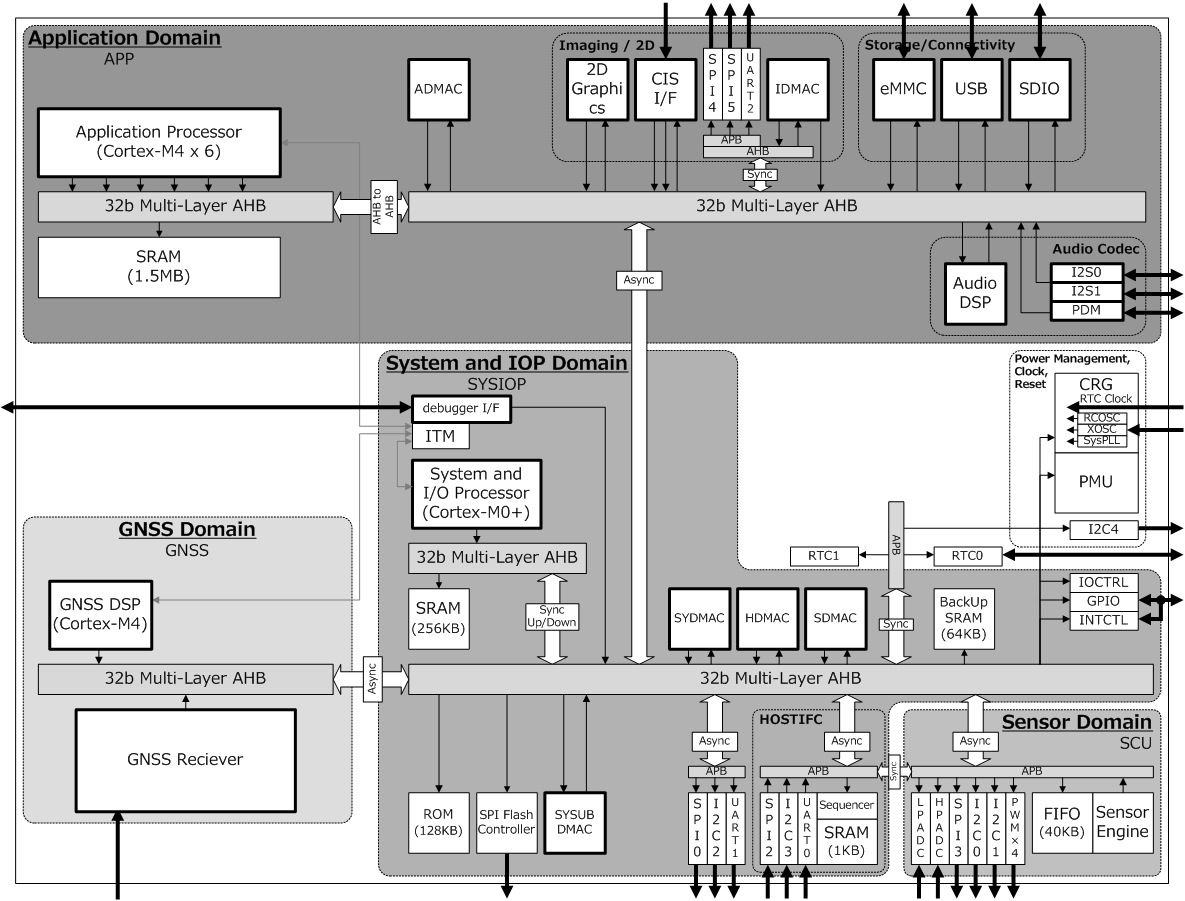
The CXD5602 comprises of four major blocks called domains.
-
Application Domain
-
This block is controlled by the user application.
-
It holds the six CPUs (Cortex®-M4F designed by ARM Co. Ltd.) where the user programs are executed.
-
-
System IOP Domain
-
This block handles the system startup and manages the power domains inside the CXD5602.
-
One ARM Cortex-M0 processor as controller for the domain.
-
-
GNSS Domain
-
This blocks handles the satellite positioning functionality.
-
One ARM Cortex-M4F is used as controller for the domain.
-
-
Sensor Domain
-
This block autonomously performs sensor data acquisition that is connected to the I2C or SPI bus, giving the chip its unique low power continuous sensing capability.
-
For further information about the CXD5602, please refer to the Sony Semiconductor Solutions Co. Spresense webpage.
Spresense SDK provides software drivers to control the hardware blocks. Spresense SDK uses NuttX as real time operating system which provides functions to utilize the unique features of the CXD5602.
The drivers in Spresense SDK are implemented using the NuttX framework which is similar to the Linux framework.
Spresense’s middleware layer provides an abstraction of Spresense specific functions like Audio, GNSS and ASMP on top of the driver layer.
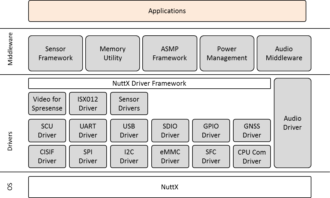
The table below presents the middleware components and drivers provided by the Spresense SDK.
| Module Name | Summary |
|---|---|
Audio Middleware |
Provides the audio functions. Record and playback in various formats. Supports various data paths. Performs audio processing. |
Sensor Framework |
Provides sensor data exchange functionality using a Publish-Subscribe architecture |
Memory Utility |
Provides a fixed-size memory pool function with a reference counter and task synchronization mechanism. |
ASMP Framework |
Manages 12 tiles of memory, a core feature of CXD5602 memory structure, to distribute the processing load of user programs across the different processor cores. |
Power Management |
Functions for power save. |
GNSS Driver |
CXD5602 has a HW subsystem that performs GNSS positioning. This driver interacts with that subsystem and provides the user with functions related to GNSS as a character device. |
Read the chapter Spresense SDK functionality for details on each module.
2. License
As with NuttX, Spresense SDK has been released as open source under the 3-Clause BSD license. Detailed license terms are as follows.
3. System boot sequence
Booting of the CXD5602 starts when reset is inactivated. The loader.espk will be loaded into RAM and executed and during this time, control of the CPU is transferred to loader.espk.
Loader.espk load nuttx.spk, this will start the application CPU.
Since nuttx.spk is a binary built with this SDK, the executed contents of nuttx.spk can vary depending on of the settings and built-in applications.
When GNSS is being used in an application, gnss.espk is loaded by loader.espk when the GNSS API is initialized.
Therefore, loader.espk and gnss.espk are essential binaries when using the Spresense board.
For information on how to obtain the binaries, please refer to here.
4. Software configuration management
This chapter gives an overview of the source code of Spresense SDK.
4.1. Repository
Spresense SDK using 2 repositories.
| Name | Submodule | Description |
|---|---|---|
Include BSP, Spresense supported driver, example application source codes. |
||
Clone repository from NuttX. And this is the kernel of Spresense. |
||
Clone repository from NuttX Apps (v2.0 or later). And this is the NuttX original application of Spresense. |
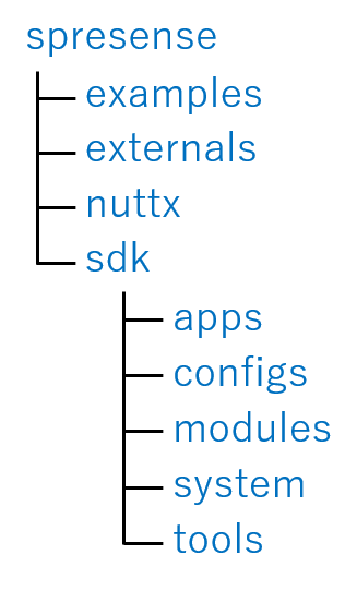
4.2. Source Tree
This is Spresense SDK directory structure.
| Name | Description |
|---|---|
spresense |
Root directory of spresense git |
examples |
Spresense SDK Example application source codes |
externals |
Spresense SDK external libraries |
nuttx |
Spresense NuttX Kernel |
sdk |
Spresense SDK supported driver, modules |
apps |
Spresense NuttX original application source codes (v2.0 or later) |
configs |
Configuration files for Spresense SDK |
modules |
Spresense SDK supported audio, sensor, etc modules |
system |
Spresense SDK system tools |
tools |
Spresense SDK build and configuration tools |
5. Spresense SDK functionality
Detailed description of the functionality provided by Spresense SDK.
5.1. BSP
5.1.1. Overview
BSP (Board Support Package) contains the source code for board specific settings and processing.
NuttX has the following driver software architecture, and the BSP directory contains the software such as Driver (Lower Half), Board specific code and Architecture specific code.
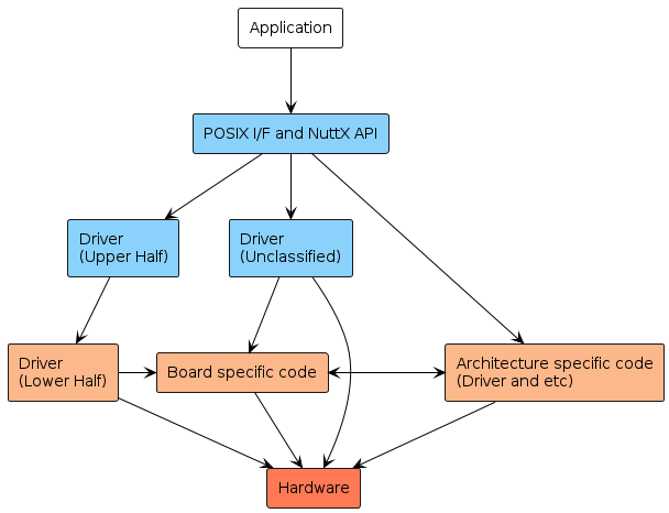
5.1.1.1. Driver (Lower Half)
NuttX has some drivers called Upper Half for standard devices and buses. The Upper Half driver provides the interfaces to the application, protocol processing, etc., the features of the Upper Half are independent of the board but it can not be used by itself. The Lower Half driver has to be implemented specifically for the board.
Spresense SDK provides Lower Half Driver for:
-
I2C (cxd56_i2c.c)
-
PWM (cxd56_pwm.c)
-
RTC (cxd56_rtc_lowerhalf.c)
-
SDIO Device (cxd56_sdhci.c)
-
Serial Device (cxd56_serial.c)
-
SPI (cxd56_spi.c)
-
Timer (cxd56_timer.c)
-
USB Device (cxd56_usbdev.c)
-
Watchdog timer (cxd56_wdt.c)
Please refer to NuttX Device Drivers for the details of NuttX’s driver.
5.1.1.2. Architecture specific code
Architecture specific drivers include drivers (such as power management) which are designed to use the specific features on the chip.
5.1.1.3. Board specific code
Board specific code is implemented depending on each board like as pin setting. These can be divided into those that can be the common and those that are completely board dependent. These are respectively located in nuttx/boards/arm/cxd56xx/common and nuttx/boards/arm/cxd56xx/<board name> (<board name> is the name of the corresponding board) .
Board Initialization Process is a part of the board specific code.
5.1.2. Directory Structure
spresense/nuttx
|-- arch
|   `-- arm
|       |-- include
|       |   `-- cxd56xx
|       `-- src
|           `-- cxd56xx
`-- boards
    `-- arm
        `-- cxd56xx
            |-- common
            |-- drivers
            `-- spresense
`-- scripts| Directory Name | Description |
|---|---|
|
There are the common code regardless of board. |
|
The Spresense board specific code like as the pin setting for Spresense board. |
|
The linker scripts. |
|
The Spresense specific drivers. |
|
The header files for calling the API provided by the chip specific device driver. |
|
The Lower Half drivers and the chip specific device drivers. |
5.1.3. Board Initialization Process
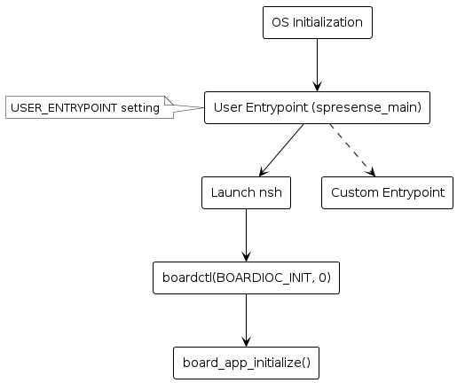
When the main CPU starts up, the NuttX kernel is initialized and the user entry point function of NuttX is called. By default, spresense_main is invoked and the function launches nsh (NuttShell). You can change the user entry point by CONFIG_USER_ENTRYPOINT configuration.
In nsh, the board initialization (boardctl()) is called. In response to this command, boardctl() will call the board-specific implementation of board_app_initialize().
Initialization the board includes the initialization of the features and the device drivers.
If you change CONFIG_USER_ENTRYPOINT from spresense_main, you need to call boardctl() from your application.
|
5.2. GPIO/Pin Specification
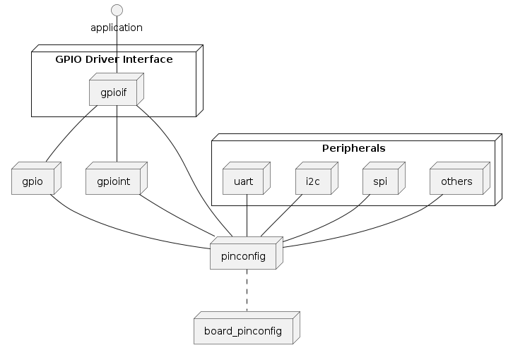
5.2.2. GPIO Driver Interface
gpioif provides the features below for use in your application.
-
GPIO pin setting
-
Function Mode
-
Input/Output enable
-
Drive Current/Slew rate
-
Pull Up/Down
-
-
GPIO interrupt setting
-
Level/Edge Trigger
-
Noise Filter
-
-
GPIO Read/Write
-
GPIO status monitor
See here for the details of API.
|
GPIO interrupts can be registered using the board_gpio_intconfig function, but the maximum number of interrupts that can be registered is fixed. Up to 12
See nuttx/arch/arm/include/cxd56xx/pin.h for pin name and pin number definitions. |
5.2.2.1. GPIO Utility tool
In system tools, GPIO Command utility is provided.
If CONFIG_SYSTEM_GPIO=y、gpio command is available from NuttShell.
Usage of gpio command
nsh> gpio
USAGE: gpio command
 stat [<from_pin>] [<end_pin>]
 conf <pin> [-m <0|1|2|3>] [-i] [-H] [-p <0|1|2|3>]
  -m: function mode
  -i: input enable
  -H: Higher drive current/slew rate
  -p: 0=float, 1=pullup, 2=pulldown, 3=buskeeper
 read <pin>
 write <pin> <0|1|-1>
If CONFIG_SYSTEM_GPIO_STATUS=y, it’s possible to display gpio status by gpio stat command.
nsh> gpio stat
-------------------------------------------------------------
( No)PIN NAME          : Mode I/O mA Pull Read IRQ Type NF EN
-------------------------------------------------------------
(  1)PIN_I2C4_BCK      : 1    I/  2  --   1    -1
(  2)PIN_I2C4_BDT      : 1    I/  2  --   1    -1
(  3)PIN_PMIC_INT      : 1    I/  2  --   0    -1
(  4)PIN_RTC_IRQ_OUT   : 0     /  2  --   0    -1
(  5)PIN_AP_CLK        : 0     /  2  --   0    -1
(  6)PIN_GNSS_1PPS_OUT : 0     /  2  --   0    -1
( 17)PIN_SPI0_CS_X     : 1     /  2  --   0    -1
( 18)PIN_SPI0_SCK      : 1    I/  2  --   1    -1
( 19)PIN_SPI0_MOSI     : 0     /  2  --   0    -1
( 20)PIN_SPI0_MISO     : 0     /  2  --   0    -1
  :
(101)PIN_MCLK          : 0     /  2  --   0    -1
(102)PIN_PDM_CLK       : 0     /  2  --   0    -1
(103)PIN_PDM_IN        : 0     /  2  --   0    -1
(104)PIN_PDM_OUT       : 0     /  2  --   0    -1
(105)PIN_USB_VBUSINT   : 1    I/  2  --   1    -1
5.2.3. Pin specification
Pins are organized into groups. Each group of pins has a set of functions, that vary depending on the mode you set. The mode can range from 0 to 3.
For example, for the PIN_PWM2,3 pins:
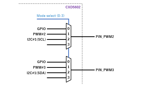
-
If you select
Mode0, the PIN_PWM2 and PIN_PWM3 pins both function as GPIO pins. -
If you select
Mode1, the PIN_PWM2 and PIN_PWM3 pins both function as PWM pins. -
If you select
Mode2, the PIN_PWM2 and PIN_PWM3 pins both function as I2C pins.
| You cannot change the function of one pin in a group without changing the others. For example, you cannot make the PIN_PWM2 pin function as a GPIO without also changing PIN_PWM3 to PWM. |
For all pins, the initial mode after a CPU reset is Mode0(GPIO).
5.2.3.1. Pin List
-
Pin Name is defined as
PIN_XXXin nuttx/arch/arm/include/cxd56xx/pin.h. -
WLCSP is the 100-pin package. Some pins are removed.
-
FCBGA is the 185-pin fully featured package.
-
ModeX describes the pin role for Modes 0-3.
| Pin Name | Arduino compatible Pin Name |
WLCSP | FCBGA | Mode0 | Mode1 | Mode2 | Mode3 | |
|---|---|---|---|---|---|---|---|---|
I2C4_BCK |
- |
* |
* |
GPIO |
I2C#4 |
|||
I2C4_BDT |
- |
* |
* |
|||||
PMIC_INT |
- |
* |
* |
GPIO |
PMIC |
PMIC Interrupt |
||
RTC_IRQ_OUT |
D41 |
* |
GPIO |
RTC_IRQ_OUT |
RTC_IRQ_OUT |
|||
AP_CLK |
D40 |
* |
* |
GPIO |
AP_CLK |
PMU_WDT |
PMU_WDT |
|
GNSS_1PPS_OUT |
D44 |
* |
GPIO |
GNSS_1PPS_OUT |
CPU_WDT |
CPU_WDT |
||
SPI0_CS_X |
- |
* |
* |
GPIO |
UART#1 |
SPI#0 |
||
SPI0_SCK |
- |
* |
* |
|||||
SPI0_MOSI |
- |
* |
GPIO |
I2C#2 |
||||
SPI0_MISO |
- |
* |
||||||
SPI1_CS_X |
- |
* |
* |
GPIO |
SPI#1 |
SPI#0 |
||
SPI1_SCK |
- |
* |
* |
|||||
SPI1_IO0 |
- |
* |
* |
|||||
SPI1_IO1 |
- |
* |
* |
|||||
SPI1_IO2 |
- |
* |
* |
GPIO |
||||
SPI1_IO3 |
- |
* |
* |
|||||
SPI2_CS_X |
D42 |
* |
* |
GPIO |
SPI#2 |
UART#0 |
I2C#3 |
|
SPI2_SCK |
D43 |
* |
* |
|||||
SPI2_MOSI |
D04 |
* |
* |
GPIO |
||||
SPI2_MISO |
D08 |
* |
* |
|||||
HIF_IRQ_OUT |
D02 |
* |
* |
GPIO |
HIF_IRQ_OUT |
HIF_IRQ_OUT |
GNSS_1PPS_OUT |
|
HIF_GPIO0 |
D39 |
* |
GPIO |
GPS_EXTLD |
||||
SEN_IRQ_IN |
D22 |
* |
* |
GPIO |
SEN_IRQ_IN |
|||
SPI3_CS0_X |
D32 |
* |
* |
GPIO |
SPI3_CS0_X |
|||
SPI3_CS1_X |
D07 |
* |
* |
GPIO |
SPI3_CS1_X |
|||
SPI3_CS2_X |
- |
* |
* |
GPIO |
SPI3_CS2_X |
|||
SPI3_SCK |
D29 |
* |
* |
GPIO |
SPI#3 |
|||
SPI3_MOSI |
D31 |
* |
* |
|||||
SPI3_MISO |
D30 |
* |
* |
|||||
I2C0_BCK |
D15 |
* |
* |
GPIO |
I2C#0 |
|||
I2C0_BDT |
D14 |
* |
* |
|||||
PWM0 |
D06 |
* |
* |
GPIO |
PWM#0,1 |
|||
PWM1 |
D05 |
* |
* |
|||||
PWM2 |
D09 |
* |
* |
GPIO |
PWM#2,3 |
I2C#1 |
||
PWM3 |
D03 |
* |
* |
|||||
IS_CLK |
- |
* |
GPIO |
CMOS Image Sensor |
||||
IS_VSYNC |
- |
* |
||||||
IS_HSYNC |
- |
* |
||||||
IS_DATA0 |
- |
* |
||||||
IS_DATA1 |
- |
* |
||||||
IS_DATA2 |
- |
* |
||||||
IS_DATA3 |
- |
* |
||||||
IS_DATA4 |
- |
* |
||||||
IS_DATA5 |
- |
* |
||||||
IS_DATA6 |
- |
* |
||||||
IS_DATA7 |
- |
* |
||||||
UART2_TXD |
D01 |
* |
* |
GPIO |
UART#2 |
|||
UART2_RXD |
D00 |
* |
* |
|||||
UART2_CTS |
D27 |
* |
* |
|||||
UART2_RTS |
D28 |
* |
* |
|||||
SPI4_CS_X |
D10 |
* |
* |
GPIO |
SPI#4 |
|||
SPI4_SCK |
D13 |
* |
* |
|||||
SPI4_MOSI |
D11 |
* |
* |
|||||
SPI4_MISO |
D12 |
* |
* |
|||||
EMMC_CLK |
D23 |
* |
* |
GPIO |
eMMC |
SPI#5 |
||
EMMC_CMD |
D24 |
* |
* |
|||||
EMMC_DATA0 |
D16 |
* |
* |
|||||
EMMC_DATA1 |
D17 |
* |
* |
|||||
EMMC_DATA2 |
D20 |
* |
* |
GPIO |
||||
EMMC_DATA3 |
D21 |
* |
* |
|||||
SDIO_CLK |
- |
* |
GPIO |
SDIO |
SPI#5 |
|||
SDIO_CMD |
- |
* |
||||||
SDIO_DATA0 |
- |
* |
||||||
SDIO_DATA1 |
- |
* |
||||||
SDIO_DATA2 |
- |
* |
GPIO |
|||||
SDIO_DATA3 |
- |
* |
||||||
SDIO_CD |
D36 |
* |
GPIO |
SDIO |
||||
SDIO_WP |
D37 |
* |
||||||
SDIO_CMDDIR |
D33 |
* |
GPIO |
SDIO |
||||
SDIO_DIR0 |
D34 |
* |
||||||
SDIO_DIR1_3 |
D35 |
* |
||||||
SDIO_CLKI |
D38 |
* |
GPIO |
SDIO |
||||
I2S0_BCK |
D26 |
* |
* |
GPIO |
I2S#0 |
|||
I2S0_LRCK |
D25 |
* |
* |
|||||
I2S0_DATA_IN |
D19 |
* |
* |
|||||
I2S0_DATA_OUT |
D18 |
* |
* |
|||||
I2S1_BCK |
LED0 |
* |
GPIO |
I2S#1 |
||||
I2S1_LRCK |
LED1 |
* |
||||||
I2S1_DATA_IN |
LED2 |
* |
||||||
I2S1_DATA_OUT |
LED3 |
* |
||||||
MCLK |
- |
* |
* |
GPIO |
MCLK |
|||
PDM_CLK |
- |
* |
* |
GPIO |
PDM |
|||
PDM_IN |
- |
* |
* |
|||||
PDM_OUT |
- |
* |
* |
|||||
USB_VBUSINT |
- |
* |
* |
GPIO |
USB VBUS Interrupt |
5.2.3.2. Pin Configuration
Pin mode configuration is implemented in device the drivers. For example, the pin mode setting is performed in I2C or SPI driver, the correct pin mode is selected for the I2C or SPI function as appropriate. Therefore, there is no need for the user application to change pin mode directly.
Only when pins are used as Mode0(GPIO) is it appropriate to use APIs defined in gpioif.
5.2.3.2.1. Board Specific Pin Pull and Drive Current Setting
Pin pull up and down settings and drive current setting are defined in nuttx/arch/arm/src/cxd56xx/hardware/cxd5602_pinconfig.h
The setting is Hi-Z floating by default, and drive current of the most pins is set to 2mA.
If you would like to change these default setting you do not need to modify cxd5602_pinconfig.h directly. You can select the following configuration CONFIG_BOARD_CUSTOM_PINCONFIG=y
and update
nuttx/boards/arm/cxd56xx/spresense/include/board_pinconfig.h.
In case of Spresense board,
/* Customize from default to the board specific pin configuration
 * The default pin configurations are defined in
 * boards/arm/cxd56xx/spresense/include/board_pinconfig.h.
 *
 *  Mode: shared pin function mode
 *  ENZI: 1=Input Enable, 0=Input Disable
 *  4mA : Drive Current 1=4mA, 0=2mA
 *  Pull: 0=HiZ floating, PINCONF_PULLUP, PINCONF_PULLDOWN
 *                                                                      M  E     P
 *                                                  P                   o  N  4  u
 *                                                  i                   d  Z  m  l
 *                                                  n                   e  I  A  l
 */

#undef PINCONF_UART2_CTS
#define PINCONF_UART2_CTS                   PINCONF(PIN_UART2_CTS,      1, 1, 0, PINCONF_PULLDOWN)

#undef PINCONF_SPI4_CS_X
#undef PINCONF_SPI4_SCK
#undef PINCONF_SPI4_MOSI
#define PINCONF_SPI4_CS_X                   PINCONF(PIN_SPI4_CS_X,      1, 0, 1, 0)
#define PINCONF_SPI4_SCK                    PINCONF(PIN_SPI4_SCK,       1, 0, 1, 0)
#define PINCONF_SPI4_MOSI                   PINCONF(PIN_SPI4_MOSI,      1, 0, 1, 0)

#undef PINCONF_PWM0
#undef PINCONF_PWM1
#undef PINCONF_PWM2
#undef PINCONF_PWM3
#define PINCONF_PWM0                        PINCONF(PIN_PWM0,           1, 0, 1, 0)
#define PINCONF_PWM1                        PINCONF(PIN_PWM1,           1, 0, 1, 0)
#define PINCONF_PWM2                        PINCONF(PIN_PWM2,           1, 0, 1, 0)
#define PINCONF_PWM3 PINCONF(PIN_PWM3, 1, 0, 1, 0)-
Pull down of UART2_CTS
-
Change the drive current of SPI4 from 2mA to 4mA
-
Change the drive current of PWM from 2mA to 4mA
5.3. Audio Subsystem
5.3.1. General
The CXD5602 SoC has an Audio Subsystem to support audio. It has the following functions:
-
Audio Codec hardware (AD/DA, DNC, DEQ, etc.) control
-
Audio Player function
-
Audio Recorder function
-
Bluetooth-related function (for BT-A2DP)
-
Filter functions (eg bandpass filter for voice calls etc.)
This document describes software to control the audio functions that can be implemented on the CXD5602 hardware. Please refer to Spresense Hardware Documents for Audio Hardware.
| The current Firmware does not support Bluetooth functions (for BT-A2DP) and Sound Effector functions (eg band pass filters for voice calls etc) |
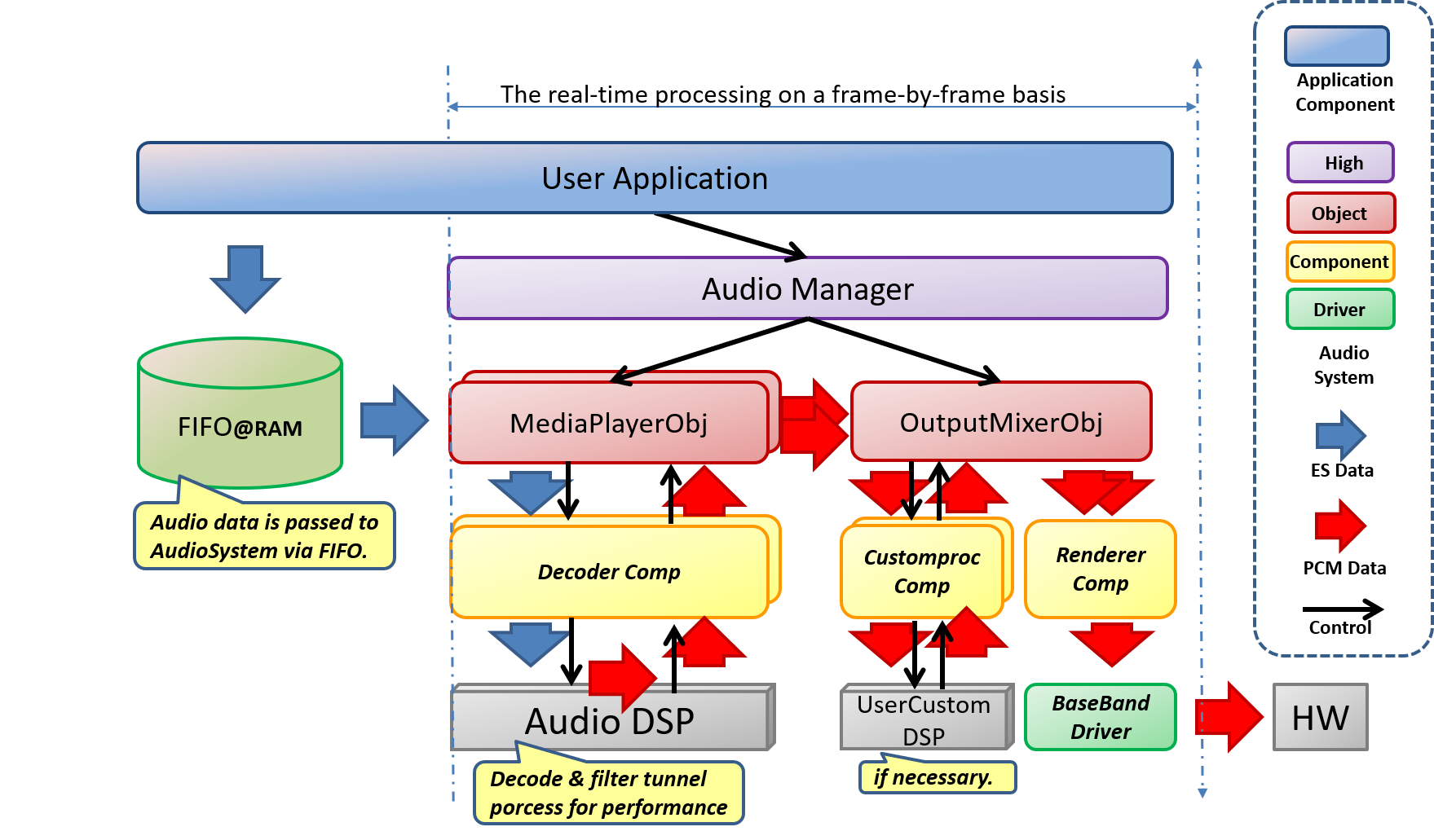
5.3.2. About layer structure
The stack diagram of the audio subsystem is shown below.
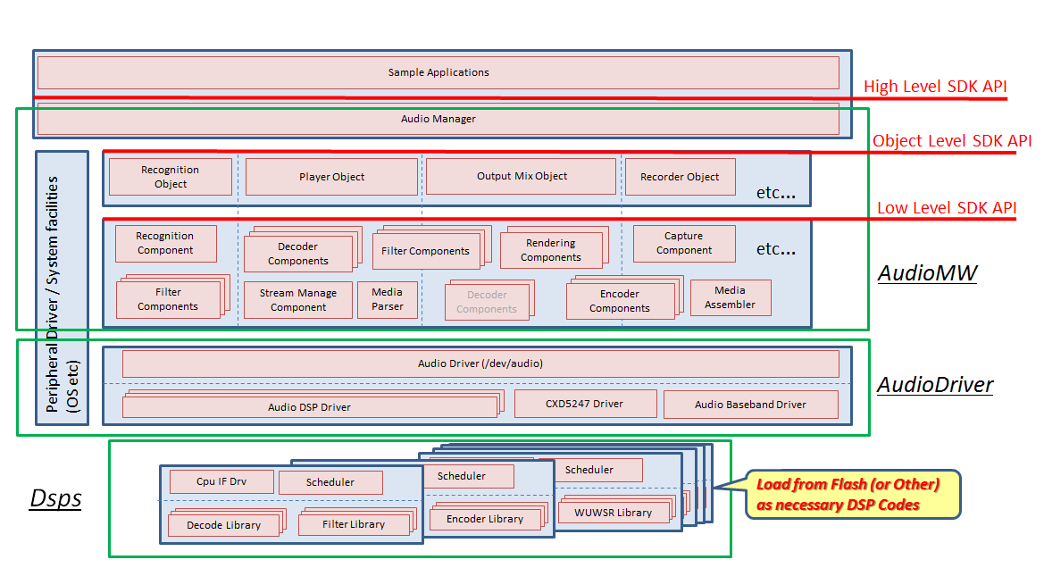
The audio subsystem has three major layers:
- Audio Manager (High Level API)
-
The Audio Manager is the highest layer and controls at the highest level of abstraction. It coordinates the whole system.
- Object Layer (ObjectLevel API)
-
The Object Layer provides simpler functions to control the audio system. You can create more flexible applications by using the Component Layer API.
- Component Layer (Low Level API)
-
The Component Layer controls the audio system at the lower level of abstraction. Audio processing, with high degree of flexibility, can be achieve by configuring processing with a combination of Component Layer processing blocks.
5.3.3. High Level API
You can use the high-level Audio Utility Libraries to control the Audio Manager. The following is a stack diagram of the Audio Subsystem:
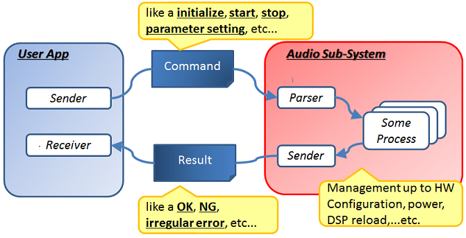
5.3.3.1. Control System by Command send and receive
You can control the Audio Subsystem using the high-level API Command System. To send a command to the Audio Subsystem, use AS_SendAudioCommand ; the command format is AudioCommand . To receive results from the Audio Subsystem, call AS_ReceiveAudioResult . The result format is AudioResult .
The command is a synchronous command. After issuing the command, the next command can not be issued until the result is returned. When using the High Level API via Audio Manager , please program so that send / receive procedures are paired with one command unit.
|
5.3.3.1.1. About control data format (command format)
The command object is 1 word (4 bytes) AudioCommandHeader
It is a data structure that starts with, and then adds as many parameter areas as necessary.
Because the command object is based on a word unit, it consists of integral multiple of 1 word (32 bits, 4 bytes).
Set 0 in the reserved field of the command object.
typedef struct
{
  AudioCommandHeader header;
  union
  {
    Command Parameters (Payload)
    ...
    ...
  };
} AudioCommand;The first one word (4 bytes) of all command objects has the following format. This one word is called the command header (AudioCommandHeader).
typedef struct
{
  uint8_t reserved;
  uint8_t sub_code;
  uint8_t command_code;
  uint8_t packet_length;
} AudioCommandHeader;- packet_length
-
Indicates the length of the command object including the command header. All command objects are composed of an integer number of words (4 bytes), and the value specified by packet_length is one quarter of the word length of the command packet, that is, the byte length of the command object.
- command_code
-
Code specific to the command. The value 0x00 is not used. See Command list for the list of commands.
- sub_code
-
This is a code to identify the target to be set and controlled in each command.
5.3.3.1.2. Notification data format (result format)
The result object is a data structure starting with 1 word (4 bytes) AudioResultHeader followed by as many parameter areas as necessary.
Since the result object is based on a word unit, it consists of an integral multiple of 1 word (32 bits, 4 bytes).
Ignore the reserved field of the result object.
The first 1 word (4 bytes) of all result objects has the following format. This one word is called the result header (AudioResultHeader).
typedef struct
{
  AudioResultHeader header;
  union
  {
    Result Parameters (Payload)
    ...
    ...
  };
} AudioResult;The first one word (4 bytes) of all result objects has the following format. This one word is called the result header (AudioCommandHeader).
typedef struct
{
  uint8_t reserved;
  uint8_t sub_code;
  uint8_t result_code;
  uint8_t packet_length;
} AudioResultHeader;- packet_length
-
Indicates the length of the result object including the result header. All result objects consist of an integer number of words (4 bytes), and the value specified by packet_length is the word length of the result object, that is, 1/4 of the byte length of the result object.
- result_code
-
It is a code to identify the result type. See Result list for the list of results.
- sub_code
-
The same value as the sub_code of the executed command is entered.
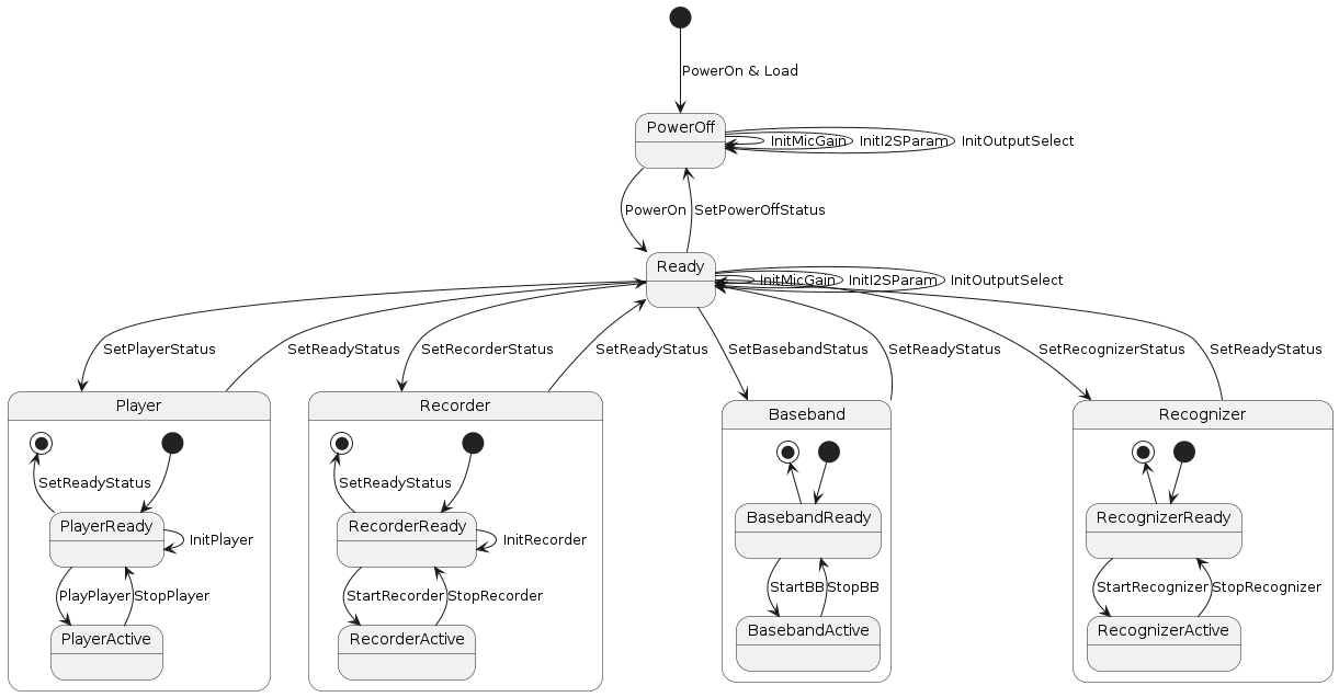
5.3.3.2. State Transition
The High Level API has several states. The state transition diagram is shown below.
The explanation of each mode is as follow.
-
PowerOff state
It is the state immediately after the object of the audio subsystem is generated and started up. If you do not use audio, transition to this state will make the power consumption in the audio block almost 0.
Transition only to the Ready state by the AUDCMD_POWERON command.
-
Ready state
I am preparing to turn on the audio block and operate the audio function in the operation mode. In this state, the power consumption has not decreased, but since the IO / analog is running, it is possible to perform mode transition promptly.
The state transition is as follow.
The AUDCMD_SETPOWEROFFSTATUS command allows you to enter the PowerOff state.
The AUDCMD_SETPLAYERSTATUS command allows you to enter the Player state.
The AUDCMD_SETRECORDERSTATUS command allows you to enter the Recorder state.
The AUDCMD_SETBASEBANDSTATUS command allows you to enter the Baseband state.
The AUDCMD_SETRECOGNIZERSTATUS command allows you to enter the Recognizer state.
-
Player state
It is a state to realize the function to decode the compressed audio file from storage such as SD card and the network such as WiFi / LTE, and to sound to AnalogOut and I2S. It has two substates in the state: PlayerReady state and PlayerActive state.
The PlayerReady state is the state of music playback stop. AUDCMD_PLAYPLAYER Transit to PlayerActive and perform music playback operation.
The PlayerActive state is the state during music playback. AUDCMD_STOPPLAYER Transit to PlayerReady and stop music playback.
AUDCMD_SETREADYSTATUS Transition to the Ready state.
-
Recorder status
It is a state that compresses the voice data input from Mic, realizes the function of exporting to the storage such as SD card, and sending it to a communication network such as WiFi / LTE.
Within the state it has two substates, the RecorderReady state and the RecorderActive state.
The RecorderReady state is the state of audio recording stop. AUDCMD_STARTREC Transitions to RecorderActive and performs voice recording operation.
The RecorderActive state is the state during voice recording. AUDCMD_STOPREC Transit to RecorderReady and stop recording voice.
AUDCMD_SETREADYSTATUS Transition to the Ready state.
-
Baseband state
It is a state that realizes the function of internally processing the sound data input from Mic, and outputting it to AnalogOut or I2S. Within the state it has two substates, the BasebandReady state and the BasebandActive state.
The BasebandReady state is the state of audio input / output stop. AUDCMD_STARTBB Transit to BasebandActive and start voice input / output operation.
The RecorderActive state is a state during audio input / output operation. AUDCMD_STOPBB Transit to BasebandReady and stop audio input / output operation. AUDCMD_SETREADYSTATUS Transition to the Ready state.
| The current Firmware does not support BaseBand State. |
-
Recognizer state
It is a state that realizes the function of performing recognition processing from the voice data input from Mic. It has two sub-states, Recognizer Ready state and Recognizer Active state. The Recognizer Ready state is the state in which the voice input/output for recognition is stopped. Transition to RecognizerActive by AUDCMD_START_RECOGNIZER and start voice input/output operation. The RecognizerActive state is the voice input/output enable. The voice input/output operation is stopped by AUDCMD_STOP_RECOGNIZER and transition to Recognizer Ready.
5.3.3.3. Command list
The lists of each command are as follows. You can request each function for the audio subsystem by specifying each command ID into the Command header.
5.3.3.3.1. General or common Command
Common commands in any state. You can call it from any state.
| Command Name | Command ID | Response Result | Description |
|---|---|---|---|
0x01 |
NotifyStatus |
Get the current state |
For details, refer to the Doxygen file below.
5.3.3.3.2. Baseband Initialize Command
Command to initialize Baseband HW. You can only call from the Ready state.
| Command Name | Command ID | Response Result | Description |
|---|---|---|---|
0x53 |
InitMicGainCmplt |
Set the microphone gain |
|
0x54 |
InitI2SCmplt |
Configure I2S |
|
0x56 |
InitOutputSelectCmplt |
Configure the device to be sounded |
|
0x58 |
InitClearStereoCmplt |
Set the clear stereo function |
|
0x5c |
SetRenderingClkCmplt |
Switch HiResolution setting |
|
0x5d |
SetSpDrvCmplt |
Set the drive capacity of the speaker |
For details, refer to the Doxygen file below.
5.3.3.3.3. Baseband Set Command
This command is for setting Baseband HW. It can be called from a state other than the PowerOff state.
| Command Name | Command ID | Response Result | Description |
|---|---|---|---|
0x59 |
SetVolumeCmplt |
Perform volume setting for pronunciation |
|
0x5a |
SetVolumeMuteCmplt |
Set mute of sound volume |
|
0x5b |
SetBeepCmplt |
BEEP Set the sound |
|
0x5e |
SetMicMapCmplt |
Select the microphone and set the order |
For details, refer to the Doxygen file below.
5.3.3.3.4. Player Command
This command controls player. You can call it from Player state.
| Command Name | Command ID | Response Result | Description |
|---|---|---|---|
0x21 |
InitPlayCmplt |
Sets the playback information of the player |
|
0x22 |
PlayCmplt |
Decodes from the beginning of the buffer |
|
0x23 |
StopPlayCmplt |
Stops Player regardless of buffer state |
|
0x24 |
ClkRecoveryComplete |
Fine adjustment of the sound output time |
|
0x25 |
SetDecoderGainComplete |
Multiply the sound output level by Gain for L / R respectively |
For details, refer to the Doxygen file below.
5.3.3.3.5. Recorder Command
This command controls the Recorder. You can call it from Recorder state.
| Command Name | Command ID | Response Result | Description |
|---|---|---|---|
0x31 |
InitRecCmplt |
Initializes the voice recording function |
|
0x32 |
RecCmplt |
Start audio recording |
|
0x33 |
StopRecCmplt |
Stop audio recording |
For details, refer to the Doxygen file below.
5.3.3.3.6. State Transition Command
| Command Name | Command ID | Response Result | Description |
|---|---|---|---|
0x71 |
StatusChanged |
Transit to Ready state |
|
0x72 |
StatusChanged |
Transits to Power Off state |
|
0x73 |
StatusChanged |
Transit to Baseband state |
|
0x75 |
StatusChanged |
Transit to Player state |
|
0x76 |
StatusChanged |
Transitions to Recorder state |
|
0x77 |
StatusChanged |
Transit to Ready state |
|
0x78 |
StatusChanged |
Audio path Transit to the through state |
|
0x79 |
StatusChanged |
Transitions to Recognizer state |
For details, refer to the Doxygen file below.
5.3.3.4. Result list
There are the lists of result from the audio subsystem. You will be notified the result ID that stored in the Result header.
5.3.3.4.1. General or Common Result
| Result Name | Command ID | Trigger Command | Description |
|---|---|---|---|
0x01 |
GetStatus |
Notify the current state |
5.3.3.4.2. Baseband Initialize Result
| Result Name | Command ID | Trigger Command | Description |
|---|---|---|---|
0x53 |
InitMicGain |
Notify completion of the microphone gain setting |
|
0x54 |
InitI2SParam |
Notify completion of the I2S setting |
|
0x56 |
InitOutputSelect |
Notify completion of the device setting to be sounded |
|
0x58 |
InitClearStereo |
Notify completion of the clear stereo setting |
|
0x5c |
InitRenderClk |
Notify completion to be switched to the Hi-Resolution setting |
|
0x5d |
SetSpDrv |
Notify completion of setting to drive capability of speaker |
5.3.3.4.3. Baseband Set Result
| Result Name | Command ID | Trigger Command | Description |
|---|---|---|---|
0x59 |
SetVolume |
Notify completion of the volume settings for pronunciation |
|
0x5a |
SetVolumeMute |
Notify completion of the mute setting of the sound volume |
|
0x5b |
SetBeep |
Notify completion of the beep sound setting |
|
0x5e |
SetMicMap |
Notify completion of selecting mic and setting channel order |
5.3.3.4.4. Player Result
| Result Name | Command ID | Trigger Command | Description |
|---|---|---|---|
0x21 |
InitPlayer |
Notify completion of the playback setting |
|
0x22 |
StartPlayer |
Notify the playback to be beginned |
|
0x23 |
StopPlayer |
Notify the playback to be stopped |
|
0x24 |
ClkRecovery |
Notify completion of the fine adjustment of the sound output time |
|
0x25 |
SetDecoderGain |
Notify completion of the L / R gain controls |
5.3.3.4.5. Recorder Result
| Result Name | Command ID | Trigger Command | Description |
|---|---|---|---|
0x31 |
nitRecorder |
Notify completion to be initialized the voice recording |
|
0x32 |
StartRecorder |
Notify the recorder to begin |
|
0x33 |
StopRecorder |
Notify the recorder to be stopped |
5.3.3.4.6. State Transition Result
| Result Name | Command ID | Trigger Command | Description |
|---|---|---|---|
0x71 |
PowerOn SetPowerOffStatus SetBaseBandStatus SetPlayerStatus SetRecorderStatus SetRecognizerStatus SetReadyStartus |
Notify completion of the state transition |
5.3.3.5. Details of the command packets
5.3.3.5.11. SetMicMap
| Refer to MIC channel select map settings for MicMap settings. |
5.3.3.7. Memory management and inter-task synchronization
5.3.3.7.1. Memory Manager Library
AudioSubSystem manages the data area to be used with a special management method. A library called MemoryManager in MemoryUtility secures the required memory area as a fixed-size memory pool according to the layout information of the memory_layout file. You can have multiple Layout information in one file, and you can secure the necessary memory for each function by specifying the Layout number.
This memory layout is to be freely decided according to the needs of Application, but please note that the minimum necessary resources are available for each function.
For details, refer to the library description of Memory Manager.
Also, please refer to the explanation of each example for necessary Layout according to each function.
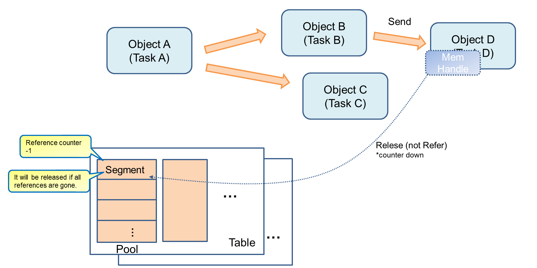
Each object in AudioSubSystem creates an instance of MemHandle that points to a segment of the required memory area, thereby securing a memory segment linked to it and using it.
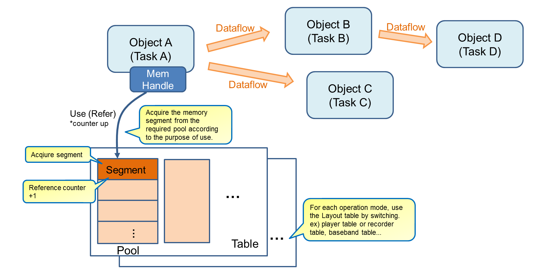
By passing an instance of this MemHandle to the object located next to the data pipeline, the next object can be used by the next object, and if it becomes unnecessary, by destroying this instance , The memory area is freed.
Instances can be copied, secured instances are secured while necessary objects are required for their own memory, and even if they are no longer needed, they can be secured / released securely even if they are discarded at their own timing.
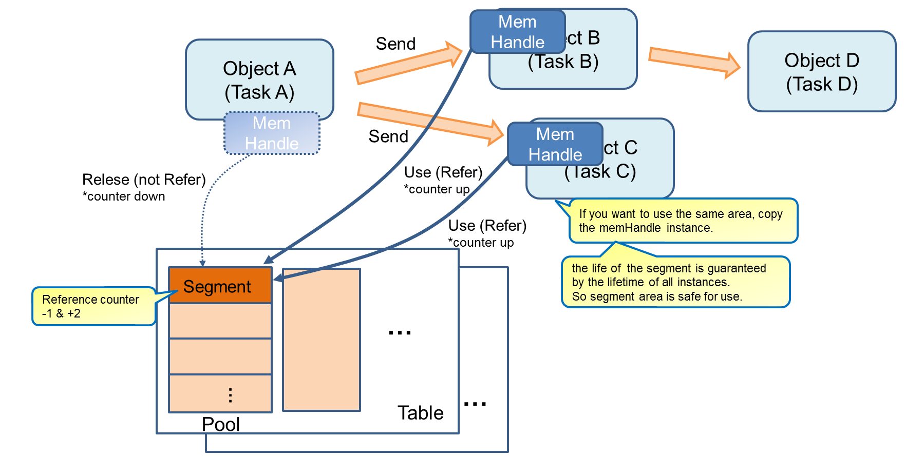
When the use of a segment becomes unnecessary, an object executed asynchronously is implicitly referenced by destroying the instance without being conscious of memory management.
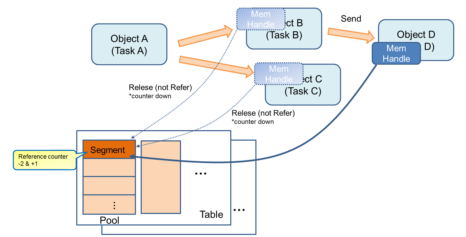
This makes it easy to manage memory between asynchronous objects. When all references are gone, release the memory.
For Memory Layout, you need to prepare a header file group to use Memory Layout in advance. These header files are created by creating a Memory Layout definition file (mem_layout.conf) and using the tool.
- Usage
python3 mem_layout.conf [layout_header] [fence_header] [pool_header]
The explanation of each argument is as follow.
| mem_layout.conf |
Memory Layout definition file |
| layout_header |
Header file in which various constant values are output as macros. A "mem_layout.h" is generated without this argument. |
| fence_header |
Header file to output FixedArea’s memory fence address. A "fixed_fence.h" is generated without this argument. It is a file used by "Memory Manager" and should not be used by users. |
| pool_header |
Header file to which various definitions of PoolArea are output. A "pool_layout.h" is generated without this argument. It is a file used by "Memory Manager", so please do not use it by users. |
5.3.3.7.2. Message Library
In order to use this memory management mechanism, it is necessary to send and receive class objects between tasks. In order to realize this, we have prepared a message library that allows sending and receiving class instances to the task synchronization mechanism, which AudioSubSystem uses.
By adding the ID of the sending / receiving destination to the object in each task, it is possible to send to the task you want to send and receive.
For example, in the case of sending, the object is sent to the ID of the destination, and the task of the receiving side will be received only when a transmission request of your ID occurs. Until reception, the task sleeps and waits.
By doing this, AudioSubSystem is doing object design by event driven.
For Message, it is necessary to prepare a header file group for using Message in advance. These header files are created by creating a MessageQueueLayout definition file (msgq_layout.conf) and using the tool.
- Usage
python3 msgq_layout.conf [start_address] [size] [id_header] [pool_header]
The explanation of each argument is as follow.
| msgq_layout.conf |
Message Layout definition file |
| start_address |
Address of message area. If this argument is nothing, then start_addr is set from "mem_layout.h". |
| size |
Area size in bytes. If this argument is nothing, then size is set from "mem_layout.h". |
| id_header |
File to which message queue ID macro is output. A "msgq_id.h" is generated without this argument. |
| pool_header |
File in which definition of message queue pool is output. A "msgq_pool.h" is generated without this argument. |
For details, refer to the explanation of the Message Library.
5.3.3.7.3. Simple FIFO Library
When audio data is exchanged between AudioSubSystem and user application FIFO is used. This FIFO is a simple FIFO and there is nothing special to mention.
For details, refer to the library description of Simple FIFO.
5.3.3.9. Audio Player
The Audio Subsystem has an audio player function with sound effects.
The following is a simple data flow diagram of the audio player:
When Audio SubSystem operates with PlayerMode, user Application inputs ES data into FIFO. When Player is started with a certain level of accumulation, this ES data will be consumed in accordance with the playing time. Unless this FIFO underflow, audio data will play without interruption.
You can generate two instance of MediaPlayer. The decoded audio which is output from both players will be mixed by OutputMixer, and it will be sounded out simultaneously.
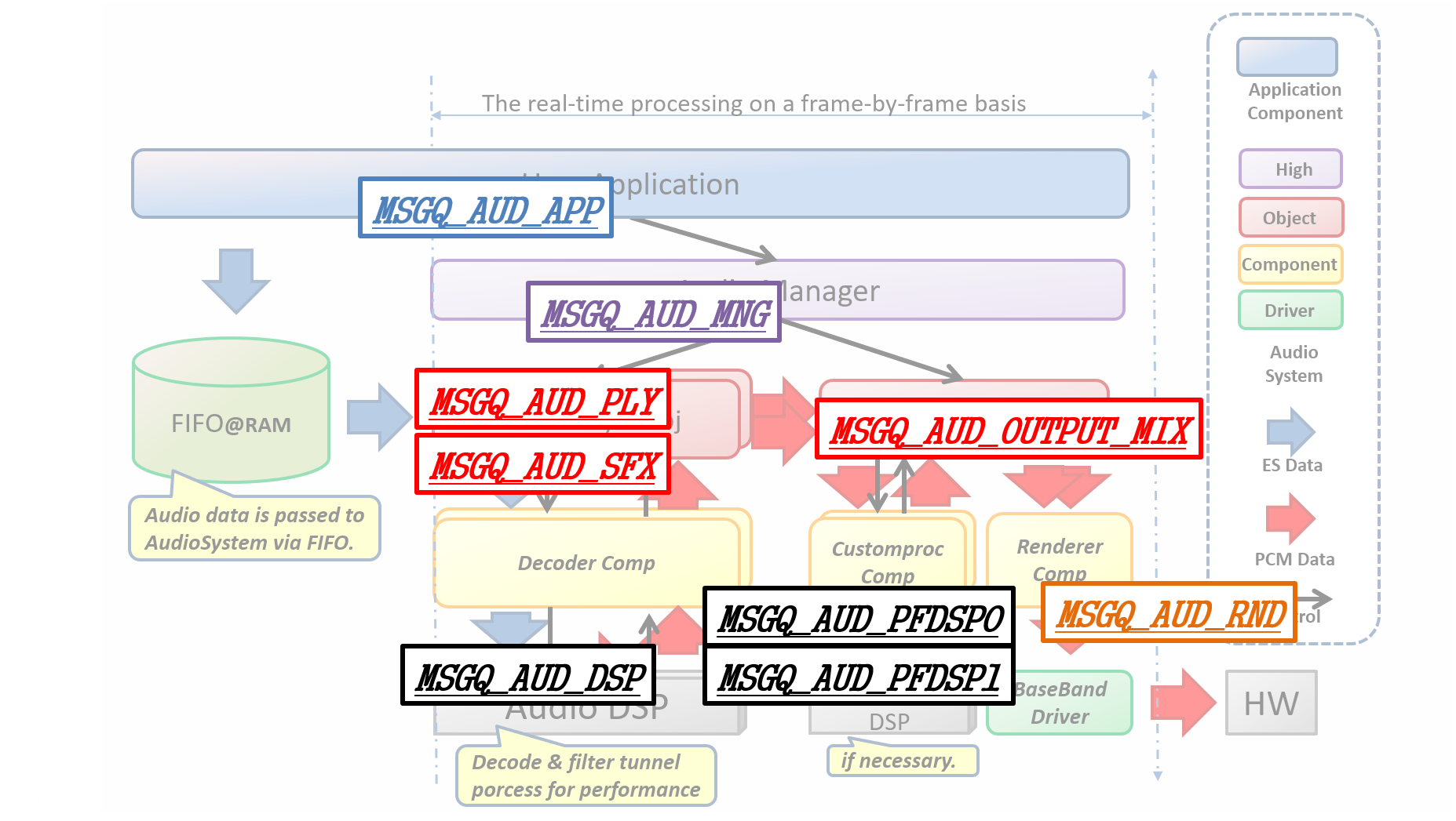
The data flow communicates via message sending internally. Message communication has an ID for each client. In the case of Audio Player, the ID will be as follow for the Layout example:
User Application                        : MSGQ_AUD_APP
Audio Manager                           : MSGQ_AUD_MNG
Audio Player0                           : MSGQ_AUD_PLY0
Audio Player1                           : MSGQ_AUD_PLY1           # Set this value when you use player1, in other case, set 0xff.
Output Mixer                            : MSGQ_AUD_OUTPUT_MIX
Audio DSP                               : MSGQ_AUD_DSP
Rendering Component(Audio Player0)      : MSGQ_AUD_RND_PLY0
Rendering Component(Audio Player1)      : MSGQ_AUD_RND_PLY1       # Set this value when you use player1, in other case, set 0xff.
Rendering Component Sync(Audio Player0) : MSGQ_AUD_RND_PLY0_SYNC
Rendering Component Sync(Audio Player1) : MSGQ_AUD_RND_PLY1_SYNC  # Set this value when you use player1, in other case, set 0xff.
Post Filter (Channel0)                  : MSGQ_AUD_PFDSP0
Post Filter (Channel1) : MSGQ_AUD_PFDSP1| MSGQ_AUD_RND_PLY0 / PLY1_SYNC will be deleted. |
In addition, the data area of each data is as follows.
ES Data (Audio Player0)                           : S0_DEC_ES_MAIN_BUF_POOL
ES Data (Audio Player1)                           : S0_DEC_ES_SUB_BUF_POOL    # Set this value when you use player1, in other case, set S0_NULL_POOL.
PCM Data (Audio Player0)                          : S0_REND_PCM_BUF_POOL
PCM Data (Audio Player1)                          : S0_REND_PCM_SUB_BUF_POOL  # Set this value when you use player1, in other case, set S0_NULL_POOL.
Audio Decoder DSP Command                         : S0_DEC_APU_CMD_POOL
SamplingRateConverter Work Buffer (Audio Player0) : S0_SRC_WORK_BUF_POOL
SamplingRateConverter Work Buffer (Audio Player1) : S0_SRC_WORK_SUB_BUF_POOL  # Set this value when you use player1, in other case, set S0_NULL_POOL.
Post Filter PCM Data (Channel0)                   : S0_PF0_PCM_BUF_POOL
Post Filter PCM Data (Channel1)                   : S0_PF1_PCM_BUF_POOL
Post Filter DSP Command (Channel0)                : S0_PF0_APU_CMD_POOL
Post Filter DSP Command (Channel1)                : S0_PF1_APU_CMD_POOL
These IDs must be specified when generate MediaPlayerObject and OutputMixerObject.
5.3.3.9.1. How to use
The following software components control the Audio Subsystem:
-
AudioManager
-
MediaPlayerObject
-
OutputMixerObject
-
RenderComponent
To access these components in an application, call their respective create functions.
| In the future, the Generate function in HighLevel API will only be AudioManager. |
When the necessary objects are created, initialization process for setting the Audio HW, turning on power supply, change of operation mode, etc. is carried out in order to perform Player operation.
Please use the following commands to do the initialization:
In order to enable the audio block, issue the AUDCMD_POWERON, PowerOnParam command to turn on the power and change the state of the Audio Sub system to the Ready state.
Enable_sound_effect must be fixed to AS_DISABLE_SOUNDEFFECT.
  AudioCommand command;
  command.header.packet_length = LENGTH_POWERON;
  command.header.command_code  = AUDCMD_POWERON;
  command.header.sub_code      = 0x00;
  command.power_on_param.enable_sound_effect = AS_DISABLE_SOUNDEFFECT;
AS_SendAudioCommand(&command);After performing PowerOn and transitioning to the Ready state, use the AUDCMD_INITOUTPUTSELECT, InitOutputSelectParam command to select the output destination from Mixer.
The set up for output_device_sel is as follow:
  AS_OUT_OFF: Output OFF
  AS_OUT_SP: Output from Speaker
AS_OUT_I2S: Output from I2SThis is a example when speaker output.
  AudioCommand command;
  command.header.packet_length = LENGTH_INITOUTPUTSELECT;
  command.header.command_code  = AUDCMD_INITOUTPUTSELECT;
  command.header.sub_code      = 0x00;
  command.init_output_select_param.output_device_sel = AS_OUT_SP;
AS_SendAudioCommand(&command);| AUDCMD_INITI2SPARAM is not supported. Please change the setting of I2S from Kconfig. |
To enable the driver of the digital amplifier for the speakers use these commands: [AUDCMD_SETSPDRVMODE], [SetSpDrvModeParam].
The setting of mode indicating driving ability is as follows.
For details on how to use speakers, see How to use speakers in the hardware documentation.
  AS_SP_DRV_MODE_LINEOUT : Driving ability weakest. for Line-out.
  AS_SP_DRV_MODE_1DRIVER : Driving ability weaker. for headphone out.
AS_SP_DRV_MODE_4DRIVER : Driving ability strongest. for speaker out.This is a example when line output.
  AudioCommand command;
  command.header.packet_length = LENGTH_SETSPDRVMODE;
  command.header.command_code  = AUDCMD_SETSPDRVMODE;
  command.header.sub_code      = 0x00;
  command.set_sp_drv_mode.mode = AS_SP_DRV_MODE_LINEOUT;
AS_SendAudioCommand(&command);Use AUDCMD_SETPLAYERSTATUS, SetPlayerStsParam command to change the state of AudioSubSystem to Player state.
The setting of each parameter is as follow:
  AS_ACTPLAYER_MAIN : Play only player 0
  AS_ACTPLAYER_SUB  : Play only player 1
AS_ACTPLAYER_BOTH : Mix player 0 and player 1 and play AS_SETPLAYER_INPUTDEVICE_RAM:: Input from RAM (fixed)Specify a pointer to Handle information of SimpleFifo.
- simple_fifo_handler
-
Specify hands acquired by CMN_SimpleFifoInitialize ().
- callback_function
-
Callback that PlayerObject notifies of events read from SimpleFifo. The size of the read data will be notified.
- notification_threshold_size
-
Please specify the number of PlayerObjects which need to be read before callback notification is performed. You will be notified when reading is over for the size specified here.
If 0 is specified, it will be notified each time PlayerObject reads it.
This is a example when both of Player0 and Player2 are active. Player0 and Player1 uses different SimpleFIFO for audio data supply.
  AsPlayerInputDeviceHdlrForRAM input0_ram_handler;
  input0_ram_handler.simple_fifo_handler         = &input0_handle;
  input0_ram_handler.callback_function           = input0_device_callback;
  input0_ram_handler.notification_threshold_size = 0;

  AsPlayerInputDeviceHdlrForRAM input1_ram_handler;
  input1_ram_handler.simple_fifo_handler         = &input1_handle;
  input1_ram_handler.callback_function           = input1_device_callback;
  input1_ram_handler.notification_threshold_size = 0;
AudioCommand command;
command.header.packet_length = LENGTH_SET_PLAYER_STATUS;
command.header.command_code = AUDCMD_SETPLAYERSTATUS;
command.header.sub_code = 0x00;
command.set_player_sts_param.active_player = AS_ACTPLAYER_BOTH;
command.set_player_sts_param.player0.input_device = AS_SETPLAYER_INPUTDEVICE_RAM;
command.set_player_sts_param.player0.ram_handler = &input0_ram_handler;
command.set_player_sts_param.player0.output_device = 0x00;
command.set_player_sts_param.player1.input_device = AS_SETPLAYER_INPUTDEVICE_RAM;
command.set_player_sts_param.player1.ram_handler = &input1_ram_handler;
command.set_player_sts_param.player1.output_device = 0x00;
AS_SendAudioCommand(&command);| When using player 1, please activate AS_PLAYER_ID_1 by calling AS_CreatePlayerMulti(AsPlayerId, AsCreatePlayerParams_t, AudioAttentionCb). |
When Speaker is set as output, you can set the volume with AUDCMD_SETVOLUME, SetVolumeParam. The setting of each parameter is as follow:
Please note volume can not be changed in I2S.
This sets up the volume of player 0. Use a 10-fold integer value to set dB. The setting range is from -1020 (-102.0 dB) to 120 ( 12.0 dB) with step width 5 (0.5 dB).
This sets up the volume of player1. The setting range is the same as input1_db.
This sets up the volume for using both player 0 and player 1. The setting range is the same as input1_db.
  AudioCommand command;
  command.header.packet_length = LENGTH_SETVOLUME;
  command.header.command_code  = AUDCMD_SETVOLUME;
  command.header.sub_code      = 0;
  command.set_volume_param.input1_db = 0;    /* 0.0dB */
  command.set_volume_param.input2_db = 0;    /* 0.0dB */
  command.set_volume_param.master_db = -200; /* -20.0dB */
  AS_SendAudioCommand(&command);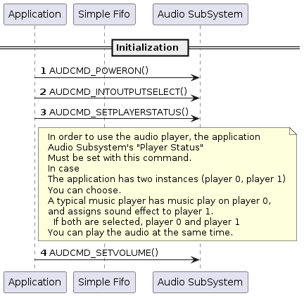
This section describes the music playback initialization and start sequence.
AUDCMD_INITPLAYER, PlayerCommand, AsInitPlayerParam to initialize the playback.
AsPlayerId Sets the ID of the instance. There are two instances as shown below, please set either one.
| Instance number | setting value |
|---|---|
0 |
AS_PLAYER_ID_0 |
1 |
AS_PLAYER_ID_1 |
Please set the codec type of the playback content to MP3 or WAV as shown here:
| Codec type | Setting value |
|---|---|
MP3 |
AS_CODECTYPE_MP3 |
WAV |
AS_CODECTYPE_WAV |
Sets the bit length per sample of playback content to 16 bit and 24bit as shown here:
| bit length | set value |
|---|---|
16 |
AS_BITLENGTH_16 |
24 |
AS_BITLENGTH_24 |
NOTE:
Sets the number of channels of playback content to mono (1ch) or stereo (2ch) as shown here:
| Number of channels | Setting value |
|---|---|
1 |
AS_CHANNEL_MONO |
2 |
AS_CHANNEL_STEREO |
Sets the sampling frequency of the playback content. The setting value that can be set differs for each codec type as shown here:
| Sampling frequency | Set value | Corresponding codec type |
|---|---|---|
16kHz |
AS_SAMPLINGRATE_16000 |
MP3,WAV |
32kHz |
AS_SAMPLINGRATE_32000 |
MP3,WAV |
44.1kHz |
AS_SAMPLINGRATE_44100 |
MP3,WAV |
48kHz |
AS_SAMPLINGRATE_48000 |
MP3,WAV |
88.2kHz |
AS_SAMPLINGRATE_88200 |
WAV |
96kHz |
AS_SAMPLINGRATE_96000 |
WAV |
176.4kHz |
AS_SAMPLINGRATE_176400 |
WAV |
192kHz |
AS_SAMPLINGRATE_192000 |
WAV |
Automatic detection |
AS_SAMPLINGRATE_AUTO |
MP3 |
AS_SAMPLINGRATE_AUTO is used to automatically determine the sampling frequency from Syntax stream syntax.
Currently, it support only MP3.
|
For the high resolution sampling rate, such as, AS_SAMPLINGRATE_88200 , AS_SAMPLINGRATE_96000 , and AS_SAMPLINGRATE_176400 , use the DSP with DualCore and more working area. When trying to perform Dual Decode, 384 kB is required for the DSP area. If necessary, change the SDK configuration and change the DSP area.
|
Specify the absolute path that stores Decoder’s DSP binary image, you can use up to 24 characters.
This is a example when initialize Player0 to play mp3/16bit/Stereo/48kHz audio contents. The decoder which is used for playing audio is placed at BIN directory in SD card.
  AudioCommand command;
  command.header.packet_length = LENGTH_INIT_PLAYER;
  command.header.command_code  = AUDCMD_INITPLAYER;
  command.header.sub_code      = 0x00;
  command.player.player_id                  = AS_PLAYER_ID_0;
  command.player.init_param.codec_type      = AS_CODECTYPE_MP3;
  command.player.init_param.bit_length      = AS_BITLENGTH_16;
  command.player.init_param.channel_number  = AS_CHANNEL_STEREO;
  command.player.init_param.sampling_rate   = AS_SAMPLINGRATE_48000;
  command.player.init_param.dsp_path        = "/mnt/sd0/BIN";
  AS_SendAudioCommand(&command);
Initialize audio output by AUDCMD_INIT_OUTPUTMIXER, AsInitMixerParam command.
AsPlayerId Sets the ID of the instance. There are two instances as shown below, please set either one.
Set postproc type.
AsPostprocTypeThrough    : Through,
AsPostprocTypeUserCustom : User Custom Process,Set path (include file name) of DSP for post process.
If you set AsPostprocTypeThrough to preproc_type, this parameter is not used.
"/mnt/sd0/BINT/POSTPROC" : Put "POSTPROC" binary file on BIN directory in SD card.
"/mnt/spif/POSTPROC"     : Put "POSTPROC" binary file on SPI-FLASH.
Following diagram indicates the position of signal processing by your original DSP.
User customizable signal processing will works on highlighted Customproc and UserCustmDSP.
You can write signal process code which works on the UserCustomDSP.
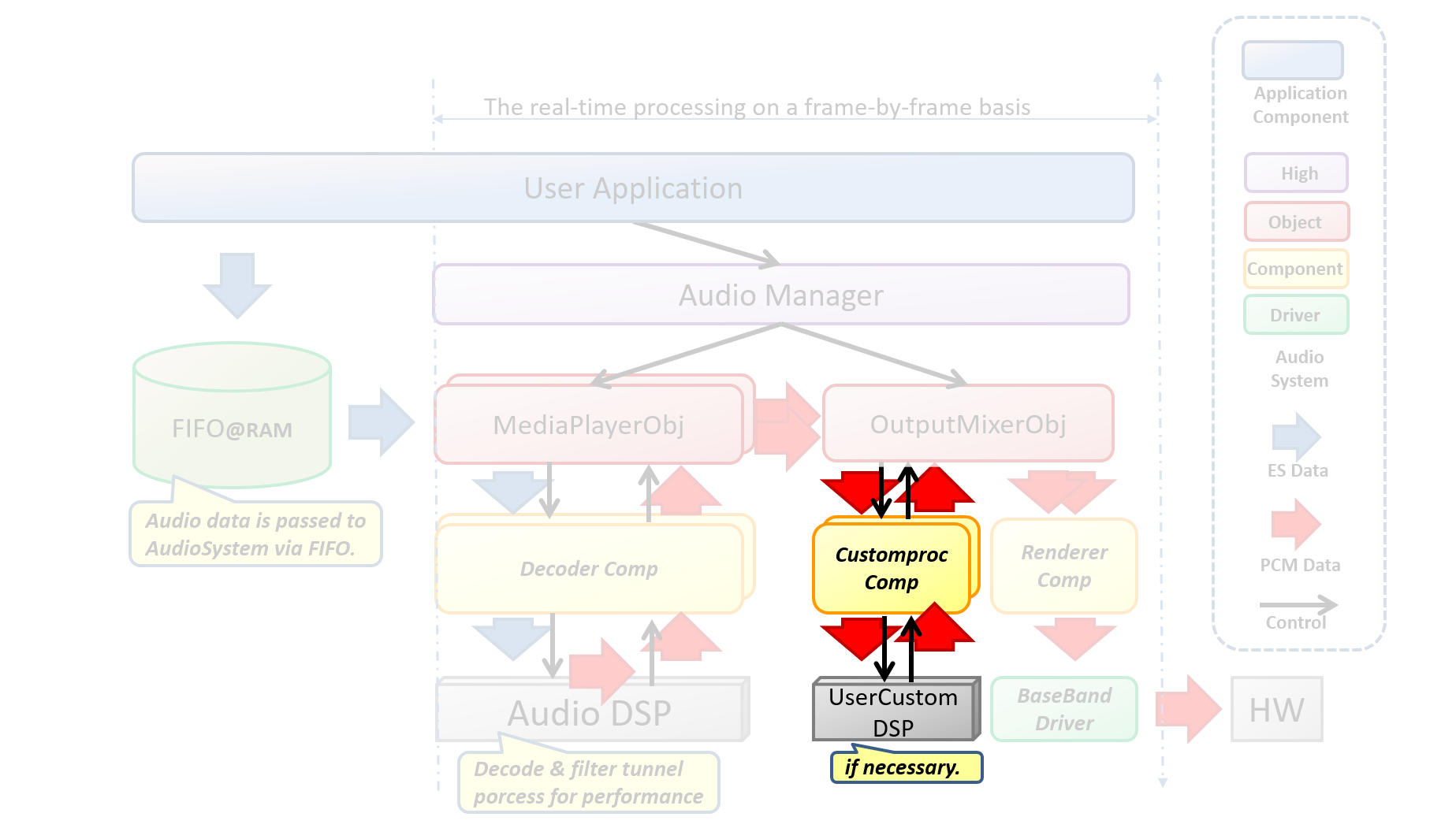
This is a examples when execute signal process to audio data which is out from Player0. The signal processing is done by UserCustomDSP.
AudioCommand command;
Command.header.packet_length = LENGTH_INIT_OUTPUTMIXER;
Command.header.commando_code = AUDCMD_INIT_OUTPUTMIXER;
Command.header.sub_code      = 0x00;
Command.init_mixer_param.player_id     = AS_PLAYER_0;
Command.init_mixer_param.postproc_type = AsPostprocTypeUserCustom;
snprintf(command.init_mixer_param.dsp_path,
         AS_POSTPROC_FILE_PATH_LEN,
         "%s", "/mnt/sd0/BIN/POSTPROC");
AS_SendAudioCommand(&command);AUDCMD_INITMPP, AsInitMediaPlayerPost to initialize DSP for PostProcess.
When postproc_type is set to AsPostprocTypeThrough by AUDCMD_INIT_OUTPUTMIXER, you don’t need to do this operation.
|
AsPlayerId Sets the ID of the instance. There are two instances as shown below, please set either one.
Address of initialize command packet. The format is depend on DSP for PostProcess.
You need to keep the address areas until API returns.
Size of initialize command packet.
This is a example when send initpostcmd as initialize command of DSP.
IniParam initpostcmd;

AudioCommand command;
command.header.packet_length = LENGTH_INITMPP;
command.header.command_code  = AUDCMD_INITMPP;
command.init_mpp_param.player_id        = AS_PLAYER_ID_0;
command.init_mpp_param.initpp_param.addr = reinterpret_cast<uint8_t *>(&initpostcmd);
command.init_mpp_param.initpp_param.size = sizeof(initpostcmd);
AS_SendAudioCommand(&command);AUDCMD_PLAYPLAYER, PlayerCommand will start playing.
When music playback is started, it starts to read the compressed audio data from the FIFO.
For this reason, please input a sufficient amount of compressed audio data to the FIFO before music playback starts.
| If you do not enter a sufficient amount of data in the FIFO at the start, Underflow will occur immediately after starting, and audio playback will stop. |
AsPlayerId Set the ID of the instance. AUDCMD_INITPLAYER initialized instance ID Please set.
| Instance number | setting value |
|---|---|
0 |
AS_PLAYER_ID_0 |
1 |
AS_PLAYER_ID_1 |
This is a example when start playing Player0.
  AudioCommand command;
  command.header.packet_length = LENGTH_PLAY_PLAYER;
  command.header.command_code  = AUDCMD_PLAYPLAYER;
  command.header.sub_code      = 0x00;
  command.player.player_id     = AS_PLAYER_ID_0;
  AS_SendAudioCommand(&command);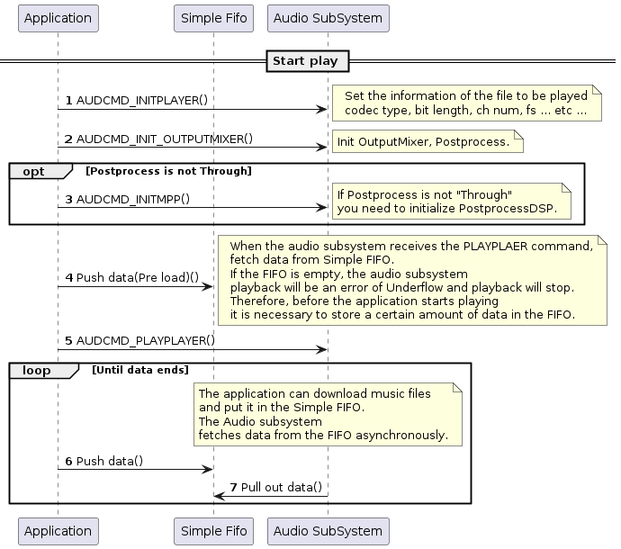
This section describes the sequence of audio playback stop.
AUDCMD_PLAYPLAYER, PlayerCommand, AsStopPlayerParam to stop playback.
AsPlayerId Set the ID of the instance. AUDCMD_PLAYPLAYER Please specify the instance ID you want to stop playback with. It must be the same as started instance ID.
| Instance number | setting value |
|---|---|
0 |
AS_PLAYER_ID_0 |
1 |
AS_PLAYER_ID_1 |
AsStopPlayerStopMode Sets the stop mode. There are three types of stop modes: normal stop, ES end stop, and forced stop.
At ES end stop, all data contained in the FIFO will be played and stopped at the stop request time.
Normal stop will stop immediately at the timing of the stop request and the contents of the FIFO will remain.
Forced stop will be published internally when error occurred in Audio Subsystem. Application has no need to use this mode.
| Stop mode | Setting value |
|---|---|
Normal stop |
AS_STOPPLAYER_NORMAL |
Wait ES end |
AS_STOPPLAYER_ESEND |
Forced stop |
AS_STOPPLAYER_FORCIBLY |
This is a examples when stop Player0 normally.
  AudioCommand command;
  command.header.packet_length = LENGTH_STOP_PLAYER;
  command.header.command_code  = AUDCMD_STOPPLAYER;
  command.header.sub_code      = 0x00;
  command.player.player_id     = AS_PLAYER_ID_0;
  command.player.stop_param.stop_mode = AS_STOPPLAYER_NORMAL;
  AS_SendAudioCommand(&command);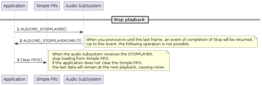
5.3.3.9.2. Build Configurations
In order to use the function of AudioPlayer please follow these instructions:
cd sdk
tools/config.py -m
You need to open the Config menu and configure the following Config.
Select options as shown below:
:(Select audio player application)
[Device Drivers]
  [MMCSD driver support]                   <= Y (If using the SD card)
  [Board specific drivers]
    [CXD56 Audio Driver]                   <= Y

[Application Configuration]
  [Spresense SDK]
    [SDK audio]                            <= Y
      [Audio Utilities]
        [Audio Player]                     <= Y
          [Playlist manager]               <= Y (If use PlayList)

    [Memory Manager]                       <= Y
      [Memory Utilities]                   <= Y

    [ASMP]                                 <= Y
5.3.3.9.3. Error Attentions and Approach
This section shows a list of audio playback error attentions and suggested action to remove the error. See Error Information of Audio SubSystem for more details.
| ID | Attention Code | Attention Level | Approach |
|---|---|---|---|
0x05 |
AS_ATTENTION_SUB_CODE_SIMPLE_FIFO_UNDERFLOW |
WARNING |
This is because AudioSubSystem could not read playback data. Increase the CPU priority of tasks that write playback data to Simple FIFO. |
0x0D |
AS_ATTENTION_SUB_CODE_MEMHANDLE_ALLOC_ERROR |
ERROR |
This is due to insufficient number of segments in the data area. Decrease the priority of tasks other than AudioSubSystem or increase the number of segments in the data area. |
0x0F |
AS_ATTENTION_SUB_CODE_TASK_CREATE_ERROR |
ERROR |
This is due to insufficient heap space. Expand the heap area. |
0x18 |
AS_ECODE_DSP_VERSION_ERROR |
ERROR |
Due to the different version of the DSP binary. Please update the DSP binary image with the file "sdk/modules/audio/dsp". |
0x1A |
AS_ATTENTION_SUB_CODE_STREAM_PARSER_ERROR |
ERROR |
Sync word was not found in the playback file. Make sure that the playback file matches the specified codec. |
0x21 |
AS_ATTENTION_SUB_CODE_ALLOC_HEAP_MEMORY |
WARNING |
Heap area was used instead of pool area. Please confirm that pool area (SRC_WORK_BUF_POOL) of work buffer of sampling rate converter is set. |
|
AS_ATTENTION_SUB_CODE_SIMPLE_FIFO_UNDERFLOW
When this occurs audio playback stops and playback error occurs.
If this happens, immediately issue the AsStopPlayerParam command and change to the playback stop state. Be sure to clear FIFO after transition to play stop. If the application does not do so noise will be generated. |
5.3.3.9.4. DSP install
- DSP binary image install
-
Store the DSP binary image in the path set in Kconfig. The binary image is in
sdk/modules/audio/dsp.Table 16. Binary image required for audio player according to configuration: Image Used memory Binary size MP3DEC
128 kbyte
61 kbyte
WAVDEC
256 kbyte
32 kbyte
The memory size required for execution is used memory.
|
|
When playing high resolution sampling rate, make sure you use 2 cores (192 kB per core) DSP. |
5.3.3.9.5. Audio Player Example
This section will show you an audio player example to playback the music using a simple sampling application .
In build configuration setup Audio player example to Y to use the sample programs for Audio Player.
(audio player:)
[Examples]
  [Audio player example] <= Y
Alternatively,
cd sdk
tools/config.py examples/audio_player
| Audio, Logical sensor example and other multiple samples can not be selected at the same time. If you select more than one, a compile error will appear. |
To set the memory management library (Memory Manager) and the inter-task communication library (Message Library) as follow:
It is necessary to define the MemoryLayout (pool) which is necessary when using the AudioPlayer function.
Definition is done in the MemoaryLayout definition file, and it is possible to generate a header file to be included in the code with the tool.
In the example of Audio Player, do as follow:
cd examples/audio_player/config
python3 mem_layout.conf
"mem_layout.h", "fixed_fence.h" and "pool_layout.h" will be generated.
"mem_layout.h" is referred by msgq_layout tool.
The contents of the MemoaryLayout definition file (mem_layout.conf) are as follow:
FixedAreas
 # name,                  device,     align,        size,         fence
  ["AUDIO_WORK_AREA",     "AUD_SRAM", U_STD_ALIGN,  0x0003e000,   False], # Audio work area
  ["MSG_QUE_AREA",        "AUD_SRAM", U_STD_ALIGN,  0x00001000,   False], # message queue area
  ["MEMMGR_WORK_AREA",    "AUD_SRAM", U_STD_ALIGN,  0x00000200,   False], # MemMgrLite WORK Area
  ["MEMMGR_DATA_AREA",    "AUD_SRAM", U_STD_ALIGN,  0x00000100,   False], # MemMgrLite DATA Area
The explanation of each parameter is as follow:
| Parameter | Description |
|---|---|
name |
area name (name starting with uppercase letters and ending with "_AREA", uppercase letters, numbers, _ can be used) |
device |
Device name of MemoryDevices to reserve space |
align |
Start alignment of the region. Specify a multiple of MinAlign (= 4) except 0 size |
size of the region. Specify a value of a multiple of 4 except 0 |
fence |
The purpose of each name is as follow:
| AUDIO_WORK_AREA |
AudioSubSystem |
| MSG_QUE_AREA |
MessageQueue (fixed name). Do not exceed the size of (MSGQ_END_DRM - MSGQ_TOP_DRAM) of msgq_id.h. |
| MEMMGR_WORK_AREA |
Work area used by Memory Manager (fixed name, fixed size) |
| MEMMGR_DATA_AREA |
Data area used by Memory Manager (fixed name, fixed size) |
Make sure that the total size of each name does not exceed the size of the shared memory secured by mpshm_init(), mpshm_remap().
| Fixed Areas can not be customized |
PoolAreas
 # name,                    area,              align,        pool-size,                    seg,                        fence
  ["DEC_ES_MAIN_BUF_POOL",  "AUDIO_WORK_AREA", U_STD_ALIGN,  U_DEC_ES_MAIN_BUF_POOL_SIZE,  U_DEC_ES_MAIN_BUF_SEG_NUM,  True ],
  ["REND_PCM_BUF_POOL",     "AUDIO_WORK_AREA", U_STD_ALIGN,  U_REND_PCM_BUF_POOL_SIZE,     U_REND_PCM_BUF_SEG_NUM,     True ],
  ["DEC_APU_CMD_POOL",      "AUDIO_WORK_AREA", U_STD_ALIGN,  U_DEC_APU_CMD_POOL_SIZE,      U_DEC_APU_CMD_SEG_NUM,      True ],
  ["SRC_WORK_BUF_POOL",     "AUDIO_WORK_AREA", U_STD_ALIGN,  U_SRC_WORK_BUF_POOL_SIZE,     U_SRC_WORK_BUF_SEG_NUM,     True ],
  ["PF0_PCM_BUF_POOL",      "AUDIO_WORK_AREA", U_STD_ALIGN,  U_POF_PCM_BUF_SIZE,           U_POF_PCM_BUF_SEG_NUM,      True ],
  ["PF1_PCM_BUF_POOL",      "AUDIO_WORK_AREA", U_STD_ALIGN,  U_POF_PCM_BUF_SIZE,           U_POF_PCM_BUF_SEG_NUM,      True ],
  ["PF0_APU_CMD_POOL",      "AUDIO_WORK_AREA", U_STD_ALIGN,  U_DEC_APU_CMD_POOL_SIZE,      U_DEC_APU_CMD_SEG_NUM,      True ],
  ["PF1_APU_CMD_POOL",      "AUDIO_WORK_AREA", U_STD_ALIGN,  U_DEC_APU_CMD_POOL_SIZE,      U_DEC_APU_CMD_SEG_NUM,      True ],
The explanation of each parameter is as follow:
| Parameter | Description |
|---|---|
name |
pool name (name starting with uppercase letters and ending with "_POOL", upper case letters, numbers, _ can be used) |
area |
Area name of FixedArea to be used as pool area. The area must be located in the RAM |
align |
Starting alignment of the pool. Specify a multiple of MinAlign (= 4) except 0 |
pool - size |
size of the pool. A value of a multiple of 4 except 0. In the Basic pool, segment size * number of segments In the final area of each area, RemainderSize indicating the remaining size can be specified. |
seg |
Number of segments. Specify a value between 1 and 255 |
fence |
Specify whether the fence is valid or invalid. This item is ignored when UseFence is False |
The purpose of each name is as follow:
| DEC_ES_MAIN_BUF_POOL |
Buffer area for storing input data for player 0 |
| REND_PCM_BUF_POOL |
Buffer area for output of decoded data for player 0 |
| DEC_APU_CMD_POOL |
Command area for DSP (Decoder) |
| SRC_WORK_BUF_POOL |
Work buffer area for DSP(SamplingRateConverter) |
| PF0_PCM_BUF_POOL |
Buffer area for PostFilter 0 |
| PF1_PCM_BUF_POOL |
Buffer area forPostFilter1 |
| PF0_APU_CMD_POOL |
Command area for PostFilter 0 |
| PF1_APU_CMD_POOL |
Command area for PostFilter1 |
|
Refer to examples/audio_player/config/mem_layout.conf for details of each definition. If the setting changes, please use the tool to generate a new header file. |
It is necessary to define the MessageQueue which is necessary when using the AudioPlayer function. Definition is done in the MessageQueueLayout definition file, and you can generate a header file to be included in the code with the tool.
In the example of Audio Player, do as follow:
cd examples/audio_player/config
python3 msgq_layout.conf
"msgq_id.h" and "msgq_pool.h" will be generated.
Copy all of the generated header files into include directory.
cd examples/audio_player/config
mv *.h ../include
The description contents of the MessageQueueLayout definition file (msgq_layout.conf) are as follow:
MsgQuePool
 # ID,                        n_size  n_num  h_size  h_nums
  ["MSGQ_AUD_MNG",            88,     30,    0,      0],
  ["MSGQ_AUD_APP",            64,      2,    0,      0],
  ["MSGQ_AUD_DSP",            20,      5,    0,      0],
  ["MSGQ_AUD_PFDSP0",         20,      5,    0,      0],
  ["MSGQ_AUD_PFDSP1",         20,      5,    0,      0],
  ["MSGQ_AUD_PLY0",           48,      5,    0,      0],
  ["MSGQ_AUD_PLY1",           48,      5,    0,      0],
  ["MSGQ_AUD_OUTPUT_MIX",     48,      8,    0,      0],
  ["MSGQ_AUD_RND_PLY0",       32,     16,    0,      0],
  ["MSGQ_AUD_RND_PLY0_SYNC",  16,      8,    0,      0],
  ["MSGQ_AUD_RND_PLY1",       32,     16,    0,      0],
  ["MSGQ_AUD_RND_PLY1_SYNC",  16,      8,    0,      0],
The explanation of each parameter is as follow:
| Parameter | Description |
|---|---|
ID |
Specify the name of the message queue pool ID as a character string beginning with "MSGQ_". |
n_size |
Number of bytes of each element of the normal priority queue (8 or more and 512 or less). Specify fixed header length (8 bytes) + parameter length as a multiple of 4. |
n_num |
Number of elements of normal priority queue (1 or more and 16384 or less). |
h_size |
Number of bytes (0 or 8 to 512 inclusive) for each element of the high priority queue. Specify 0 when not in use. |
h_num |
Number of elements in the high priority queue (0 or 1 to 16384 or less). Specify 0 when not in use. |
For each ID, see Audio Player Message ID of Audio Player Functions.
Since n_size is the optimum value, please do not change.
There is no need to change n_num, but when using the AudioPlayer function with other Application, it may be necessary to increase the value considering the load.
Use h_size and h_nums when you want to process the AudioPlayer function preferentially.
|
Refer to examples/audio_player/config/msgq_layout.conf for details on each definition. If the settings change, please use the tool to generate a new header file. |
| sampling rate | PCM bit length | channel number | CPU frequency lock | |
|---|---|---|---|---|
mp3 |
16kHz / 32kHz / 44.1kHz / 48kHz |
16bit |
1ch / 2ch |
High voltage |
wav (Low Power) |
16kHz / 32kHz 44.1kHz / 48kHz |
16bit |
1ch / 2ch |
Low voltage |
wav |
48kHz / 88.4kHz / 96kHz / 176.4kHz / 196kHz |
16bit / 24bit |
1ch / 2ch |
High voltage |
-
Preparation
- Music file
-
To run the audio player application, you need a music file. Create an
AUDIO/directory on the root directory of the SD card and copy music files to this directory. - Playlist
-
To play music files, you need a playlist. This is a file that contains track databases in CSV data format. You can add new tracks to this file or delete tracks from this file. Create a
PLAYLIST/directory on the root directory of the SD card and copy theTRACK_DB.CSVfiles to this directory.The track database has this format:
[filename],[artist],[album],[channel number],[bit length],[sampling rate],[file format]
ABC.mp3,artist1,album1,2,16,44100,mp3
| The example is a premise to use Playlist. Only the first line of the list is played. |
Start the player application from NuttShell.
nsh> player
player The application starts and the following log is displayed.
Start Audio Player example
Playback of the first file of PlayList starts.
|
If the SD card can not be recognized, the following error log is displayed. Check the status of sd card. Error: /mnt/sd0/AUDIO directory path error. check the path! Error: app_open_contents_dir() failure. Exit AudioPlayer example If PlayList can not be recognized, the following error log is displayed. Please check that the path of PlayList is correct. Track db(playlist) /mnt/sd0/PLAYLIST/TRACK_DB.CSV open error. check paths and files! /mnt/sd0/PLAYLIST/alias_list_alltrack.bin cannot opened. If PlayFile can not be recognized, the following error log is displayed. Please check whether path has File or whether the PlayList matches the File name. Error: /mnt/sd0/AUDIO/***.mp3 open error. check paths and files! Error: app_start_player() failure. If you do not set the pool area(SRC_WORK_BUF_POOL) of work buffer for sampling rate converter, the following warning log is displayed. Heap space is used instead of pool area and fragmentation may occur. Please Set SRC_WORK_BUF_POOL with AS_CreatePlayerMulti. Attention: module[5] attention id[1]/code[33] (objects/media_player/media_player_obj.cpp L****) |
After 10 seconds playback, the Player application will end.
Exit AudioPlayer example
5.3.3.10. Audio Recorder functions
A simple data flow of Audio Recorder is shown below.
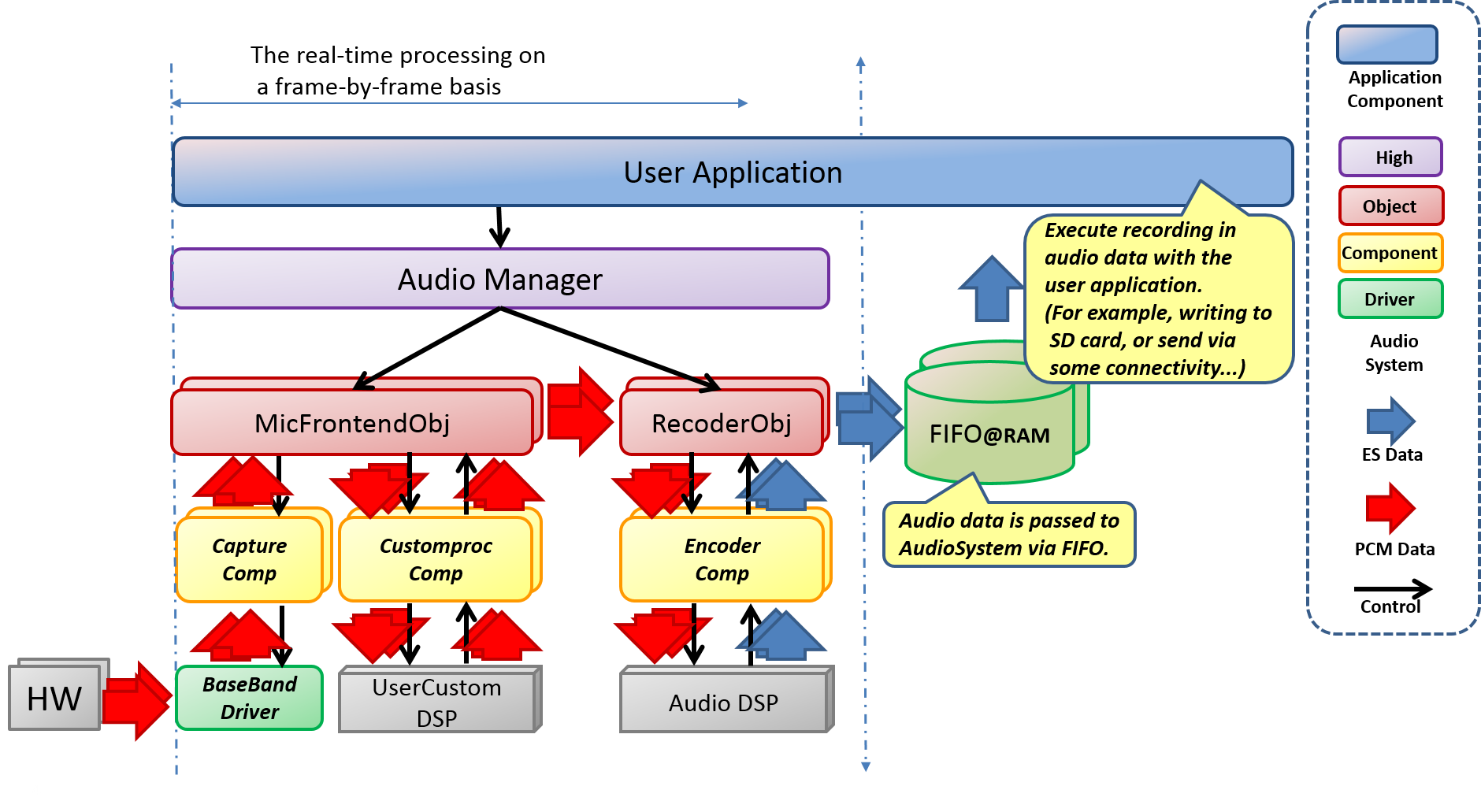
When the Audio SubSystem operates with RecorderMode, the User Application needs to prepare a FIFO for storing audio data. When recording audio data starts, audio data accumulates in this FIFO after a certain period of operation. This audio data is encoded in the specified compression format and should be read out from the FIFO appropriately so that it does not overflow from the FIFO so that continuous audio data can be acquired.
Although Recorder can capture two inputs from the HW, at the present time, it does not support the function to generate two instances and record two lines.
The User Application implements the Recorder application by processing this voice according to the requirements of each system (for example, exporting it to Storage, sending it to the Connectivity module, cloud processing, etc.).
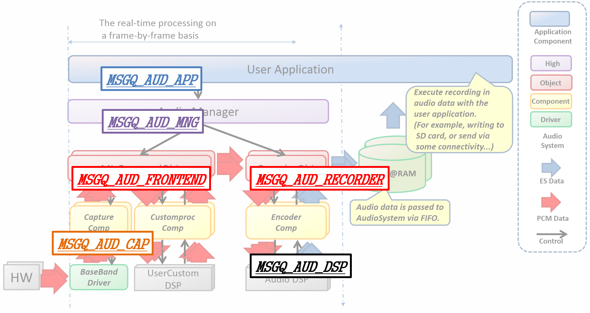
The inside of the data flow communicates with Messages. Each message communication has an ID for each client. In the case of Audio Recorder, based on the example Layout in the example, the ID will be as follows.
User Application           : MSGQ_AUD_APP
Audio Manager              : MSGQ_AUD_MNG
Audio Frontend             : MSGQ_AUD_FRONTEND
Audio Recorder             : MSGQ_AUD_RECORDER
Audio Capture Component    : MSGQ_AUD_CAP
Audio DSP                  : MSGQ_AUD_DSP
※MSGQ_AUD_CAP_SYNC will be deleted.
In addition, the data area of each data is as follow.
PCM (Input) Data Buffer    : INPUT_BUF_POOL
ES Data Buffer (for DSP)   : ES_BUF_POOL
PreProcess DSP command     : PRE_APU_CMD_POOL
Audio Encoder DSP Command  : ENC_APU_CMD_POOL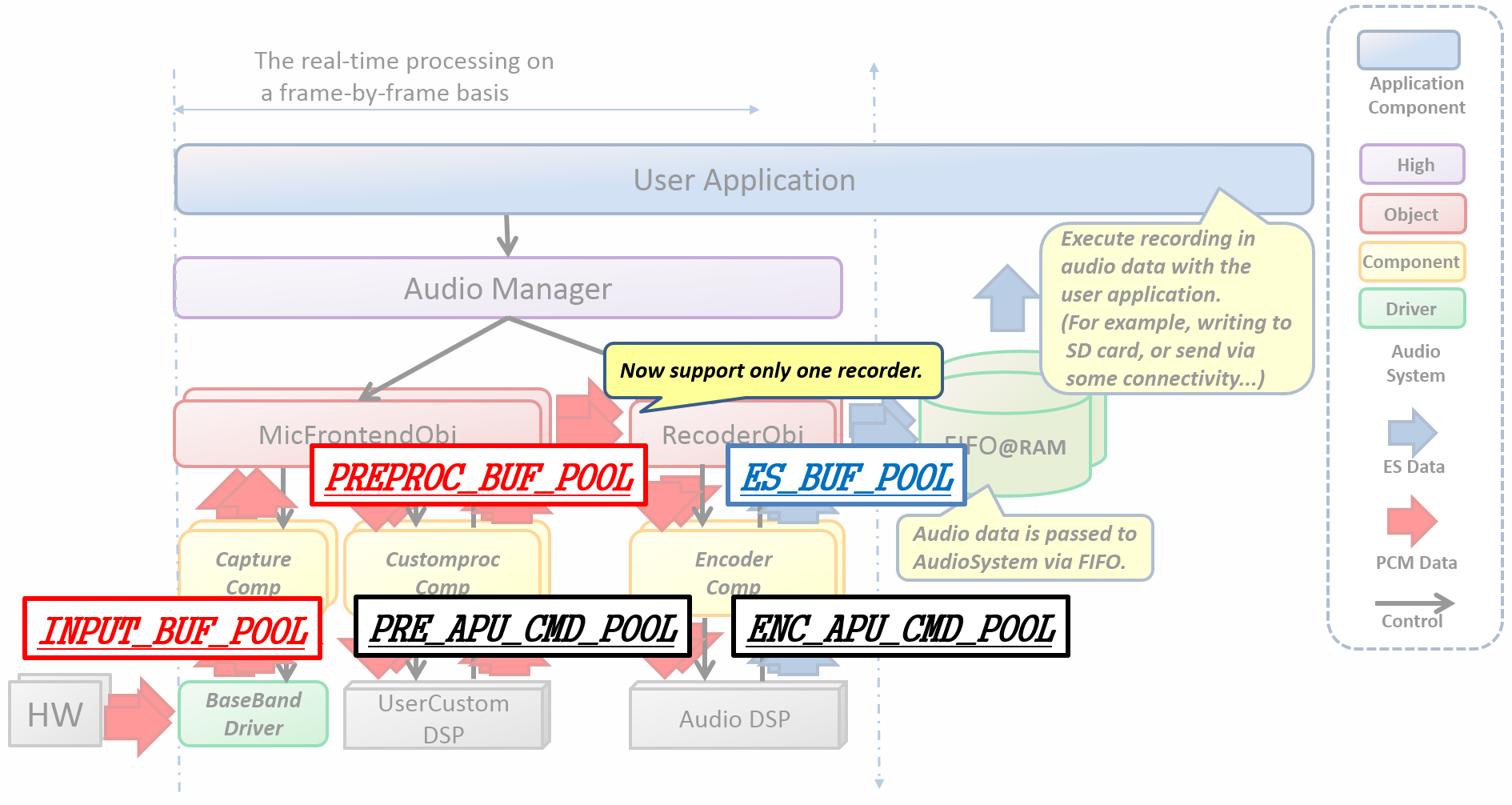
These IDs must be specified when generating.
5.3.3.10.1. How to use
"AudioManager", "MicFrontendObject", "MediaRecorderObject", "CaptureComponent" are software components designed to control audio subsystems and implement an Audio Recorder.
When the necessary objects have been generated, initialization processing such as audio HW setting, power on, change of operation mode, etc. is performed in order to perform Recorder operation.
It can be realized by issuing the following commands in order.
To turn on the audio block, issue the AUDCMD_POWERON, PowerOnParam command to turn on the power and change the state of the Audio Sub system to the Ready state.
The enable_sound_effect is fixed to AS_DISABLE_SOUNDEFFECT.
AS_DISABLE_SOUNDEFFECT::SoundEffect invalidAudioCommand command;
command.header.packet_length = LENGTH_POWERON;
command.header.command_code = AUDCMD_POWERON;
command.header.sub_code = 0x00;
command.power_on_param.enable_sound_effect = AS_DISABLE_SOUNDEFFECT;
AS_SendAudioCommand(&command);AUDCMD_INITMICGAIN Set Mic’s Gain.
In the case of an analog microphone, the value obtained by multiplying the dB value by 10. It can be set in the range of 0 (0.0 dB) to 210 (21.0 dB) in multiples of 5. The default value is 0.0 dB.
+
In the case of a digital microphone, the value obtained by multiplying the dB value by 100. It can be set within the range of -7850 (-78.50 dB) to 0 (0.00 dB). The default value is -78.50 dB.
If you do not want to change the value of Gain, please specify AS_MICGAIN_HOLD.
This is a example when add 21dB gain to 1ch to 4ch. 5ch to 8ch are not changed gain.
AudioCommand command;
command->header.packet_length = LENGTH_INITMICGAIN;
command->header.command_code = AUDCMD_INITMICGAIN;
command->header.sub_code = 0;
command->init_mic_gain_param.mic_gain[0] = 210;
command->init_mic_gain_param.mic_gain[1] = 210;
command->init_mic_gain_param.mic_gain[2] = 210;
command->init_mic_gain_param.mic_gain[3] = 210;
command->init_mic_gain_param.mic_gain[4] = AS_MICGAIN_HOLD;
command->init_mic_gain_param.mic_gain[5] = AS_MICGAIN_HOLD;
command->init_mic_gain_param.mic_gain[6] = AS_MICGAIN_HOLD;
command->init_mic_gain_param.mic_gain[7] = AS_MICGAIN_HOLD;
AS_SendAudioCommand(&command);| Refer to "examples/audio_recorder/config/msgq_layout.conf" for the definition of details. |
Each element of mic_gain[] corresponds to the ID of the microphone. The ID of the microphone is set by the value of "MIC channel select map" of Config. The default setting is the analog mic 1/2/3/4.
Below is the information of configuration.
[Device Drivers]
[Board specific drivers]
[CXD56 Audio Driver]
[Audio baseband config settings]
[CXD5247 settings]
(0xFFFF4321) MIC channel select map
The value of "MIC channel select map" indicates the ID of the MIC every 4 bits. The relationship between the element of mic_gain and the bit field of "MIC channel select map" is as follow.
| element of mic_gain | [7] | [6] | [5] | [4] | [3] | [2] | [1] | [0] |
|---|---|---|---|---|---|---|---|---|
bit field |
31 - 28 |
27 - 24 |
23 - 20 |
19 - 16 |
15 - 12 |
11 - 8 |
7 - 4 |
3 - 0 |
The relationship between the value (ID) of "MIC channel select map" and the type of microphone is as follow.
| HEX value (ID) | Microphone type |
|---|---|
0x1 |
CXD5247 Analog microphone 1 |
0x2 |
CXD5247 Analog microphone 2 |
0x3 |
CXD5247 Analog microphone 3 |
0x4 |
CXD5247 Analog microphone 4 |
0x5 |
CXD5247 Digital microphone 1 |
0x6 |
CXD5247 Digital microphone 2 |
0x7 |
CXD5247 Digital microphone 3 |
0x8 |
CXD5247 Digital microphone 4 |
0x9 |
CXD5247 Digital microphone 5 |
0xA |
CXD5247 Digital microphone 6 |
0xB |
CXD5247 Digital microphone 7 |
0xC |
CXD5247 Digital microphone 8 |
Please set the microphone to use from element 0 in order. It is not possible to skip element numbers. Mixing of analog mic and digital microphone is not supported. To set the analog microphone please set element 0-3. If the element is an even number, it is the L channel, and if the element is odd, it becomes the R channel.
AUDCMD_SETRECORDERSTATUS Transitions the state of AudioSubSystem to Recorder state.
Specify the input device to be recorded. It is necessary to match with the microphone type set with AUDCMD_INITMICGAIN.
AS_SETRECDR_STS_INPUTDEVICE_MIC_A : CXD5247: analog microphone
AS_SETRECDR_STS_INPUTDEVICE_MIC_D : CXD5247: digital microphoneIt is fixed at 0 at this time.
Specify the output destination device of the encoded Elementary stream (ES) data.
At the moment only RAM device output is supported.
AS_SETRECDR_STS_OUTPUTDEVICE_RAM : Output to RAM deviceSpecify the handler of Simple FIFO where output (Encoded ES data) is stored.
simple_fifo_handler is obtained with CMN_SimpleFifoInitialize().
This is a example when record mic input to SimpleFIFO.
AudioCommand command;
command.header.packet_length = LENGTH_SET_RECORDER_STATUS;
command.header.command_code = AUDCMD_SETRECORDERSTATUS;
command.header.sub_code = 0x00;
command.set_recorder_status_param.input_device = AS_SETRECDR_STS_INPUTDEVICE_MIC_A;
command.set_recorder_status_param.input_device_handler = 0x00;
command.set_recorder_status_param.output_device = AS_SETRECDR_STS_OUTPUTDEVICE_RAM;
command.set_recorder_status_param.output_device_handler = &s_recorder_info.fifo.output_device;
AS_SendAudioCommand(&command);The audio recording start sequence.
AUDCMD_INIT_MICFRONTEND, MicFrontendCommand, AsInitMicFrontEnd to set the mic frontend operation.
AS_CHANNEL_MONO : Monoral
AS_CHANNEL_STEREO : Stereo
AS_CHANNEL_4CH : 4ch
AS_CHANNEL_6CH : 6ch
AS_CHANNEL_8CH : 8chAS_BITLENGTH_16 : 16bit
AS_BITLENGTH_24 : 24bit/* Set samples num per a frame. */Set output sampling rate from MicFrontend.
Effective only When preproc_type is set to AsMicFrontendPreProcSrc .
AS_SAMPLINGRATE_8000 : 8kHz
AS_SAMPLINGRATE_16000 : 16kHz
AS_SAMPLINGRATE_44100 : 44.1kHz
AS_SAMPLINGRATE_48000 : 48kHz
...
...
AS_SAMPLINGRATE_192000 : 192kHzSet pre process type.
AsMicFrontendPreProcThrough : Through
AsMicFrontendPreProcSrc : Sampling Rate Converter
AsMicFrontendPreProcUserCustom : User Custom Process
When you set AsMicFrontendPreProcSrc , You need SRC binary file which is placed at sdk/modules/audio/DSP/ .
|
Set path (include file name) of DSP for pre process.
If you set AsMicFrontendPreProcThrough to preproc_type, this parameter is not used.
"/mnt/sd0/BIN/PREPROC" : Put "PREPROC" binary file on BIN directory in SD card. "/mnt/spif/SRC" : Put "SRC" binary file on SPI-FLASH.
Set audio data destination from MicFrontend.
AsMicFrontendDataToRecorder : Send to Recorder
AsMicFrontendDataToRecognizer : Send to RecognizerFollowing diagram indicates the position of signal processing by your original DSP.
User customizable signal processing will works on highlighted Customproc and UserCustmDSP.
You can write signal process code which works on the UserCustomDSP.
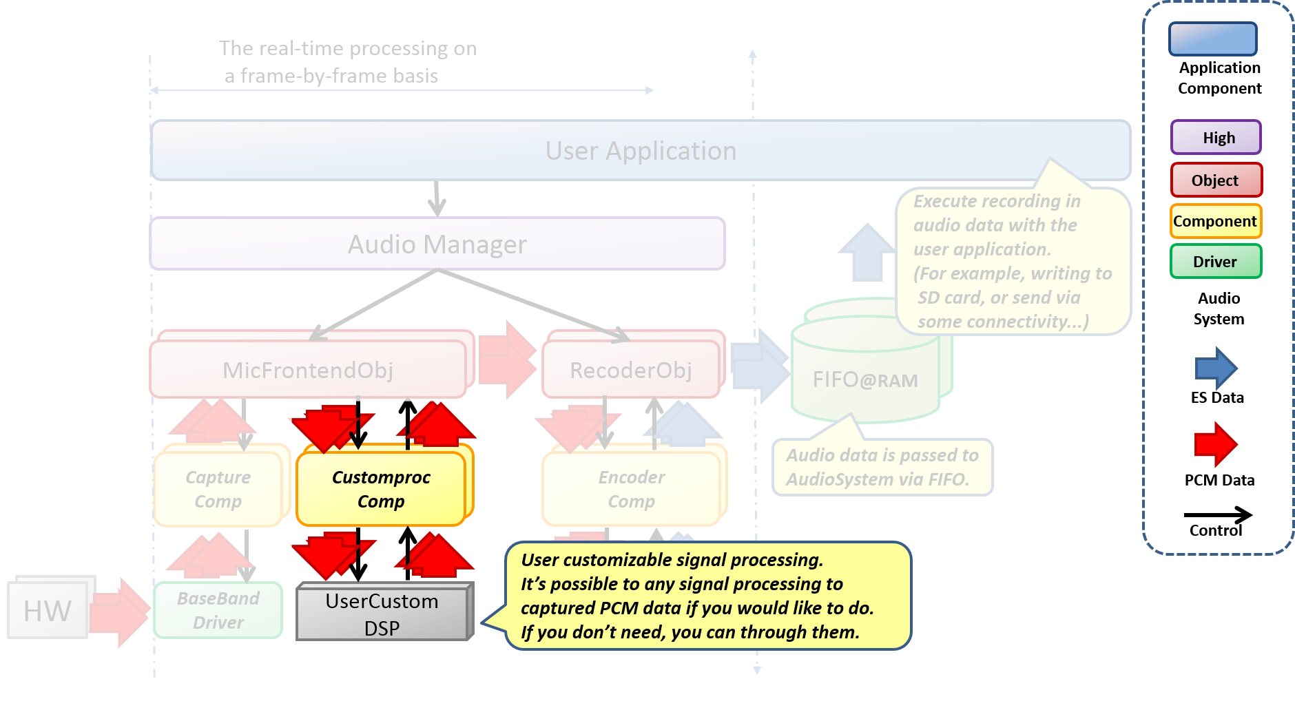
This is a example when capture "Mono/16bit/768samples per frame" audio data.
Pre process is done by User Custom DSP, and the DSP binary file is placed on BIN directory in SD card.
Captured audio data is used for recording.
AudioCommand command;
command.header.packet_length = LENGTH_INIT_MICFRONTEND;
command.header.command_code = AUDCMD_INIT_MICFRONTEND;
command.header.sub_code = 0x00;
command.init_micfrontend_param.ch_num = AS_CHANNEL_MONO
command.init_micfrontend_param.bit_length = AS_BITLENGTH_16;
command.init_micfrontend_param.sample = 768;
command.init_micfrontend_param.outfs = AS_SAMPLINGRATE_16000;
command.init_micfrontend_param.preproc_type = AsMicFrontendPreProcUserCustom;
snprintf(command.init_micfrontend_param.preprocess_dsp_path,
AS_RECOGNIZER_FILE_PATH_LEN,
"%s", "/mnt/sd0/BIN/PREPROC");
command.init_micfrontend_param.data_dest = AsMicFrontendDataToRecorder;AUDCMD_INIT_PREPROCESS_DSP, AsInitRecorderParam to initialize DSP for PreProcess.
When preproc_type is set to AsMicFrontendPreProcThrough by AUDCMD_INIT_MICFRONTEND, you don’t need to do this operation.
|
Address of initialize command packet. The format is depend on DSP for PreProcess.
You need to keep the address areas until API returns.
Size of initialize command packet.
This is a example when send s_initparam as initialize command of DSP.
static uint8_t s_initparam = 0;
AudioCommand command;
command.header.packet_length = LENGTH_INIT_PREPROCESS_DSP;
command.header.command_code = AUDCMD_INIT_PREPROCESS_DSP;
command.header.sub_code = 0x00;
command.init_preproc_param.packet_addr = reinterpret_cast<uint8_t *>(&s_initparam);
command.init_preproc_param.packet_size = sizeof(s_initparam);
AS_SendAudioCommand(&command);AUDCMD_INITREC, RecorderCommand, AsInitRecorderParam to set the recording operation.
AS_SAMPLINGRATE_8000 : 8kHz
AS_SAMPLINGRATE_16000 : 16kHz
AS_SAMPLINGRATE_48000 : 48kHzAS_CHANNEL_MONO : Monoral
AS_CHANNEL_STEREO : Stereo
AS_CHANNEL_4CH : 4ch
AS_CHANNEL_6CH : 6ch
AS_CHANNEL_8CH : 8chAS_BITLENGTH_16 : 16bit
AS_BITLENGTH_24 : 24bitAS_CODECTYPE_MP3 : MP3
AS_CODECTYPE_LPCM : LinearPCMValid only when MP3 encoding
AS_BITRATE_8000 : 8000
AS_BITRATE_16000 : 16000
AS_BITRATE_24000 : 24000
AS_BITRATE_32000 : 32000
AS_BITRATE_40000 : 40000
AS_BITRATE_48000 : 48000
AS_BITRATE_56000 : 56000
AS_BITRATE_64000 : 64000
AS_BITRATE_80000 : 80000
AS_BITRATE_96000 : 96000
AS_BITRATE_112000 : 112000
AS_BITRATE_128000 : 128000
AS_BITRATE_144000 : 144000
AS_BITRATE_160000 : 160000
AS_BITRATE_192000 : 192000
AS_BITRATE_224000 : 224000
AS_BITRATE_256000 : 256000
AS_BITRATE_320000 : 320000Specify the absolute path that stores the Decoder’s DSP image. Maximum of 24 characters.
| The combination of input device and number of channels is limited. |
| Input | number of channels |
|---|---|
Mic |
1 ch (Monoral), 2 ch (Stereo), 4 ch (* 1), 6 ch (* 2), 8 ch (* 2) |
-
(* 1. LPCM only)
-
(* 2. Only when using LPCM and DigitalMic)
| The combination of Codec, bit length, sampling frequency, and bit rate is limited. |
| Codec | bit length | sampling frequency | bit rate |
|---|---|---|---|
MP3 |
16 bit |
16 kHz |
8000 (*1), 16000 - 160000 |
48 kHz |
32000 - 320000 |
||
LPCM |
16 bit |
16 kHz, 48 kHz |
- |
24 bit (*2) |
16 kHz, 48 kHz, 192 kHz (*2) |
- |
-
(*1. when 1ch is specified)
-
(*2. Designated HiResolution mode)
This is a example when record 16kHz/Mono/LPCM. The DSP binary file for encoding is placed on BIN directory in SD card.
AudioCommand command;
command.header.packet_length = LENGTH_INIT_RECORDER;
command.header.command_code = AUDCMD_INITREC;
command.header.sub_code = 0x00;
command.recorder.init_param.sampling_rate = AS_SAMPLINGRATE_16000;
command.recorder.init_param.channel_number = AS_CHANNEL_MONO;
command.recorder.init_param.bit_length = AS_BITLENGTH_16;
command.recorder.init_param.codec_type = AS_CODECTYPE_LPCM;
command.recorder.init_param.bitrate = AS_BITRATE_8000;
command.recorder.init_param.computational_complexity = AS_INITREC_COMPLEXITY_0
command.recorder.init_param.dsp_path = "/mnt/sd0/BIN";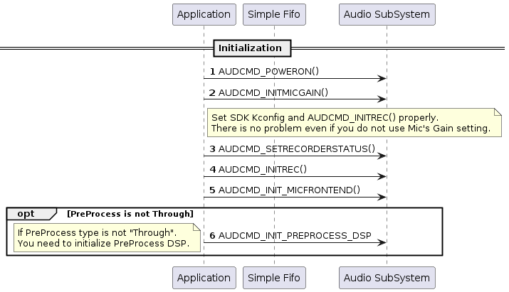
AUDCMD_STARTREC, RecorderCommand Recording starts.
Once you start recording, the Audio System writes the ES data to the FIFO. In order to correctly record audio data, it is necessary to read the written data before the FIFO overflows. Data writing will be notified, so please read it in response to this event as appropriate.
| For details, please refer to "examples/audio_recorder/config/msgq_layout.conf". |
| When the FIFO is Full, the Audio System can not write, and discards audio data that can not be written. Therefore, if this occurs during recording the audio data will be discontinuous audio. |
AudioCommand command;
command.header.packet_length = LENGTH_START_RECORDER;
command.header.command_code = AUDCMD_STARTREC;
command.header.sub_code = 0x00;
AS_SendAudioCommand(&command)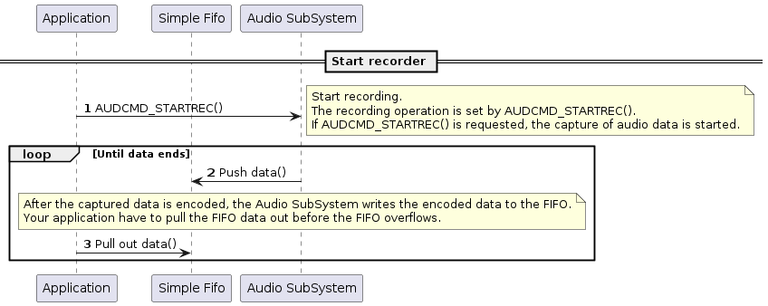
- Stop Recorder
-
AUDCMD_STOPREC, RecorderCommand Stop recording
Recorder encodes up to the audio data that was captured when receiving the stop instruction.
AudioCommand command;
command.header.packet_length = LENGTH_STOP_RECORDER;
command.header.command_code = AUDCMD_STOPREC;
command.header.sub_code = 0x00;
AS_SendAudioCommand(&command)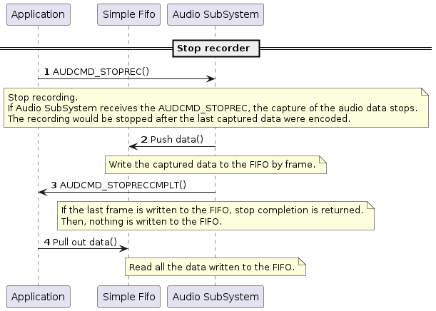
5.3.3.10.2. Build Configurations
To use AudioRecorder’s features
cd sdk/ tools/config.py -m
You need to open the Config menu and set the following Config.
Select options in below:
:(Select audio recorder)
[Device Drivers]
[MMCSD driver support] <= Y (If using the SD card)
[Board specific drivers]
[CXD56 Audio Driver] <= Y
[Application Configuration]
[Spresense SDK]
[SDK audio] <= Y
[Audio Utilities]
[Audio Recorder] <= Y
[Memory Manager] <= Y
[Memory Utilities] <= Y
[ASMP] <= Y
5.3.3.10.3. Error Attentions and Approach
This section shows a list of audio recording error attentions and suggested action to remove the error. See Error Information of Audio SubSystem for more details.
| ID | Attention Code | Attention Level | Approach |
|---|---|---|---|
0x06 |
AS_ATTENTION_SUB_CODE_SIMPLE_FIFO_OVERFLOW |
WARNING |
This is because AudioSubSystem could not write recording data to SimpleFIFO. Increase the CPU priority of tasks that read recording data to Simple FIFO. |
0x0D |
AS_ATTENTION_SUB_CODE_MEMHANDLE_ALLOC_ERROR |
ERROR |
This is due to insufficient number of segments in the data area. Decrease the priority of tasks other than AudioSubSystem or increase the number of segments in the data area. |
0x0F |
AS_ATTENTION_SUB_CODE_TASK_CREATE_ERROR |
ERROR |
This is due to insufficient heap space. Expand the heap area. |
0x18 |
AS_ATTENTION_SUB_CODE_DSP_VERSION_ERROR |
ERROR |
Due to the different version of the DSP binary. Please update the DSP binary image with the file "sdk/modules/audio/dsp". |
5.3.3.10.4. DSP install
- DSP binary image install
-
Store the DSP binary image in the path set in Kconfig. The binary image is in
sdk/modules/audio/dsp.
| Image | Used memory | Binary size |
|---|---|---|
MP3ENC |
256 kbyte |
111 kbyte |
SRC (Sampling Rate Converter) |
128 kbyte |
21 kbyte |
The memory size required for execution is used memory.
|
| Although LPCM does not require compression processing, loading of the DSP of Sampling Rate Converter (SRC) is necessary because frequency conversion processing is necessary. |
5.3.3.10.5. Audio Recorder Example
There is a simple Recorder Example, and you can use to check the operation of Recorder.
To use the sample program of Audio Recorder, please make the following settings.
Read config of audio_recorder.
cd sdk/ tools/config.py examples/audio_recorder
Make sure Audio recorder is enabled.
tools/config.py -m
(audio recorder:)
[Examples]
[Audio recorder example] <= Y| Audio & Logical sensor example and other multiple samples can not be selected at the same time. If you select more than one, a compile error will appear. |
For details, see the Start Rec item.
It is necessary to define the MemoryLayout(pool) when using the AudioRecorder function.
Definition is done in the MemoaryLayout definition file, and it is possible to generate a header file to be included in the code with the tool.
example of audio recorder is performed as follows.
cd examples/audio_recorder/config python3 mem_layout.conf
"mem_layout.h", "fixed_fence.h" and "pool_layout.h" will be generated.
"mem_layout.h" is referred by msgq_layout tool.
The contents of the Memory Layout definition file (mem_layout.conf) are as follow.
FixedAreas
# name, device, align, size, fence
["AUDIO_WORK_AREA", "AUD_SRAM", U_STD_ALIGN, 0x0003d000, False],
["MSG_QUE_AREA", "AUD_SRAM", U_STD_ALIGN, 0x00002000, False],
["MEMMGR_WORK_AREA", "AUD_SRAM", U_STD_ALIGN, 0x00000200, False],
["MEMMGR_DATA_AREA", "AUD_SRAM", U_STD_ALIGN, 0x00000100, False],The explanation of each parameter is as follow.
| Parameter | Description |
|---|---|
name |
area name (name starting with uppercase letters and ending with "_AREA", uppercase letters, numbers, _ can be used) |
device |
Device name of MemoryDevices to reserve space |
align |
Start alignment of the region. Specify a multiple of MinAlign(= 4) except 0 |
size |
Size of the region. Specify a value of a multiple of 4 except 0 |
fence |
Specify whether fence is enabled or disabled (This item is ignored when UseFence is False) |
The purpose of each name is as follow.
| AUDIO_WORK_AREA |
Used by AudioSubSystem |
| MSG_QUE_AREA |
Used by MessageQueue (fixed name). Do not exceed the size of (MSGQ_END_DRM - MSGQ_TOP_DRAM) of msgq_id.h. |
| MEMMGR_WORK_AREA |
Work area used by Memory Manager (fixed name, fixed size) |
| MEMMGR_DATA_AREA |
Data area used by Memory Manager (fixed name, fixed size) |
Make sure that the total size of each name does not exceed the size of the shared memory secured by mpshm_init(), mpshm_remap().
| Fixed Areas can not be customized |
PoolAreas
# name, area, align, pool-size, seg, fence
["ES_BUF_POOL", "AUDIO_WORK_AREA", U_STD_ALIGN, 0x0000F000, 5, True ],
["PREPROC_BUF_POOL", "AUDIO_WORK_AREA", U_STD_ALIGN, 0x0000F000, 5, True ],
["INPUT_BUF_POOL", "AUDIO_WORK_AREA", U_STD_ALIGN, 0x0000F000, 5, True ],
["ENC_APU_CMD_POOL", "AUDIO_WORK_AREA", U_STD_ALIGN, 0x00000114, 3, True ],
["SRC_APU_CMD_POOL", "AUDIO_WORK_AREA", U_STD_ALIGN, 0x00000114, 3, True ],
["PRE_APU_CMD_POOL", "AUDIO_WORK_AREA", U_STD_ALIGN, 0x00000114, 3, True ],The explanation of each parameter is as follow.
| Parameter | Description |
|---|---|
name |
pool name (name starting with uppercase letters and ending with "_POOL", upper case letters, numbers, _ can be used) |
area |
Area name of FixedArea to be used as pool area. The area must be located in the RAM |
align |
Starting alignment of the pool. Specify a multiple of MinAlign(= 4) except 0 |
pool - size |
size of the pool. A value of a multiple of 4 except 0. In the Basic pool, segment size * number of segments |
seg |
Number of segments. Specify a value between 1 and 255 |
fence |
Specify whether the fence is valid or invalid. This item is ignored when UseFence is False |
The purpose of each name is as follow.
| ES_BUF_POOL |
Storage buffer area of 窶銀逆he result of encoding input speech |
| INPUT_BUF_POOL |
Input storage buffer area for audio data to be recorded |
| ENC_APU_CMD_POOL |
Encoder Communication with DSP command buffer area |
| SRC_APU_CMD_POOL |
SRC Communication with DSP Command buffer area communication |
|
Refer to examples/audio_recorder/config/mem_layout.conf for details on each definition. ꀀꀀꀀꀀꀀꀀIf the setting changes, please use the tool to generate a new header file. |
It is necessary to define the MessageQueue that is required when using the AudioRecorder function. The definition is done in the MessageQueueLayout definition file, and you can generate a header file to be included in the code with the tool.
example of audio recorder is performed as follows.
cd examples/audio_recorder/config python3 msgq_layout.conf
"msgq_id.h" and "msgq_pool.h" will be generated.
Copy all of the generated header files into include directory.
cd examples/audio_recorder/config mv *.h ../include
The description contents of the MessageQueueLayout definition file (msgq_layout.conf) are as follows.
MsgQuePool
# ID, n_size n_num h_size h_num
["MSGQ_AUD_MGR", 88, 30, 0, 0],
["MSGQ_AUD_APP", 64, 2, 0, 0],
["MSGQ_AUD_DSP", 20, 5, 0, 0],
["MSGQ_AUD_RECORDER", 48, 5, 0, 0],
["MSGQ_AUD_CAP", 24, 16, 0, 0],
["MSGQ_AUD_CAP_SYNC", 16, 8, 0, 0],
["MSGQ_AUD_FRONTEND", 48, 10, 0, 0],
["MSGQ_AUD_PREDSP", 20, 5, 0, 0],The explanation of each parameter is as follow.
| Parameter | Description |
|---|---|
ID |
The name of the message queue ID is specified by a character string beginning with "MSGQ_". |
n_size |
Number of bytes of each element of the normal priority queue (8 or more and 512 or less). Specify fixed header length (8 bytes) + parameter length as a multiple of 4. |
n_num |
Number of elements of normal priority queue (1 or more and 16384 or less). |
h_size |
Number of bytes (0 or 8 to 512 inclusive) for each element of the high priority queue. Specify 0 when not in use. |
h_num |
Number of elements in the high priority queue (0 or 1 to 16384 or less). Specify 0 when not in use. |
Usage of each ID is as follow.
| MSGQ_AUD_MNG |
Used to receive commands of Audio Manager |
| MSGQ_AUD_APP |
Application to receive command response |
| MSGQ_AUD_DS |
Used for receiving responses from DSP (Decoder) |
| MSGQ_AUD_RECORDER |
Used to receive MediaRecorderObject command |
| MSGQ_AUD_CAP |
Used to receive CaptureComponent commands |
| MSGQ_AUD_CAP_SYNC |
Used for internal synchronization processing of CaptureComponent |
|
Refer to examples/audio_recorder/config/msgq_layout.conf for details on each definition. ꀀꀀꀀꀀꀀꀀIf the settings change, please use the tool to generate a new header file. |
Start the recorder application from NuttShell.
nsh> recorder
The Audio Recorder application starts and recording starts.
The recording file is "/mnt/sd0/REC/YYMMDD_HHMMSS.mp3".
Start AudioRecorder example
After recording for 10 seconds, the Audio Recorder application will terminate.
Exit Audio Recorder example
5.3.3.11. Audio Through Functions
The simple data flow of Audio Through is shown below:
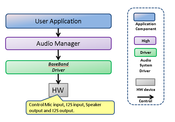
When Audio SubSystem operates in Through Mode, the User Application can set up data flow without CPU intervention.
I2S or MIC can be specified as the data input source. Speaker or I2S can be specified as the data output destination.
In addition, User Application can set two data flows. By using MIXER, you can mix two input data into one.
For setting to User Application, communicate command with Message. Message communication has an ID for each client. In the case of Audio Through, the ID is as follow:
User Application : MSGQ_AUD_APP Audio Manager : MSGQ_AUD_MNG
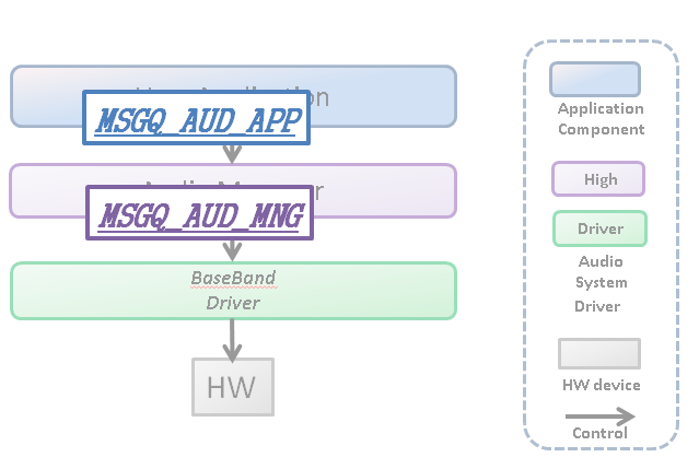
These IDs must be specified.
5.3.3.11.1. Audio HW internal dataflow
In the Audio Through, inside the Audio HW is the data flow shown in Audio HW internal dataflow.
There are I2S In, MIC In, Mixer Out as input sources of data flow.
There are Mixer In1, Mixer In2, I2SOut as output destinations of the data flow. When Mixer In1 or Mixer In2 is set as the output destination, it outputs from MixerOut to Speaker Out.
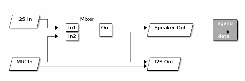
The relationship between configurable input source and output destination is as follow:
| Input source | Output destination |
|---|---|
I2S In |
Mixer In1, Mixer In2 |
MIC In |
Mixer In1, Mixer In2, I2S Out |
Mixer Out |
I2S Out |
5.3.3.11.2. How to use
"AudioManager" is a software component designed to control audio subsystem and support audio through.
Therefore, in order to support Audio Through, it is necessary to call the generation function of the following objects in advance.
When necessary objects are generated, initialization processing such as audio HW setting, power on, change of operation mode, etc. is performed in order to perform Audio Through operation.
This can be performed by issuing the following commands in the order below:
To turn on the audio block, issue the AUDCMD_POWERON, PowerOnParam command, also change the state of the Audio Sub system to the Ready state.
Enable_sound_effect must be fixed to AS_DISABLE_SOUNDEFFECT.
AudioCommand command;
command.header.packet_length = LENGTH_POWERON;
command.header.command_code  = AUDCMD_POWERON;
command.header.sub_code      = 0x00;
command.power_on_param.enable_sound_effect = AS_DISABLE_SOUNDEFFECT;
AS_SendAudioCommand(&command);After performing PowerOn and transitioning to the Ready state, use the AUDCMD_INITOUTPUTSELECT, InitOutputSelectParam command to select the output destination from Mixer.
The setting of output_device_sel is as follow:。
   AS_OUT_OFF: Output OFF
   AS_OUT_SP:  Output from Speaker
AS_OUT_I2S: Output from I2S| If you select AS_OUT_I2S to control the HW power supply, it will not use Speaker as output. If you want to use both I2S and Speaker with Audio Through, select AS_OUT_SP. |
  AudioCommand command;
  command.header.packet_length = LENGTH_INITOUTPUTSELECT;
  command.header.command_code  = AUDCMD_INITOUTPUTSELECT;
  command.header.sub_code      = 0x00;
  command.init_output_select_param.output_device_sel = AS_OUT_SP;
AS_SendAudioCommand(&command);AUDCMD_SETTHROUGHSTATUS The state of AudioSubSystem is transited to the Through state by the command.
-
Command setting example
  AudioCommand command;
  command.header.packet_length = LENGTH_SET_THROUGH_STATUS;
  command.header.command_code = AUDCMD_SETTHROUGHSTATUS;
  command.header.sub_code = 0x00;
AS_SendAudioCommand(&command);When setting Speaker as output, you can set the volume with AUDCMD_SETVOLUME, SetVolumeParam. The setting of each parameter is as follow:
Volume can not be changed in I2S.
Volume of MIXER 1. Set dB with a 10-fold integer value. The range can be set from -1020 (-102.0 dB) to 120 (+ 12.0 dB) with step size 5 (0.5 dB).
Volume of MIXER 2. The range is the same as input1_db.
The volume after mix of MIXER 1 and MIXER 2. The range is the same as input1_db.
  AudioCommand command;
  command.header.packet_length = LENGTH_SETVOLUME;
  command.header.command_code  = AUDCMD_SETVOLUME;
  command.header.sub_code      = 0;
  command.set_volume_param.input1_db = 0;    /* 0.0dB */
  command.set_volume_param.input2_db = 0;    /* 0.0dB */
  command.set_volume_param.master_db = -200; /* -20.0dB */
AS_SendAudioCommand(&command);Please refer to Recorder Init Mic Gain.
|
The microphone that can be used is a combination of CXD5247 analog microphone 1, CXD5247 analog microphone 2, CXD5247 digital microphone 1 or CXD5247 digital microphone 2 combination. You can change the microphone by changing the Layout, the same as Recorder Init Mic Gain. |
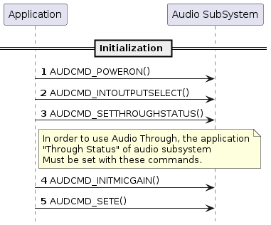
By setting the data flow path, data input / output is started.
You can set two data paths at the same time with AUDCMD_SETTHROUGHPATH, AsSetThroughPathParam, AsThroughPath. The setting of each parameter of each data path is as follow:
Enable / disable the data path.
true: Enabled
false: Disable
Set the data input source.
AS_THROUGH_PATH_IN_MIC : MIC As input source
AS_THROUGH_PATH_IN_I2S1 : I2SA s input source
AS_THROUGH_PATH_IN_MIXER : Mixer Out As input source
| MIC refers to CXD5247 analog microphone 1 and CXD5247 analog microphone 2 for analog microphone. In the case of a digital microphone, it refers to CXD5247 digital microphone 1 and CXD5247 digital microphone 2. I2S refers to I2S0. |
Set the data output destination.
AS_THROUGH_PATH_OUT_MIXER1 : Mixer In1 As output destination
AS_THROUGH_PATH_OUT_MIXER2 : Mixer In2 As output destination
AS_THROUGH_PATH_OUT_I2S1 : I2S As output destination
| I2S refers to I2S0 |
  AudioCommand command;
  command.header.packet_length = LENGTH_SET_THROUGH_PATH;
  command.header.command_code  = AUDCMD_SETTHROUGHPATH;
  command.header.sub_code      = 0x00;
  command.set_through_path.path1.en  = true; (1)
  command.set_through_path.path1.in  = AS_THROUGH_PATH_IN_MIC; (2)
  command.set_through_path.path1.out = AS_THROUGH_PATH_OUT_I2S1; (3)
  command.set_through_path.path2.en  = true; (4)
  command.set_through_path.path2.in  = AS_THROUGH_PATH_IN_I2S1;   (5)
  command.set_through_path.path2.out = AS_THROUGH_PATH_OUT_MIXER1; (6)
AS_SendAudioCommand(&command);| 1 | Activate the data path 1 setting |
| 2 | Data path 1 uses MIC In as the input source |
| 3 | Data path 1 uses I2S Out as the output destination |
| 4 | Activate the data path 2 setting |
| 5 | Data path 2 uses I2S In as the input source |
| 6 | Data path 2 uses Mixer In 1 as the output destination |
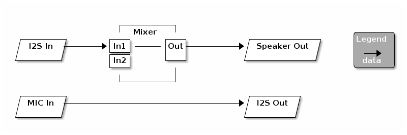
  AudioCommand command;
  command.header.packet_length = LENGTH_SET_THROUGH_PATH;
  command.header.command_code  = AUDCMD_SETTHROUGHPATH;
  command.header.sub_code      = 0x00;
  command.set_through_path.path1.en  = true; (1)
  command.set_through_path.path1.in  = AS_THROUGH_PATH_IN_MIC; (2)
  command.set_through_path.path1.out = AS_THROUGH_PATH_OUT_MIXER1; (3)
  command.set_through_path.path2.en  = true; (4)
  command.set_through_path.path2.in  = AS_THROUGH_PATH_IN_MIXER;  (5)
  command.set_through_path.path2.out = AS_THROUGH_PATH_OUT_I2S1; (6)
AS_SendAudioCommand(&command);| 1 | Activate the data path 1 setting |
| 2 | Data path 1 uses MIC In as the input source |
| 3 | Data path 1 uses Mixer In 2 as the output destination |
| 4 | Activate the data path 2 setting |
| 5 | Data path 2 uses Mixer Out as the input source |
| 6 | Data path 2 uses I2S Out as the output destination |
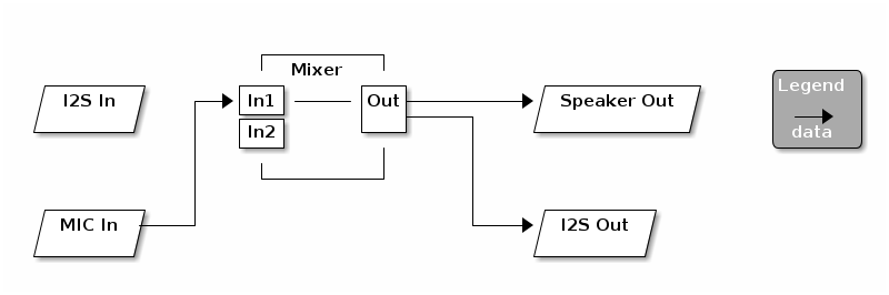
  AudioCommand command;
  command.header.packet_length = LENGTH_SET_THROUGH_PATH;
  command.header.command_code  = AUDCMD_SETTHROUGHPATH;
  command.header.sub_code      = 0x00;
  command.set_through_path.path1.en  = true; (1)
  command.set_through_path.path1.in  = AS_THROUGH_PATH_IN_MIC; (2)
  command.set_through_path.path1.out = AS_THROUGH_PATH_OUT_MIXER2; (3)
  command.set_through_path.path2.en  = false; (4)
AS_SendAudioCommand(&command);| 1 | Activate the data path 1 setting |
| 2 | Data path 1 uses MIC In as the input source |
| 3 | Data path 1 uses Mixer In 2 as the output destination |
| 4 | Invalidate the setting of data path 2 |
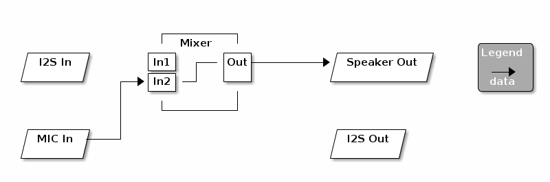
  AudioCommand command;
  AudioResult result;
  command.header.packet_length = LENGTH_SET_THROUGH_PATH;
  command.header.command_code  = AUDCMD_SETTHROUGHPATH;
  command.header.sub_code      = 0x00;
  command.set_through_path.path1.en  = true; (1)
  command.set_through_path.path1.in  = AS_THROUGH_PATH_IN_I2S1; (2)
  command.set_through_path.path1.out = AS_THROUGH_PATH_OUT_MIXER1; (3)
  command.set_through_path.path2.en  = true; (4)
  command.set_through_path.path2.in  = AS_THROUGH_PATH_IN_I2S1;  (5)
  command.set_through_path.path2.out = AS_THROUGH_PATH_OUT_MIXER2; (6)
  AS_SendAudioCommand(&command);

  AS_ReceiveAudioResult(&result); (7)

  command.header.packet_length = LENGTH_SET_THROUGH_PATH;
  command.header.command_code  = AUDCMD_SETTHROUGHPATH;
  command.header.sub_code      = 0x00;
  command.set_through_path.path1.en  = true;
  command.set_through_path.path1.in  = AS_THROUGH_PATH_IN_MIXER; (8)
  command.set_through_path.path1.out = AS_THROUGH_PATH_OUT_I2S1; (9)
  command.set_through_path.path2.en  = false;
AS_SendAudioCommand(&command);| 1 | Activate the data path 1 setting |
| 2 | Data path 1 uses I2S In as the input source |
| 3 | Data path 1 uses Mixer In 1 as the output destination |
| 4 | Activate the data path 2 setting |
| 5 | Data path 2 uses Mic In as the input source |
| 6 | Data path 2 uses Mixer In 1 as the output destination |
| 7 | Receive the result |
| 8 | Data path 1 uses Mixer Out as the input source |
| 9 | Data path 1 uses I2S Out as the output destination |
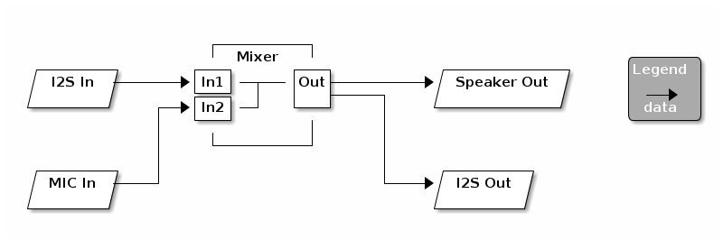
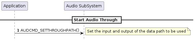
5.3.3.11.3. Build Configurations
To use the function of AudioThrough.
cd sdk
tools/config.py -m
With Config menu you need to configure the following.
Select options in below:
[Device Drivers]
  [Board specific drivers]
    [CXD56 Audio Driver]                   <= Y

[Application Configuration]
  [Spresense SDK]
    [SDK audio]                            <= Y
5.3.3.11.4. Error Attentions and Approach
A list of warnings when playing music and the corrective actions are as follow. See Error Information of Audio SubSystem for details.
| ID | Attention Code | Attention Level | Approach |
|---|---|---|---|
0x0F |
AS_ATTENTION_SUB_CODE_TASK_CREATE_ERROR |
ERROR |
This is due to insufficient heap space. Expand the heap area. |
|
AS_ATTENTION_SUB_CODE_SIMPLE_FIFO_UNDERFLOW
If this occurs, audio playback stops and playback errors will occur.
When this happens, immediately issue the AsStopPlayerParam command and change to the playback stop state. Be sure to clear FIFO after transition to play stop. If you do not noise will be generated. |
5.3.4. Object Level API
The Audio function APIs provide simpler functions than the High Level API.
You can create more flexible applications by using the Object Level API.
5.3.4.1. About Usecase
Below are some examples of use cases using the Object Level API.
5.3.4.1.1. Usecase 1
This is a case to decode sound output of Audio data using MediaPlayerObject and OutputMixerObject .
PCM data from MediaPlayerObject can be processed by Application and sent to OutputMixerObject .
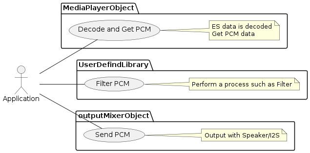
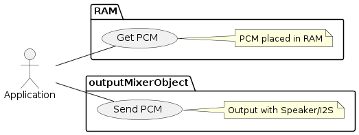
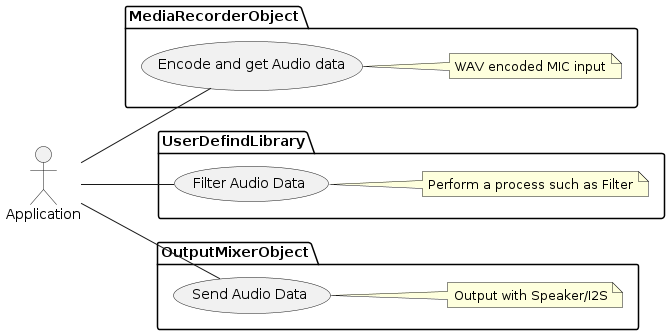
5.3.4.2. MediaPlayerObject
MediaPlayerObject performs decode management of the audio data and output of the decoding result PCM.
Two players can be used at the same time, and they are controlled individually by parameter of PlayerID in each API.
Application passes ES data to MediaplayerObject via a buffer called Simple FIFO.
If the buffer underflows, playback stops. Application design is required to prevent this condition occurring.
When decoding is completed, MediaPlayerObject notifies MemoryHandle of PCM data.
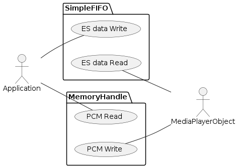
It is also possible to send PCM data to the OutputMixerObject . In this case there is no response to Application .
However, as a matter of course, it is necessary to generate and start OutputMixerObject .
(Default is a Callback response to Application as shown above.)
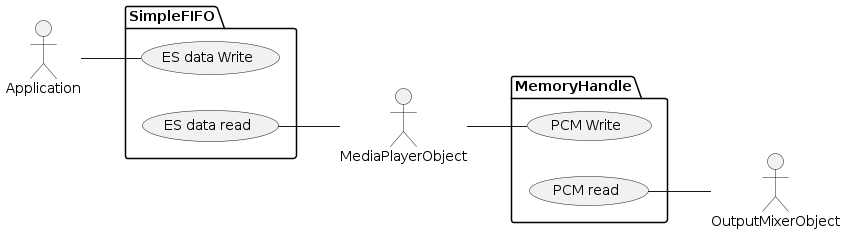
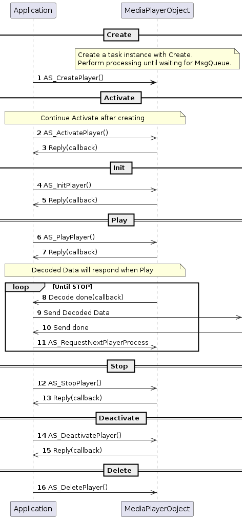
5.3.4.3. OutputMixerObject
OutputMixerObject manages sending PCM data (Rendering).
Application sends PCM data to OutputMixerObject via MemoryHandle.
When Rendering is completed, OutputMixerObject responds with a callback.
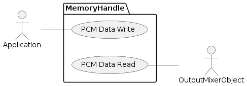
5.3.4.3.1. Functions
Send PCM data. When transmission is completed, the response is called back.
Please pass the following data before transmission of data passed in this API is completed.
If it not done in time, the DMA transfer underflows and stops.
Also, PCM data is actually sent when this API is called more than once.
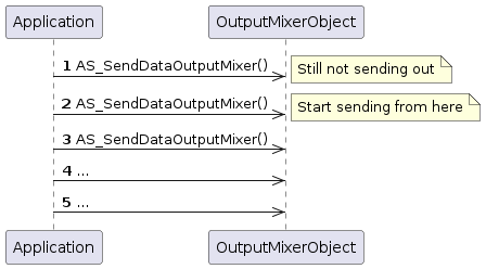
bool AS_SendDataOutputMixer(FAR AsSendDataOutputMixer &sendparam);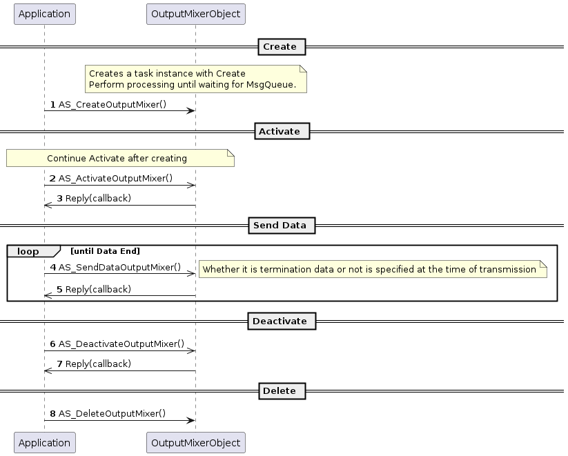
5.3.4.4. MediaRecorderObject
MediaRecorderObject manages the encoding of Audio data and outputs the encoding result ES.
It encodes the input (PCM data) from the captured MIC or IS 2 and sequentially stores it in the Simple FIFO buffer.
Application can extract ES data by reading the FIFO. The extraction must be done in time, since overwriting stops recording. The application needs to be designed to prevent this condition.
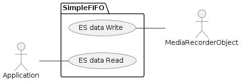
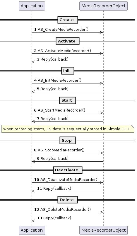
5.3.6. Preprocess and UserCustomDSP
Preprocess is a architecture which can apply user defined signal process to recording audio data. The signal process is done by UserCustomDSP. Here explains the detail of architecture.
5.3.6.1. Codes of framework
If you would like to add your signal process, you should create UserCustomDSP first. A minimum set of source code for UserCustomDSP is provided as framework by SDK. You should fetch them and build with your source code, and you can create UserCustomDSP.
| Pleaser refer Audio Recorder Tutorial for how to create UserCustomDSP. |
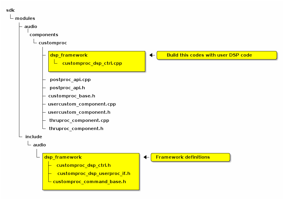
5.3.6.2. Relation between framework codes and user codes
Relation between framework codes and user codes should follow class diagram. You will edit "User Edit DSP Codes" inside diagram. (You don’t need to edit framework codes.)
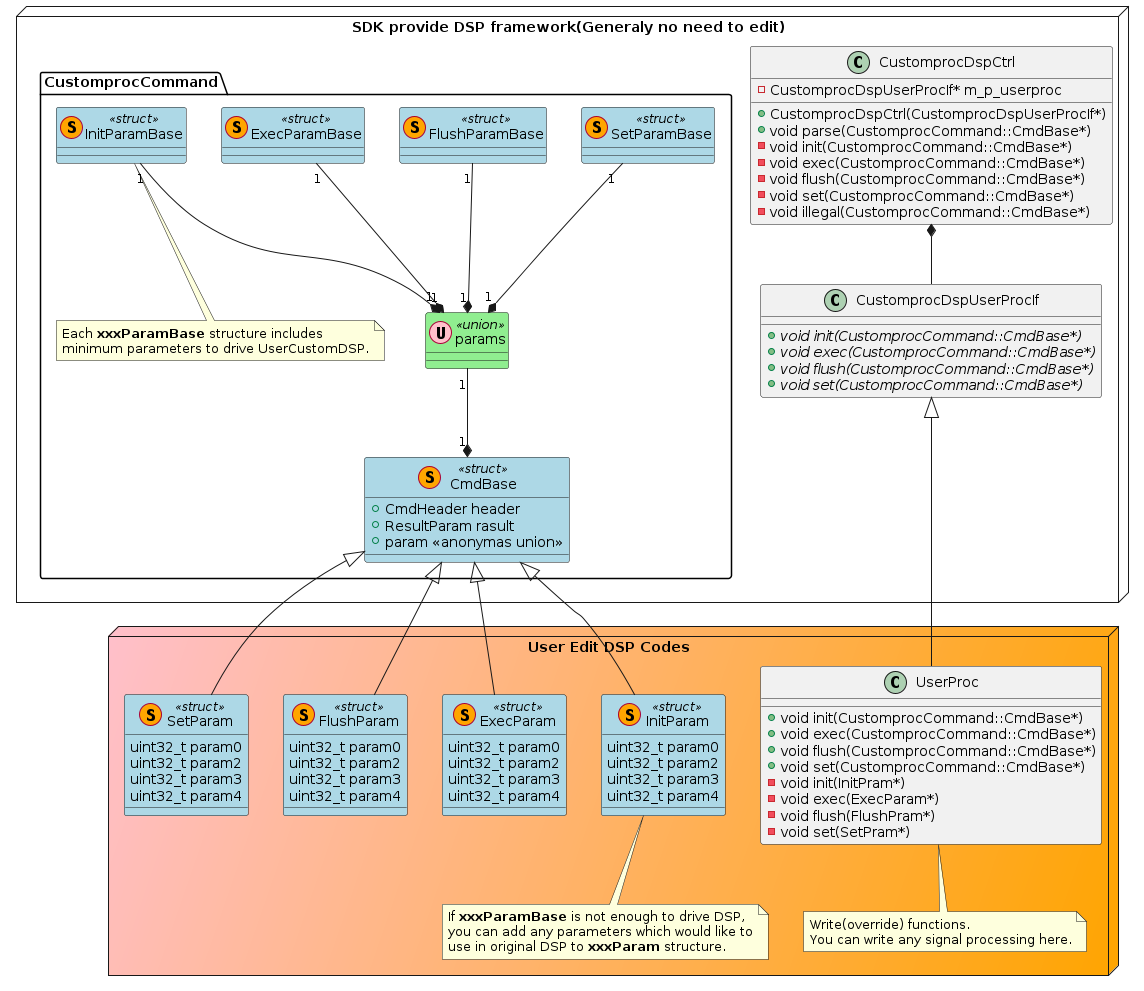
When you edit user codes, you should follow these points.
-
A Command format between UserCustomDSP and user codes are able to define freely, but it must inherit
CustomprocCommand::CmdBasewhich is defined in framework. Because, format must follow Command format.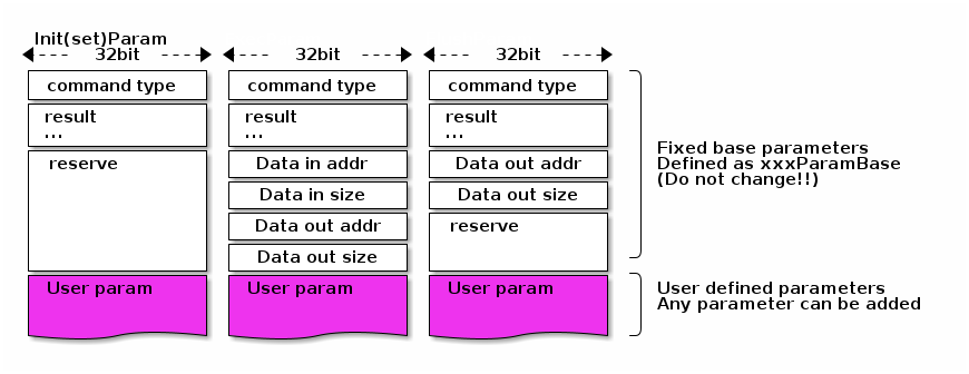 Figure 33. Command format between UserCustomDSP and user codes
For example, write as follow.
struct InitPram : public CustomprocCommand::CmdBase { uint8_t ch_num; ... } -
A class which you write user codes (
UserProcin Class Diagram) must inheritCustomprocDspUserProcIf(pure abstract class) of framework, and override the methods to implement.class UserProc : public CustomprocDspUserProcIf { void init(CustomprocCommand::CmdBase*); ... }
5.3.6.3. UserCustomDSP works
5.3.6.3.1. Internal State transition
UserCustomDSP have state transition like follow diagram. The trigger of transition will Init , Exec , Flush , Set command.
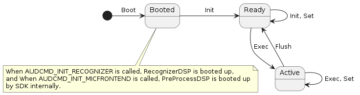
5.3.6.3.2. DSP Sequence
The UserCustomDSP which is created with framework codes runs as follow sequences.
Please refer to Init MicFrontend(Recorder) for role of UserCustomDSP in Audio Recorder, and Init MicFrontend(Recognizer) for Audio Recognizer.
As follow diagram, Init , Set commands are sent to UserCustomDSP when the user codes calls for API.
On the other hand, Exec , Flush commands are sent to UserCustomDSP by AudioSubsystem internally every time capture audio data.
(You don’t need to send Exec , Flush commands from user codes.)
Brief sequence.
-
AUDCMD_INIT_MICFRONTEND, Boot up DSP with indicated binary file.
-
AUDCMD_INIT_PREPROCESS_DSP,
Initis sent to UserCustomDSP. It will used to notify some parameters to init UserCustomDSP. For example, ch number, bit length, and more. -
AUDCMD_STARTREC, Start capturing audio data and send it to UserCustomDSP with
Exec. Apply signal process to them by UserCustomDSP. -
AUDCMD_SET_PREPROCESS_DSP,
Setis sent to UserCustomDSP. You can send anytime even if afterStartwas sent. For examples, set filter coefficient. -
AUDCMD_STOPREC, Stop capturing audio data and send
FlushafterExecof last frame.Flushis used for flush of delayed samples.
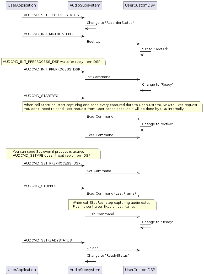
Brief sequence.
-
AUDCMD_INIT_RECOGNIZER, Boot up DSP with indicated binary file.
-
AUDCMD_INIT_RECOGNIZER_DSP,
Initis sent to UserCustomDSP. It will used to notify some parameters to init UserCustomDSP. For example, ch number, bit length, and more. -
AUDCMD_START_RECOGNIZER, Start capturing audio data and send it to UserCustomDSP with
Exec. Apply recognizing process to them by UserCustomDSP. -
AUDCMD_SET_RECOGNIZER_DSP,
Setis sent to UserCustomDSP. You can send anytime even if afterStartwas sent. For examples, recognition parameters. -
AUDCMD_STOP_RECOGNIZER, Stop capturing audio data and send
FlushafterExecof last frame.Flushis used for flush of delayed samples.
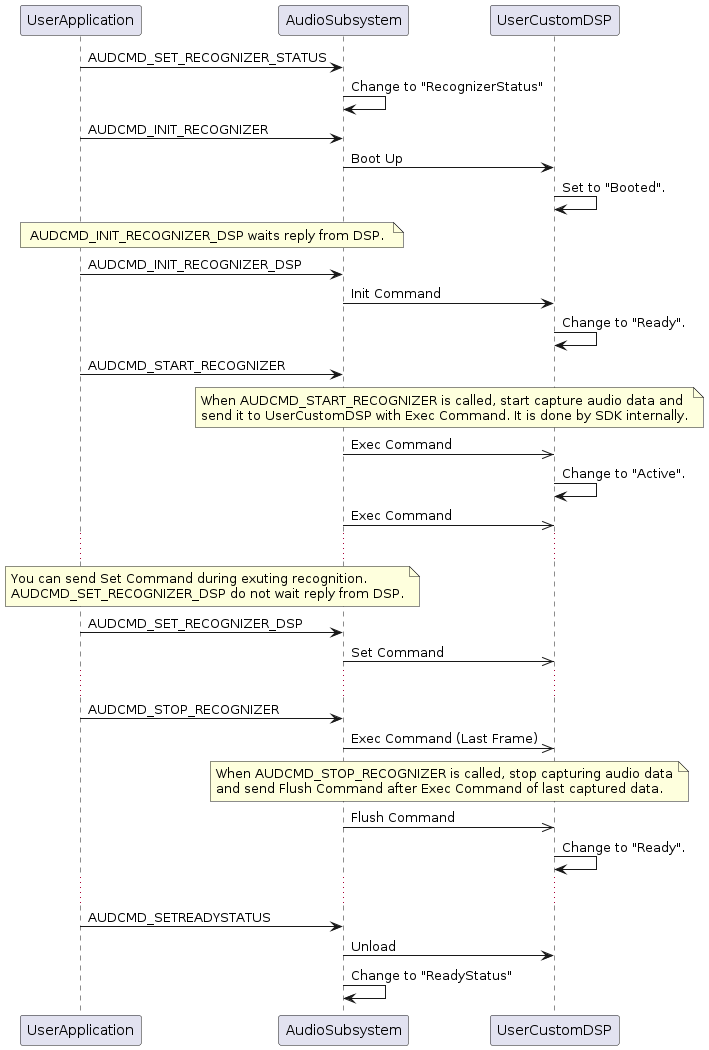
5.3.7. Error Information of Audio SubSystem
5.3.7.1. Overview
The High Level API of Audio SubSystem has an interface for the sending and receiving data for commands and results, and there are two kinds of errors.
If there is a problem with the command issued for SubSystem, "ErrorResponse" result is returned instead of completion response to command event. This error is called a response error.
Also, if an error occurs inside the system, an "ErrorAttention" event will be generated from inside the system and notified as a result. It is called an attention error.
To perform troubleshooting identify the error type as response error or attention error, and read the appropriate parts of the following sections.
5.3.7.2. Response Error
When you want to control the SubSystem, and there is a status violation or a parameter mistake, a response of the completion response to each command will not occur, and an "ErrorResponse" result will be generated as a response.
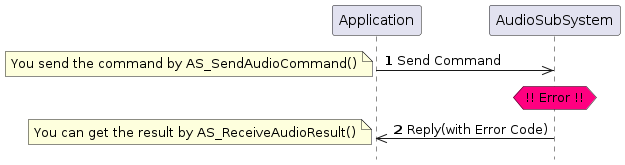
For the data format of the "ErrorResponse", see result format and ErrorResponse.
"Error Response" has a "Error Code", and "Error Code" means that what kind of error occurred.
The list of "Error Codes" is shown below.
| Error Code | Value | Description |
|---|---|---|
0x01 |
State violation |
|
0x02 |
Packet length mismatch |
|
0x03 |
Unknown command |
|
0x04 |
Invalid command |
|
0x05 |
Power ON failure |
|
0x06 |
Power OFF failure |
|
0x07 |
DSP startup failure |
|
0x08 |
DSP termination failure |
|
0x09 |
DSP version mismatch |
|
0x0A |
Input/output parameter error |
|
0x0B |
Data path clear failure |
|
0x0C |
Input/output is disabled |
|
0x0D |
Decoder DSP initialization failure |
|
0x0E |
Encoder DSP initialization failed |
|
0x0F |
Filter DSP initialization failed |
|
0x11 |
Incorrect codec type specification |
|
0x13 |
Wrong number of channels specified |
|
0x14 |
Incorrect sampling frequency |
|
0x15 |
Incorrect bit rate specification |
|
0x16 |
Incorrect bit length specification |
|
0x17 |
Incorrect compression ratio specification |
|
0x18 |
Incorrect specification of Player instance |
|
0x19 |
Incorrect input device specification |
|
0x1A |
Incorrect output device specification |
|
0x1B |
Incorrect input device handle specification |
|
0x28 |
Incorrect mute parameter specification |
|
0x2B |
I/O function initialization failure |
|
0x2C |
Input data acquisition failure |
|
0x2E |
Memory pool setting failure |
|
0x2F |
Simple FIFO data is exhausted |
|
0x30 |
Incorrect microphone gain specification |
|
0x32 |
Incorrect output destination setting |
|
0x33 |
Incorrect clear stereo setting |
|
0x34 |
Incorrect volume specification |
|
0x35 |
Incorrect mute target specification |
|
0x36 |
Incorrect beep parameter specification |
|
0x37 |
Data queue management failure |
|
0x39 |
Incorrect clock operation mode specification |
|
0x3A |
Clock operation mode setting failure |
|
0x3B |
Incorrect speaker drive capability setting |
|
0x3D |
Incorrect microphone setting |
|
0x3E |
Used without generating the Object layer module |
Please refer to here for details of "Error Code".
5.3.7.3. Attention Error
An "ErrorAttention" result is generated for errors while processing inside the Audio Sub System (not command processing). In order to receive this event, it is necessary to register the callback function with the AS_CreateAudioManager.
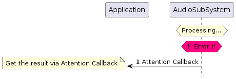
For the data format of the "ErrorAttention" result, see Result format and Error Attention
This error is caused by a control failure such as the supply of ES(Elementary Stream) being interrupted at the time of rendering operation, the ES write buffer overflowing at the time of recording operation, a system error such as depletion of memory resources, delay of real time processing, etc. These are fatal errors, so please implement error handling based on the type of error that occurred.
Also, by changing the program implementation, errors should be reduced or eliminated.
The list of "Error Codes" on "ErrorAttention" is shown below.
| Attention Code | Value | Description |
|---|---|---|
0x01 |
DMA transfer underflow |
|
0x02 |
DMA transfer overflow |
|
0x03 |
DMA transfer failure |
|
0x05 |
Underflow of SimpleFIFO |
|
0x06 |
Overflow of SimpleFIFO |
|
0x07 |
Illegal event reception |
|
0x08 |
Internal status error |
|
0x09 |
Internal parameter error |
|
0x0A |
Pop error for internal queue |
|
0x0B |
Push error for internal queue |
|
0x0C |
Internal queue exhaustion |
|
0x0D |
Memory handle acquisition failure |
|
0x0E |
Memory handle release failure |
|
0x0F |
Task creation failure |
|
0x10 |
Failure to create or delete an instance |
|
0x12 |
DSP startup failure |
|
0x13 |
DSP termination failure |
|
0x14 |
Error in DSP processing |
|
0x16 |
Invalid data received from DSP |
|
0x18 |
DSP version mismatch |
|
0x19 |
Error in audio driver |
|
0x1A |
ES data analysis error |
|
0x1E |
Acquisition failure of DSP log buffer |
|
0x1F |
Fatal error in DSP processing |
|
0x20 |
Command transmission error to DSP |
Please refer to here for details of "Attention Code".
A level of importance is specified for the attention notification, and the processing method for recovery is dependent on the severity of the error.
| Level | value | Description |
|---|---|---|
FATAL |
0x03 |
A system call error, etc. that is not recoverable and requires a reset to restore. |
ERROR |
0x02 |
It is an error in the operation of which the audio system can not continued with the internal error (queue Full / Empty, DSP load / unload etc). It is possible to recover by returning the system to the initial state (Ready state). |
WARN |
0x01 |
There is a possibility that the operation is abnormal, such as encode / decode error, data underflow / overflow, etc. There is a possibility that abnormality has occurred in voice data, etc., but operation can continue. |
5.3.7.4. Error Code List
Below is a list of "Error Code" added to "Error Response".
5.3.7.4.32. AS_ECODE_SIMPLE_FIFO_UNDERFLOW
- code
-
0x2F
- description
-
At the start of Audio playback, the Simple FIFO used as the ES buffer underflows.
When starting playback, AudioSubSystem immediately extracts ES data from SimpleFIFO and starts decoding. So in the application, it is necessary to put ES data in the FIFO before playback starts.
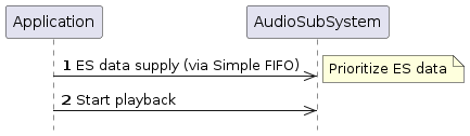
5.3.7.6. Module ID List
AudioSubSystem ID list of modules to be used internally.
It is notified with Attention callback along with attention code, and it judges which module caused an error.
| Module ID | Value | Description |
|---|---|---|
AS_MODULE_ID_AUDIO_MANAGER |
0 |
Audio Manager |
AS_MODULE_ID_AUDIO_DRIVER |
1 |
Audio Baseband Driver |
AS_MODULE_ID_MIC_FRONTEND_OBJ |
2 |
FrontEnd Object |
AS_MODULE_ID_INPUT_DATA_MNG_OBJ |
3 |
Input Data Manager Object |
AS_MODULE_ID_MEDIA_RECORDER_OBJ |
4 |
Media Recorder Object |
AS_MODULE_ID_OUTPUT_MIX_OBJ |
5 |
Output Mix Object |
AS_MODULE_ID_PLAYER_OBJ |
6 |
Player Object |
AS_MODULE_ID_RECOGNITION_OBJ |
7 |
Recognition Object |
AS_MODULE_ID_SOUND_EFFECT_OBJ |
8 |
Sound Effect Object |
AS_MODULE_ID_SYNTHESIZER_OBJ |
9 |
Synthesizer Object |
AS_MODULE_ID_CAPTURE_CMP |
10 |
Capture Component |
AS_MODULE_ID_DECODER_CMP |
11 |
Decoder Component |
AS_MODULE_ID_ENCODER_CMP |
12 |
Encoder Component |
AS_MODULE_ID_FILTER_CMP |
13 |
Filter Component |
AS_MODULE_ID_RECOGNITION_CMP |
14 |
Recognition Component |
AS_MODULE_ID_RENDERER_CMP |
15 |
Renderer Component |
AS_MODULE_ID_POSTPROC_CMP |
16 |
Postfilter Component |
AS_MODULE_ID_OSCILLATOR_CMP |
17 |
Oscillator Component |
AS_MODULE_ID_CUSTOM_CMP |
18 |
Custom Component |
5.4. Camera
5.4.1. Overview
CXD5602 has the 8-bit parallel Camera I/F, and can be connected to Camera module with such I/F. Currently, Spresense support Camera module which mount Sony ISX012 or Sony ISX019. Camera module has the I/F for module control in addition to I/F for data. I/Fs for ISX012’s control and ISX019’s control are I2C.
HW overview is as follow:
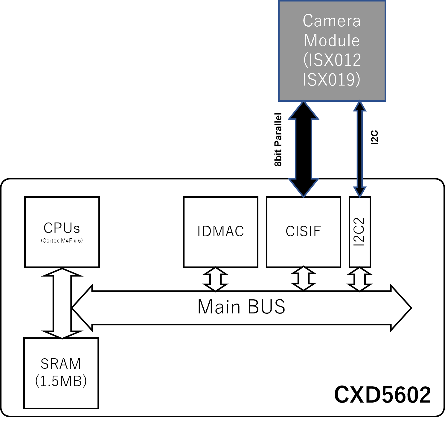
CISIF, which is Camera I/F block in CXD5602, bridges 8-bit parallel I/F and internal bus of CXD5602. In addition, ISX012 camera module use I2C bus.
This chapter provides an overview of how to control camera module connected to this Camera I/F by Spresense SDK.
Camera driver I/F of Spresense SDK is similar to V4L2 which is well-known on Linux systems. Therefore, V4L2 application code is reusable easily. This I/F is called V4S(Video for Spresense).
V4S provides abstract APIs of camera functions by using standard file system interface(open, close and ioctl, ..). These APIs enable application not to care about camera device.
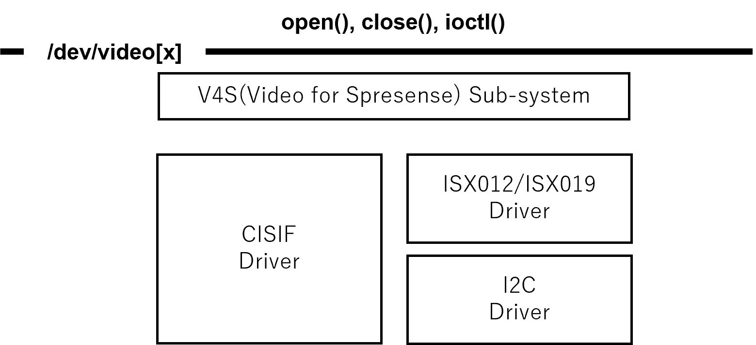
V4S provides two virtual streams. One is video stream for Camera preview. The other is still picture stream.
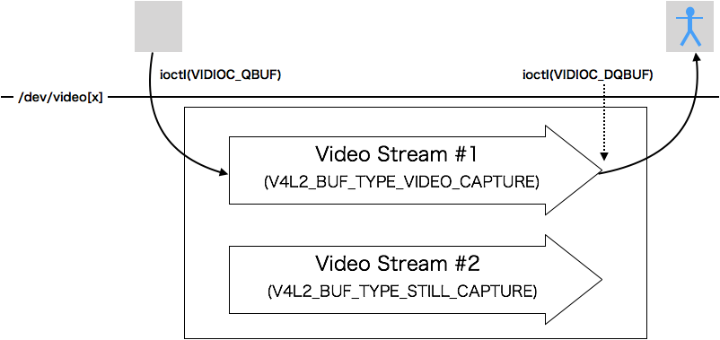
Application can get image data for each streams according to the following procedure:
-
prepare a buffer.
-
Enqueue the buffer to the driver’s queue by VIDIOC_QBUF.
-
Dequeue the buffer from the driver’s queue by VIDIOC_DQBUF.
|
The buffer need to be aligned on 32-bit boundary. |
Control stream is specified by v4l2_buf_type:
-
V4L2_BUF_TYPE_VIDEO_CAPTURE : stream for video image
-
V4L2_BUF_TYPE_STILL_CAPTURE : stream for still image
|
This V4L2_BUF_TYPE_STILL_CAPTURE is V4S-specific parameter. |
The outline from V4S initialization to image data capture is as follow:
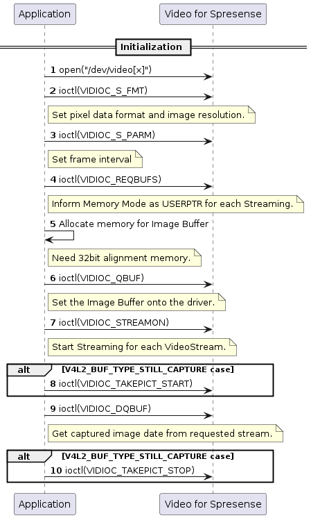
5.4.2. State Transition
Because V4S manages the states for each streams, application controls each streams in parallel.
About getting image from camera device, V4L2_BUF_TYPE_STILL_CAPTURE control has priority, that is, V4L2_BUF_TYPE_VIDEO_CAPTURE stream stop getting image from VIDIOC_TAKEPICT_START to VIDIOC_TAKEPICT_STOP.
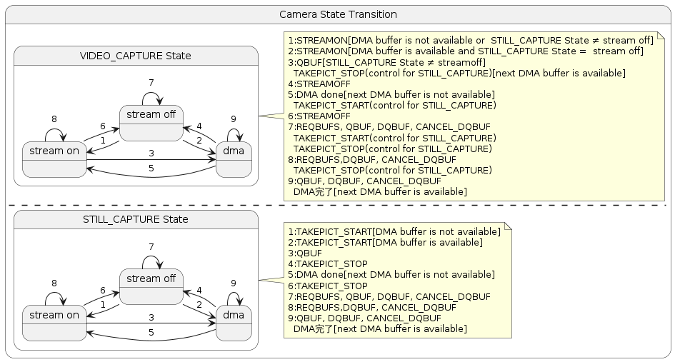
5.4.3. V4S supported ioctl command
| class | command | purpose | Spresense-specific .1+ | Capability acquisition |
|---|---|---|---|---|
Get information about connected devices. |
Support only the member |
Buffer Control |
||
Initialize buffer control field in driver. |
Add parameter v4l2_buf_mode mode to give ring structure to buffers. |
Enqueue buffer which application prepared. |
||
V4L2 compliance |
Dequeue buffer which has image data. |
V4L2 compliance |
||
Cancel VIDIOC_DQBUF. |
Spresense-specific command |
Stream Control |
||
Start stream. |
V4L2 compliance |
|||
Stop stream. |
V4L2 compliance |
Start taking still pictures. |
||
Spresense-specific command |
Stop taking still pictures. |
Spresense-specific command |
||
Check range of frame setting |
Check pixel format and image size passed from application are valid |
V4L2 compliance |
Change frame setting |
|
Set pixel format and image size. |
V4L2 compliance |
|||
Set the frame interval. (Set the value in seconds in the form of a fraction. Fractions are set by integers that mean the denominator and numerator, respectively.) |
V4L2 compliance |
Get the frame interval. (Get the value in seconds in the form of a fraction. Fractions are represented by integers that mean the denominator and numerator, respectively.) |
||
|
V4L2 compliant .2+ |
Change clip area |
Set the coordinates from the upper left corner of the clip area and size. |
V4L2 compliant |
|
Get the coordinates from the upper left corner of the set clip area and size. |
V4L2 compliant |
Check range of camera setting |
||
Check range of camera setting. |
V4L2 compliance |
Check range of camera setting. This is the extended API of VIDIOC_QUERYCTRL and encompass VIDIOC_QUERYCTRL. |
||
V4L2 compliance |
About the camera setting items which take discrete values, get the discrete values. |
V4L2 compliance |
||
Get current value of camera setting |
Get current value of camera setting. |
V4L2 compliance |
||
Get current value of camera setting. This is the extended API of VIDIOC_G_CTRL and encompass VIDIOC_G_CTRL. |
V4L2 compliance |
Change camera setting |
||
Change camera setting |
V4L2 compliance |
Change camera setting This is the extended API of VIDIOC_S_CTRL and encompass VIDIOC_S_CTRL. |
||
V4L2 compliance |
Do camera setting when shutter button is half-pushed. |
Spresense-specific command |
5.4.4. Spresense Proprietary Specifications
5.4.4.1. The control type obtained by ioctl(VIDIOC_QUERYCTRL) and ioctl(VIDIOC_QUERY_EXT_CTRL)
The control type obtained by ioctl(VIDIOC_QUERYCTRL) and ioctl(VIDIOC_QUERY_EXT_CTRL) differ from V4L2 in certain parameters.
V4L2_CTRL_TYPE_MENU(the menu constructed by string) in V4L2, V4L2_CTRL_TYPE_INTEGER_MENU(the menu constructed by integer) in SPRESENSE.
-
V4L2_CID_COLORFX
-
V4L2_CID_EXPOSURE_AUTO
-
V4L2_CID_AUTO_N_PRESET_WHITE_BALANCE
-
V4L2_CID_ISO_SENSITIVITY_AUTO
-
V4L2_CID_EXPOSURE_METERING
-
V4L2_CID_SCENE_MODE
V4L2_CTRL_TYPE_BOOLEAN(false/true binary) in V4L2, V4L2_CTRL_TYPE_INTEGER(0(OFF),1(ON),2(AUTO switch) tri-valued) in SPRESENSE.
-
V4L2_CID_WIDE_DYNAMIC_RANGE
5.4.4.2. JPEG + YUV4:2:2 format
Application can get image data of a frame both with JPEG format and with YUV422 format by setting ioctl(VIDIOC_S_FMT) as follow:
For example, application can take a picture and display it without JPEG decoder.
| YUV422 data obtained using this feature can be converted to RGB565 format using the imageproc_convert_yuv2rgb() API. |
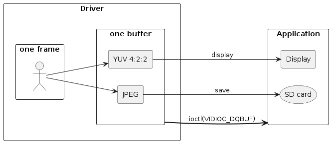
5.4.4.2.1. How to use JPEG + YUV422 format
Normally, VIDIOC_S_FMT is executed once to set width, height and pixel format. If you use this format, do it twice in total.
For the member type of the parameter structure struct v4l2_format, set the stream V4L2_BUF_TYPE_VIDEO_CAPTURE or V4L2_BUF_TYPE_STILL_CAPTURE for which you want to set this format with the same settings for the first and second times. For member fmt.pix, set JPEG for the first time and YUV422 for the second time according to the following.
| Time | pixelformat | width | height |
|---|---|---|---|
1st time |
V4L2_PIX_FMT_JPEG_WITH_SUBIMG |
JPEG width |
JPEG height |
2nd time |
V4L2_PIX_FMT_SUBIMG_UYVY |
YUV422 width |
YUV422 height |
For the second pixelformat, it is necessary to specify the definition with SUBIMG. For example, if V4L2_PIX_FMT_UYVY is set, the simple YUV422 format will be set.
For available settings, refer to Settings available in ISX012 or Settings available in ISX019, depending on the device used.
5.4.4.3. API for 3A adjustment time saving just after power-on
You can save time until 3A adjustment complete by using V4L2_CID_3A_PARAMETER in ioctl(VIDIOC_S_EXT_CTRLS) and ioctl(VIDIOC_G_EXT_CTRLS). Also, you can check whether 3A adjustment status completed or not by V4L2_CID_3A_STATUS.
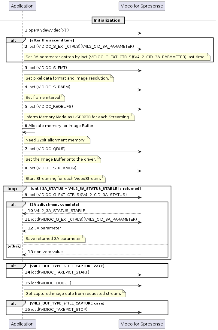
5.4.4.3.1. Get and change initial value of 3A adjustment parameter
You can get 3A adjustment parameter and change initial value of 3A adjustment parameter by executing ioctl(VIDIOC_G_EXT_CTRLS) and ioctl(VIDIOC_S_EXT_CTRLS) with the following settings.
-
ctrl_class: Set V4L2_CTRL_CLASS_CAMERA. -
control→id: Set V4L2_CID_3A_PARAMETER. -
control→p_u16: Define a uint16 type array entity with 3 elements and set the address to the entity.
In ioctl(VIDIOC_G_EXT_CTRLS) case, 3A adjustment parameter is set to the address pointed to by control→p_u16 .
In ioctl(VIDIOC_S_EXT_CTRLS) case, you can change initial value of 3A adjustment parameter by setting value to the address pointed to by control→p_u16 .
5.4.4.3.2. Get 3A adjustment status
You can get 3A adjustment status by executing ioctl(VIDIOC_G_EXT_CTRLS) with the following settings.
-
ctrl_class: Set V4L2_CTRL_CLASS_CAMERA. -
control→id: Set V4L2_CID_3A_STATUS.
If 3A adjustment completes, control→value = V4L2_3A_STATUS_STABLE.
Otherwise, adjustment operating bits(V4L2_3A_STATUS_AE_OPERATING and/or V4L2_3A_STATUS_AWB_OPERATING) are on.
5.4.5. Restrictions of image size and frame rate
5.4.5.1. Settings available in ISX012
Valid image size in VIDIOC_S_FMT and valid frame interval(reciprocal number of frame rate) in VIDIOC_S_PARM are related to each other. For example, when using larger image size, frame interval must be larger(frame rate must be smaller).
Supported ranges in Spresense + ISX012 environment are as follow:
ISX012 supported frame rates are 120 / 60 / 30 / 15 / 7.5 / 6 / 5. In the following diagram of YUV4:2:2 format case,
-
≦ QVGA : application use all of 120FPS to 5FPS, because max FPS=120.
-
> QVGA : application use 60FPS to 5FPS(can not use 120FPS), because max FPS=60.
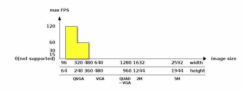
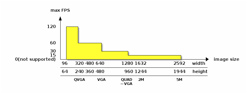
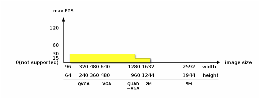
In JPEG + YUV4:2:2 format, YUV4:2:2 image size must be 96x64 to WQVGA(400x240). In this range, the above frame rate restriction is not affected.
5.4.5.2. Settings available in ISX019
With ISX019, regardless of the data format and frame size
30FPS, 15FPS, 10FPS, 7.5FPS are available.
FPS settings are set in the form of frame intervals using each member of the parm.capture.timeperframe of the ioctl (VIDIOC_S_PARM).
Setting the frame spacing available in .ISX019
| FPS | numerator | denominator |
|---|---|---|
30 |
1 |
30 |
15 |
1 |
15 |
10 |
1 |
10 |
7.5 |
2 |
15 |
Depending on the format, the frame size can only be set to a specific size.
Frame sizes available for .ISX019
| 1st ioctl(VIDIOC_S_FMT) | 2nd ioctl(VIDIOC_S_FMT) | ||||
|---|---|---|---|---|---|
pixelformat |
width |
height |
pixelformat |
width |
height |
V4L2_PIX_FMT_JPEG |
1280 |
960 |
- |
- |
- |
1280 |
720 |
||||
640 |
480 |
||||
640 |
360 |
||||
320 |
240 |
||||
160 |
120 |
||||
|
V4L2_PIX_FMT_RGB565 V4L2_PIX_FMT_UYVY |
320 |
240 |
- |
- |
- |
160 |
120 |
||||
V4L2_PIX_FMT_JPEG_WITH_SUBIMG |
1280 |
960 |
V4L2_PIX_FMT_SUBIMG_UYVY |
320 |
240 |
160 |
120 |
||||
1280 |
720 |
V4L2_PIX_FMT_SUBIMG_UYVY |
320 |
180 |
|
160 |
90 |
||||
640 |
480 |
V4L2_PIX_FMT_SUBIMG_UYVY |
320 |
240 |
|
160 |
120 |
||||
640 |
360 |
V4L2_PIX_FMT_SUBIMG_UYVY |
320 |
180 |
|
160 |
90 |
||||
320 |
240 |
V4L2_PIX_FMT_SUBIMG_UYVY |
320 |
240 |
|
160 |
120 |
||||
160 |
120 |
V4L2_PIX_FMT_SUBIMG_UYVY |
160 |
120 |
|
5.4.6. Restrictions of ioctl() timing
5.4.6.1. The timing which VIDIOC_S_FMT setting is not reflected correctly
Application can control V4L2_BUF_TYPE_VIDEO_CAPTURE and V4L2_BUF_TYPE_STILL_CAPTURE concurrently. But, in the "NG" timing of the following figure, VIDIOC_S_FMT(V4L2_BUF_TYPE_STILL_CAPTURE) setting may not be reflected correctly. (No problems in the single stream case or in the "OK" timing of the following figure.)
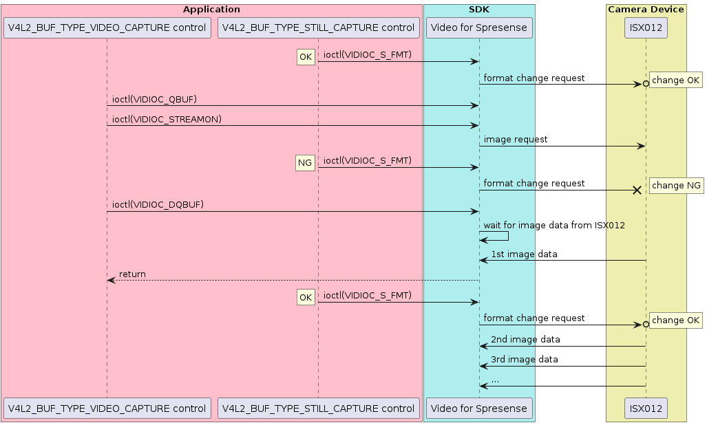
5.5. DNN Runtime
5.5.1. DNN Runtime Overview
The DNN Runtime library can perform recognition processing using the Deep Neural Network (DNN) using trained models by Neural Network Libraries or Neural Network Console provided by Sony.
User must create the trained model file (nnb file format) by Neural Network Console. See Preparation of a trained model to create it.
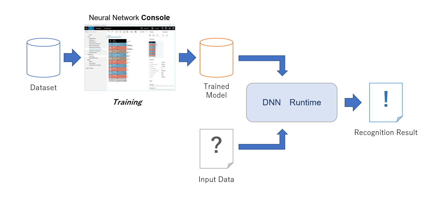
See Neural Network Libraries and Neural Network Console Official sites
And DNN Runtime Library uses NNabla C Runtime.
5.5.2. Sample code
This sample code is handwritten number recognition using the trained model file created at Preparation of a trained model section, and it was created from image_recognition.MNIST.LeNet sample network model.
The trained model created by image_recognition.MNIST.LeNet takes one image of 28 x 28 size and outputs 10 arrays. These 10 arrays correspond to the numbers recognized by the index, and the probability of each number is output in the array. For example, at the head of an array (index 0), the probability that the input image is the number "0" is output.
See DNNRT example README for more details.
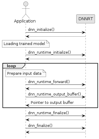
5.6. GNSS
The Spresense board has a Global Navigation Satellite System (GNSS) receiver that calculates its current position, velocity and time. To use this feature, you need to connect the GNSS chip to an antenna, such as the one on the Spresense Main Board.
5.6.1. Key Features
The embedded GNSS receiver on the Spresense board supports:
-
The GPS, GLONASS, BeiDou, Galileo and QZSS(Michibiki) GNSS systems.
-
The satellite-based augmentation systems (SBAS) capabilities of each GNSS systems.
-
Asynchronous position processing and notification.
-
Geo-fencing (detecting whether the receiver is leaving a specified area).
Your application can control these features using POSIX file functions such as open, close, read, seek, and ioctl. For example, the application can open the GNSS device file '/dev/gps', call the ioctl command, and use the read function to retrieve position data.
GNSS has several ioctl commands, which are described in this section.
-
For NuttX,
ioctlcommands have three arguments. -
For GNSS, the second parameter, "req", is a GNSS command, and the third parameter, "arg", is input/output data.
5.6.2. GNSS Configuration
To use the GNSS receiver, enable the device by setting CONFIG_CXD56_GNSS to Y.
[System Type]
[CXD56xx Package Configuration]
[GNSS device] (CXD56_GNSS) = Y
To enable conversion of the GPS position data to the widely-used NMEA data format, enable the NMEA conversion library /ref gnss_utilities_nmea, by setting CONFIG_CXD56_GNSS, CONFIG_LIBM, and CONFIG_GPSUTILS_CXD56NMEA_LIB to Y.
[System Type]
[CXD56xx Package Configuration]
[GNSS device] (CXD56_GNSS) = Y
[Application Configuration]
[Spresense SDK]
[Sensing]
[Support CXD56xx gnss NMEA convert library] (GPSUTILS_CXD56NMEA_LIB) = Y
If GPS signals are not available (e.g., at many indoor locations), you can use example GPS position data for test and development purposes.
To enable the example GPS position data, set CONFIG_CXD56_GNSS and CONFIG_EXAMPLES_GNSS for the GNSS position example.
[System Type]
[CXD56xx Package Configuration]
[GNSS device] (CXD56_GNSS) = Y
[Application Configuration]
[Spresense SDK]
[Examples]
[GNSS positioning example] (EXAMPLES_GNSS) = Y
If GPS signals are not available (e.g., at many indoor locations), you can use example the GNSS command emulator for test and development purposes.
To use this capability, enable the GNSS receiver and NMEA conversion library, as shown previously. Also enable CONFIG_EXAMPLES_GNSS_ATCMD for the GNSS command emulator example.
[System Type]
[CXD56xx Package Configuration]
[GNSS device] (CXD56_GNSS) = Y
[Device Drivers]
[USB Device Driver Support]
[USB Modem (CDC/ACM) support] = Y
[Application Configuration]
[Spresense SDK]
[Sensing]
[Support CXD56xx gnss NMEA convert library] (GPSUTILS_CXD56NMEA_LIB) = Y
[Application Configuration]
[Spresense SDK]
[Examples]
[GNSS CXD5603 @command emulator example] (EXAMPLES_GNSS_ATCMD) = Y
To test the GNSS receiver hardware, you can perform a factory test.
To enable a factory test:
-
Use
CONFIG_CXD56_GNSSto enable the GNSS receiver. -
Enable
CONFIG_EXAMPLES_GNSS_FACTORYfor the GNSS factory test example data. -
Select the
EXAMPLES_GNSS_FACTORY_SVIDaccording to the test environment.
To start a factory test, set [Application entry point] to gnss_factory_test.
To interpret the test results, multiply the values of cn and doppler results by 1000000.
[System Type]
[CXD56xx Package Configuration]
[GNSS device] (CXD56_GNSS) = Y
[Application Configuration]
[Spresense SDK]
[Examples]
[GNSS FACTORY test] (EXAMPLES_GNSS_FACTORY) = Y
[FACTORY TEST svid] (EXAMPLES_GNSS_FACTORY_SVID) = 1
[RTOS Features]
[Tasks and Scheduling]
[Application entry point]
set 'gnss_factory_test'
| To display the GNSS status on an E-ink display, see the following example code:spresense/examples/gnss_factory/README.txt |
You can configure the following settings:
-
The
GNSS backup file nameandGNSS CEP file nameto specify the binary files the GNSS uses to back up data and calculate circular error probable (CEP). Change the file name according to the file system the SDK uses.
[System Type]
[CXD56xx Package Configuration]
[GNSS setting]
[GNSS backup file name] = '/mnt/spif/gnss_backup.bin'
[GNSS CEP file name] = '/mnt/sd0/gnss_cep.bin'
The GNSS device driver notifies the application using POSIX’s poll or signal mechanism every time the receiver outputs position data. You can independently configure the maximum number of poll waits and signal receivers as shown below. The default values are 4 for poll and 4 for signal. For details, see Position Calculation Notification.
[System Type]
[CXD56xx Package Configuration]
[GNSS setting]
[GNSS max poll waiters] = 4
[GNSS max signal receivers] = 4
5.6.3. Device Control
This section describes the control commands for GNSS positioning.
The ioctl commands that control GNSS are listed in ioctl commands. Multiple applications can simultaneously open a GNSS device as a file. The GNSS device processes ioctl commands in the order it receives them. GNSS should arbitrate the commands issued from multiple applications. Otherwise, GNSS might run with unintended settings.
5.6.3.1. Startup
At startup, select the type of satellite used for positioning by calling CXD56_GNSS_IOCTL_SELECT_SATELLITE_SYSTEM. Set the positioning cycle by calling CXD56_GNSS_IOCTL_SET_OPE_MODE.
When performing a hot start, specify the current position and time. See Using GNSS Backup Data for information on configuring warm start and hot start.
5.6.3.2. Start Positioning
You can specify the start mode by calling CXD56_GNSS_IOCTL_START. The following table describes the start modes.
| These values are general reference values. They do not guarantee performance. |
| Start mode | IOCTL command parameter | TTFF (*1) | Information to use |
|---|---|---|---|
Cold Start |
> 45 sec |
Discard all current position, time, and satellite orbital information. Start positioning from the beginning. |
|
Warm Start |
> 20 sec |
Use the current position, time, and almanac. Do not use ephemeris. |
|
Hot Start |
>= 1 sec |
Use the current position, time, almanac, and ephemeris. |
(*1) Time To First Fix
If the data required for a “warm start” or “hot start” are not available, or it is a long time has passed since the last operation, the GNSS begins a “cold start”. “Cold start” will use the position data that is available.
5.6.3.3. Stop Positioning
To stop positioning, call CXD56_GNSS_IOCTL_STOP. It takes 200 to 300 milliseconds to stop the positioning.
5.6.3.4. Position Calculation Notification
There are two types of notifications:
-
Poll method
-
Signal method
To make the application poll the GNSS for its calculated position, use CONFIG_CXD56_GNSS_NPOLLWAITERS to set the number of tasks that must elapse before sending each poll request to the GNSS.
To have the GNSS signal its position to the application, call the ioctl command CXD56_GNSS_IOCTL_SIGNAL_SET with the data cxd56_gnss_signal_setting_s set to GNSS device descriptor for fd, 1 for enable, to any signal number for signo and to CXD56_GNSS_SIG_GNSS for gnsssig. Use this command to specify which signal the GNSS issues on each event, such as positioning. The application can make it wait with sigwaitinfo. If it is not necessary to receive a signal, set the enable param to 0 and call the ioctl command CXD56_GNSS_IOCTL_SIGNAL_SET. Your application can receive signals with a specified number of tasks by setting the configuration value CONFIG_CXD56_GNSS_NSIGNALRECEIVERS.
The application example program shows how to switch the notification method with CONFIG_EXAMPLES_GNSS_USE_SIGNAL.
5.6.4. Faster Positioning
This section explains how to use backup data and other information to fix the position quickly using hot start mode.
The diagram below shows the standard hot start flow to issue ioctl commands.
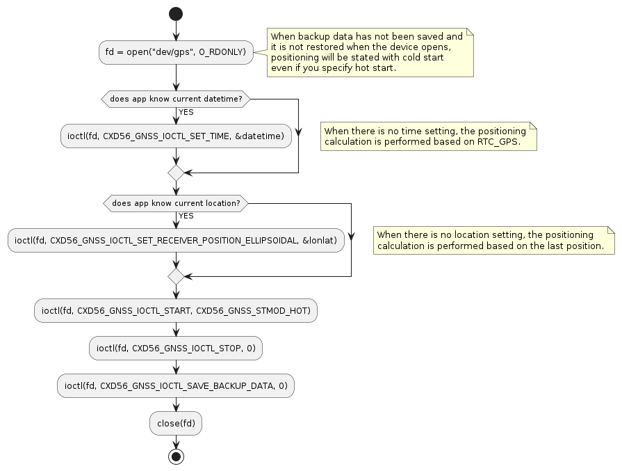
5.6.4.1. Using GNSS Backup Data
The receiver position, ephemeris, almanac, TCXO offset, and other information required for a hot start are included in the backup data. Also, using ioctl commands, you can save this backup data to a file on flash memory or other file system. When the backup data is saved, it is restored to RAM when the system boots from a power off state. The GNSS subsystem can then start positioning using a hot start.
5.6.4.1.1. Power Mode States and Backup Data
The following list describes how backup data is handled in each power mode state:
-
While in a power on state, GPS positioning is running and the backup data is saved.
-
While in a sleep state, power is supplied to the backup RAM and the real-time clock. It stays in the condition required for a hot start.
-
While in a deep sleep state, the backup data is not saved. The real-time clock is kept in PMIC.
-
While in a power off state, the backup data and the real-time clock operation are lost.
5.6.4.1.2. Saving Backup Data
To save backup data, the application sends the ioctl command CXD56_GNSS_IOCTL_SAVE_BACKUP_DATA. The GNSS device saves backup data to a file with the name specified by CONFIG_CXD56_GNSS_BACKUP_FILENAME.
To preserve the flash memory, be careful not to save backup data too frequently. You should save data only before system power off or deep sleep.
5.6.4.2. GPS Time
To perform a hot start, set the current time to within 60 seconds. There are two ways to set the time:
-
Use the GPS time stored in
RTC_GPS.RTC_GPSstores the GPS time of the most recent positioning. When positioning stops, RTC_GPS is updated with the current GPS time. The error of the GPS time is the error of the RTC clock itself. If the period from positioning stop to positioning restart is short, the GPS time has less error and can be used for a hot start.When you turn on the system power supply,
RTC_GPSindicates the time "0h 6 - Jan - 1980". After positioning is performed once,RTC_GPSbegins counting based on the GPS time. If no time setting has been done, the positioning calculation is performed based onRTC_GPS. -
Call the
ioctlcommand CXD56_GNSS_IOCTL_SET_TIME from the application.
5.6.4.3. Current Location
To perform a hot start, set the current location. If the application does not have the current location and does not set it on the GNSS device, the device calculates it based on the last position at which a hot start was performed.
To set the current location on the GNSS device, the application calls the ioctl command CXD56_GNSS_IOCTL_SET_RECEIVER_POSITION_ELLIPSOIDAL or CXD56_GNSS_IOCTL_SET_RECEIVER_POSITION_ORTHOGONAL.
5.6.5. Accurate Positioning
This section describes the position data field used to perform accurate positioning.
5.6.5.1. Receiver Position Data Fields
The cxd56_gnss_receiver_s structure contains fields relating to receiver positioning.
5.6.5.1.1. Number of Satellites
-
numsv -
numsv_tracking -
numsv_calcpos -
numsv_calcvel
The fields numsv, numsv_tracking, numsv_calcpos, and numsv_calcvel are the number of visible satellites, the number of tracking satellites, the number of satellites used for position calculation, and the number of satellites used for speed calculation.
The visible satellite is expected to be present in the sky from the satellite orbit information, but it actually includes obstacles and satellites that have not received the signal.
Signals that weak reception and lack accuracy are tracking and are not used for calculation of positioning or speed measurement.
Positioning accuracy depends not only on the strength of the signal as described later but also on the arrangement of satellites, so it can not be said unconditionally, but in general it is often possible to continue positioning with an error of several meters if the number of numsv_calcpos is kept at 6 or more It seems.
5.6.5.1.2. DOP for Position and Velocity
The cxd56_gnss_receiver_s structure contains the following fields:
-
posDopis the dilution of precision (DOP). -
velIdxis the DOP for velocity.
The attributes of the posDop and velIdx fields are:
-
Type: cxd56_gnss_dop_s
-
Members: all members are of type
float:-
pDop: overall DOP -
hDop: horizontal DOP -
vDop: vertical DOP -
ewDop: East-West DOP -
nsDop: North-South DOP
-
-
Units: None
DOP specifies the effect of satellite geometry. velIdx is calculated by multiplying the velocity DOP by the weight coefficient.
The lower the value of DOP, the more precise the geometry is. The apparent direction of the satellite that appears in the sky may be biased by several factors. These factors include a narrow view of the sky, for example from a city street, or when few satellites are operating in the area.
When pDOP is less than 2, the satellite is considered to be uniformly present enough that a geometrically correct position can be calculated. When pDOP exceeds 5, it is difficult to calculate the correct position. When you use positioning with a large DOP over an extended time, your use case should assume low precision positioning.
5.6.5.1.3. Position Error Accuracy
The cxd56_gnss_receiver_s structure contains the posAcc field. The attributes of this field are:
-
Type: cxd56_gnss_var_s
-
Members: both members are of type
float:-
hVar: horizontal error accuracy -
vVar: vertical error accuracy
-
-
Units: Meters
The value of posAcc is the square root of the error covariance between position and velocity. It represents the effect of noise and other inaccuracies on the position filter.
PosAcc represents the standard deviation of the position error. Satellite signal noise, multipath effect, and DOP affect the position error accuracy. If the error accuracy is higher than the system requirement, use a more sensitive antenna to improve this value, and wait for the use of the positioning results until the satellite number increases, so it is necessary to improve the reception performance.
5.6.5.2. Satellite Position Data
The cxd56_gnss_sv_s structure contains fields relating to receiver positioning.
5.6.5.2.1. Signal Strength
The cxd56_gnss_sv_s structure contains the sigLevel field. The attributes of this field are:
-
Type:
float -
Members: None
-
Units: dBHz
This value represents the carrier-to-noise density (C/N) of the GNSS signal in dBHz. It is also called carrier-to-noise ratio (CNR). This represents signal reception strength. C/N is different for each satellite. The greater the value, the more stable the GNSS positioning can be. If a noise source or obstacle is near the receiver, the signal value is reduced, and stable positioning is not possible. For stable positioning, the GNSS should receive five or more satellite signals at 30 dBHz or higher.
5.6.5.3. Multi-GNSS
As the number of satellites to be acquired and tracked increases as described above, the positioning accuracy tends to improve. A GNSS device can simultaneously use multiple satellite systems and increase the number of satellite signals to be used for positioning calculations.
-
GLONASS
Like the GPS, it is a Russian positioning satellite system covering the world. Position accuracy can be lower than in the case of GPS alone when GPS satellite alone can secure sufficient number of satellites and positioning calculation is performed by mixing signals of the GLONASS system with inferior accuracy 70 m compared with the standard accuracy of 20 m in the GPS system. Please note that some antennas do not support the frequency of GLONASS.
-
Galileo
Like the GPS, it is EU positioning satellite system covering the world.
-
BeiDou
Like the GPS, it is Chinese positioning satellite system covering the world.
-
QZSS-L1C/A
It is a satellite signal transmitted from Japan’s Michibiki, the Quasi-Zenith Satellite System(QZSS). Since this signal is compatible with GPS L1C/A, it seems as if there are more GPS satellites. It is called this a supplement function of GPS by Michibiki. Michibiki is a 4 operational satellites (as of 2018), its orbit covering East Asia and Oceania mainly in Japan, so there is no complementary effect in other areas.
5.6.5.4. Augmentation
Positioning accuracy can be improved by using augmentation signals transmitted from WAAS or MICHIBIKI’s QZSS-L1S. The augmentation signal is based on SBAS format, and a calculation parameter for improving the accuracy of positioning calculation updated every few minutes. When using a augmentation signal, positioning with no augmentation information mixed GLONASS can not be done.
-
WAAS
WAAS is a valid augmentation satellites in United States(CONUS), Hawaii, Puerto Rico, Alaska, Canada, and Mexico. Improve the accuracy of the pseudo range (distance between satellites and receivers) obtained from GPS satellite signals.
-
QZSS-L1S
QZSS-L1S is effective only in the range of Japan. Improve the accuracy of the pseudo range (distance between satellites and receivers) obtained from the GPS satellite signal and QZSS-L1C/A. Satellites with a low elevation angle (elevation mask at 20 degrees as of September 2018) will not receive augmentation information and can not be used for positioning.
5.6.5.5. Select positioning and augmentation satellite systems
GNSS device is assumed to perform positioning with the following positioning satellite system and combination of augmentation signals. It is able to set which satellite system to use with CXD56_GNSS_IOCTL_SELECT_SATELLITE_SYSTEM .
| GLONASS, Galileo and BeiDou cannot be used at the same time. Please select one of the three. There are no restrictions on the combination of GPS, QZSS-L1C/A, WAAS and QZSS-L1S. |
| The following positioning error (Accuracy) is a reference value under general good conditions. It varies depending on your system and environment. |
| GPS | GLONASS | Galileo | BeiDou | QZSS-L1C/A | WAAS | QZSS-L1S | 95% Accuracy | Effective place |
|---|---|---|---|---|---|---|---|---|
x |
<5m |
under the open sky |
||||||
x |
x |
<5m |
in East Asia and Oceania |
|||||
x |
x |
<7.8m |
in the city |
|||||
x |
x |
<7.8m |
in the city |
|||||
x |
x |
<7.8m |
in the city |
|||||
x |
x |
x |
<7.8m |
in the city of East Asia and Oceania |
||||
x |
x |
x |
<7.8m |
in the city of East Asia and Oceania |
||||
x |
x |
x |
<7.8m |
in the city of East Asia and Oceania |
||||
x |
(x) |
(x) |
(x) |
x |
x |
<2m |
in Japan |
5.6.6. Short message delivery
GNSS devices can receive disaster (disaster / crisis) reports such as disaster information and crisis management information sent from QZSS Michibiki.
Applications can signal notifications from GNSS devices asynchronously by setting signal notifications on GNSS devices. For disaster notification signal notification setting, cxd56_gnss_signal_setting_s which sets the file descriptor of the GNSS device in field fd, 1 for enable, arbitrary signal number for gnsssig, and CXD56_GNSS_SIG_SBAS for gnsssig Please call the ioctl function as an argument of the IOCTL command CXD56_GNSS_IOCTL_SIGNAL_SET to associate the signal with the disaster report.
When the GNSS device receives SBAS message type 43 (Meteorological Agency Disaster Prevention Information) or 44 (Optional Information), it issues the associated signal. By signal processing with sigwaitinfo you can read the SBAS message that caused the notification by reading cxd56_gnss_sbasdata_s, CXD56_GNSS_READ_OFFSET_SBAS as offset in the data buffer and reading the GNSS device.
5.6.7. Utilities
5.6.7.1. NMEA Converter
The gpsutils library converts binary format position data read from CXD56xx GNSS device to NMEA format.
First, register the storage buffer management and output callback functions in the library. Position data read from the GNSS device is defined by the cxd56_gnss_sv_s structure. The conversion function converts this position data to NMEA format.
To enable this conversion, set CONFIG_MLIB to Y.
For details, see gnss_nmea and the application example NMEA Output.
5.6.7.2. 1PPS signal output
It can output a high-precision time pulse signal (1PPS) synchronized with UTC time.
5.6.8. Geofencing
5.6.8.1. Key Features
You can use geofencing to send a notification regarding the location of the receiver relative to a predefined region.
-
Each region is defined by latitude, longitude, and radius.
-
You can define up to twenty regions.
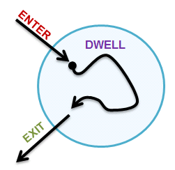
There are three types of notifications: "ENTER", "DWELL", and "EXIT". The distance between the device and the center of each region is calculated every at positioning update. You can define the dwelling period.
After defining the region, the GNSS core continues to monitor transitions. When GNSS core recognizes a state change, it sends a notification to the application.
5.6.8.2. Configuration
To enable geofencing, set GNSS device and Geofence Support to Y.
[System Type]
[CXD56xx Package Configuration]
[GNSS device] (CXD56_GNSS) = Y
[Geofence Support] = Y
5.6.8.3. Add Region and Setup Options
Applications open /dev/geofence to use the Geofence feature.
To add a Region and set the Geofence options, use the following ioctl commands from /dev/geofence.
5.6.8.3.1. CXD56_GEOFENCE_IOCTL_ADD
This command adds regions. You can define up to twenty regions. Each region is defined by:
-
Latitude
-
Longitude
-
Radius
All north latitude and east longitude values are positive. However, do not use a plus sign ("+") prefix with these values. All south latitude or west longitude values are negative. Important: Use a minus sign ("-") prefix with these values. Specify radius values in meters.
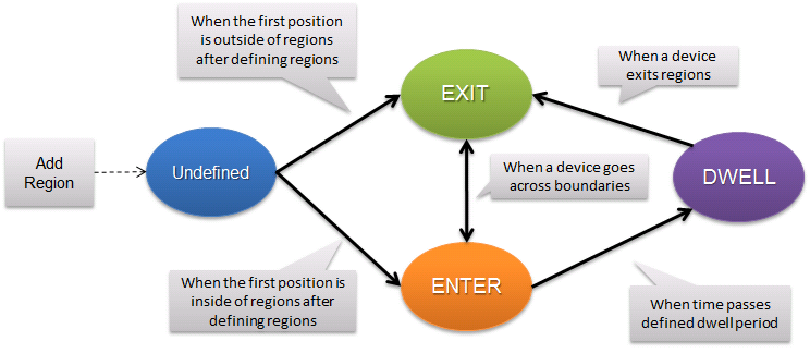
5.6.8.5. Dead Zone
To reduce excess notifications due to position fluctuations, you can define a dead zone within a circular boundary.
The dead zone is defined as follows:
-
The ENTER boundary defines the dead zone’s inner circle
-
The EXIT boundary defines the dead zone’s outer circle
The state does not change as a device moves inside a dead zone.
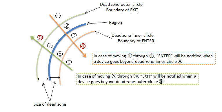
5.6.8.6. Read Geofence Transition Data
You can determine a Geofence state change using the poll method. After you add a region, the Geofence status is always notified of the position. After that, the Geofence status is notified only when the state is updated.
The transition data structure is cxd56_geofence_status_s. For more information, see the application example Geofencing Transitions.
5.6.9. PVTLog
5.6.9.1. Key Features
PVTLog is a function that logs position, velocity, and time information in the GNSS core. PVT stands for position, velocity, and time.
You can store up to 170 logs in the GNSS core. When the specified number of logs is stored, the application is notified using the signal method. For example, if you log PVT every 15 minutes, GNSS can store logs for 42 hours continuously independent of the application.
For more information on logging data, see the cxd56_pvtlog_s structure.
5.6.9.2. Configuration
When you use PVTLog, set GNSS device support to Y.
[System Type]
[CXD56xx Package Configuration]
[GNSS device] (CXD56_GNSS) = Y
5.6.9.3. Start and Stop Log Store
To start log store, use the ioctl command CXD56_GNSS_IOCTL_PVTLOG_START. This command sets the log store interval to the specified number of notifications. The log store interval is longer than the position interval. Logging starts when position starts.
To stop log store, use the ioctl command CXD56_GNSS_IOCTL_PVTLOG_STOP.
5.6.9.4. Notification
When the specified number of logs are saved in the log store, the application is notified by the signal method using CXD56_GNSS_SIG_PVTLOG.
After this notification, the application must read log data before the next log is saved. The log data in the GNSS core is deleted each time a new log is created.
The application can read log data at the offset location CXD56_GNSS_READ_OFFSET_PVTLOG.
| The log data in the GNSS core is located in backup RAM. Data is stored there before logging begins is not deleted. To start a new log store, start logging after calling the delete command CXD56_GNSS_IOCTL_PVTLOG_DELETE_LOG. |
For more information on PVT logging, see the application example PVTLog.
5.6.10. GNSS Performance
5.6.10.1. Trajectory
This section displays each figure of GNSS positioning trajectory using either the built-in chip antenna mounted on the main board of Spresense or an external GNSS antenna needed to be repaired. the figure of trajectory using the external antenna shows more accurately than the case using the built-in chip antenna because of raising sensitivity a little.
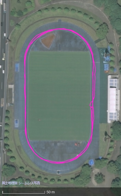
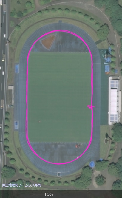
- Conditions
-
-
Satellite system: GPS + GLONASS
-
Environment: good signal conditions under open sky
-
Pre-condition: keep capturing some satellite after fix positioning once before jogging
-
Antena position: the antenna with an upper arm is swung while jogging
-
Speed: light jogging (about 6km/h)
-
- Actual Trajectory
-
-
3 laps on a 400m track (The cource position is inside the track).
-
|
The above pictures created from maps provided by "© OpenStreetMap contributors" and licensesd by Creative Commons Attribution-ShareAlike 2.0. |
| These trajectory are drown on the OpenStreetMap with each GPX data coverted from the NMEA output. |
5.6.11. Application Examples
5.6.11.1. Notify Positioning
This example demonstrates GNSS positioning notification. It notifies using the poll or signal method. The method can be selected using the config settings CONFIG_EXAMPLES_GNSS_USE_SIGNAL or CONFIG_EXAMPLES_GNSS_USE_POLL.
5.6.11.3. Introduction
The gnss_atcmd is a sample application for evaluating GNSS functions on the Spresense SDK.
If you send a command via a serial port from a host such as a PC, the result of the NMEA sentences are outputted to that serial port. The command specification and usage of the application will be described in this document later.
5.6.11.4. @Command specification
This section explains the specifications of commands sent from the host.
The gnss_atcmd application receives a command sent from a host such as a PC, and returns the processing result to the host. NMEA is not output during the period from the command transmission until the result is sent. Please do not issue another command before the response message (Done or Err) is returned. The time from sending the command to get the command response, which depends on the type of command and the state, may take about 5 seconds in the worst case. When timeout is detected by the host controller, please expect a timeout for 5 seconds.
5.6.11.4.1. Command format
Command format is shown below. After sending "@" (at mark), send a command string and argument, and send a carriage return and a line feed code at the end.
@Command [Argument0] [Argument1]...<CR><LF>
- Command
-
string of 4 characters or less. See command list for more details.
- Argument
-
number in decimal. If the beginning of string is "0x", it represents a hexadecimal number. Depending on the command, multiple arguments are taken.
- <CR><LF>
-
Represents CR(Carriage Return) and LF (Line Feed)
5.6.11.4.2. Normal response format
Normal response format is shown below. [Sent command string] and "Done" are replied.
[Command] Done<CR><LF>
- Command
-
Received command string
- <CR><LF>
-
Represents CR(Carriage Return) and LF (Line Feed)
5.6.11.4.3. Error response format
Error response format shows below. [Sent command string], "Err" and error code are replied.
[Command] Err ErrorCode<CR><LF>
- Command
-
Received command string
- ErrorCode
-
negative value of error code
- <CR><LF>
-
Represents CR(Carriage Return) and LF (Line Feed)
5.6.11.4.4. Command sequence
If @GCD command is issued, NMEA sentences will be replied periodically after "Done" is replied.
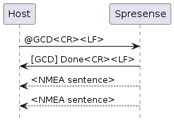
If @VER command is issued, "Done" will be replied after the version information.
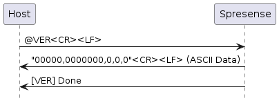
5.6.11.4.5. Command list
Below is a list of commands that gnss_atcmd can process.
| Command | Argument | Description | ||||||||||||||||||||||||||||||
|---|---|---|---|---|---|---|---|---|---|---|---|---|---|---|---|---|---|---|---|---|---|---|---|---|---|---|---|---|---|---|---|---|
@AEXT |
- |
Stop application. Please execute this command while positioning is stopped. |
||||||||||||||||||||||||||||||
@BSSL |
bit mask of NMEA sentence to output |
Of NMEA sentences defined in the NMEA 0183 (ver 4.00) standard, specify the NMEA sentence to output as a bit mask value to an argument. In the initial state, 0xef is set to the NMEA mask.
xx means talker ID as below:
Example of command:
|
||||||||||||||||||||||||||||||
@BUP |
- |
Save ephemeris and other information into flash. The saved data will be automatically restored the next started-up time. Please execute this command while positioning is stopped. |
||||||||||||||||||||||||||||||
@GCD |
- |
Forces cold start positioning and outputs NMEA sentences periodically. |
||||||||||||||||||||||||||||||
@GNS |
bit mask of selected satellites |
Select the bit mask of satellites used for positioning.
NOTE
GLONASS, Galileo and BeiDou cannot be used at the same time. For details, see Select positioning and augmentation satellite systems. Example of command:
|
||||||||||||||||||||||||||||||
@GPOE |
<latitude[degree]> |
Set present location in ellipsoidal coordinates. Example of command:
|
||||||||||||||||||||||||||||||
@GSR |
- |
If possible, start positioning using hot start and outputs NMEA sentences periodically. |
||||||||||||||||||||||||||||||
@GSTP |
- |
Stop positioning |
||||||||||||||||||||||||||||||
@GSW |
- |
Forces warm start positioning and outputs NMEA sentences periodically. |
||||||||||||||||||||||||||||||
@GTIM |
<Year> |
Set UTC time Example of command:
|
||||||||||||||||||||||||||||||
@VER |
- |
Return the version number of all zero. |
5.6.11.5. Usage of application
This chapter shows an example of operation of the gnss_atcmd application.
5.6.11.5.1. Configuration
In order to run this application, enable the following SDK Configuration.
CONFIG_CXD56_GNSS=y
CONFIG_GPSUTILS_CXD56NMEA_LIB=y
CONFIG_EXAMPLES_GNSS_ATCMD=yThese configurations can be automatically enabled by executing the following command.
./tools/config.py examples/gnss_atcmd
In addition, the port used for command input/output can be switched by the configuration GNSS Command IO.
│ Prompt: GNSS Command IO │ Location: │ -> Examples │ -> GNSS CXD5603 @command emulator example (EXAMPLES_GNSS_ATCMD [=y])
-
Example uses USB CDC tty : Use USB port on the extension board (default)
-
Example uses STDINOUT for nsh debug UART : Use USB port on the main board (UART1)
-
Example uses UART ttyS0 : Use USB port on the main board (UART1)
-
Example uses UART ttyS1 : Not supported
-
Example uses UART ttyS2 : Use UART port on the main or extension board (UART2)
After the gnss_atcmd application is executed via nsh prompt, input commands as mentioned above.
5.6.11.5.2. e.g. Start positioning using cold start and stop positioning
The application starts positioning using cold start with selecting GPS, Glonass and QZSS L1C/A as satellites. NMEA sentences are outputted for a short period of time. After that, the application stops positioning and exits.
nsh> gnss_atcmd (Start application)
@GNS 0x0b↵ (Select satellites)
@GCD↵ (Cold Start positioning)
----- <NMEA output> ----
@GSTP↵ (Stop positioning)
@AEXT↵ (Finish application)
nsh>
5.6.11.5.3. e.g. Start positioning using hot start
At first, the application starts positioning using cold start with selecting GPS, Glonass and QZSS L1C/A as satellites. After positioning, the application stops the GNSS while keeping the power supply of Spresense. At next, the application starts positioning using hot start. Hot start will be fixed after a few seconds of starting positioning.
nsh> gnss_atcmd (Start application)
@GNS 0x0b↵ (Select satellites)
@GCD↵ (Cold Start positioning)
----- <NMEA output> ----
@GSTP↵ (Stop positioning)
@AEXT↵ (Finish application)
nsh> gnss_atcmd (Start application)
@GSR↵ (Hot Start positioning)
----- <NMEA output> ----
@GSTP↵ (Stop positioning)
@AEXT↵ (Finish application)
nsh>
5.6.11.5.4. e.g. Start positioning using hot start across Spresense power cycle
At first, the application starts positioning using cold start with selecting GPS, Glonass and QZSS L1C/A as satellites. After positioning, Spresense’s power is turned off. At next power cycle, Spresense is turned power on, and the application set current UTC time and present location. The application starts positioning using hot start. Hot start will be fixed after a few seconds of starting positioning.
nsh> gnss_atcmd (Start application)
@GNS 0x0b↵ (Select satellites)
@GCD↵ (Cold Start positioning)
----- <NMEA output> ----
@GSTP↵ (Stop positioning)
@BUP↵ (Backup into flash)
@AEXT↵ (Finish application)
----- <Power OFF> -----
----- <Power ON> -----
nsh> gnss_atcmd (Start application)
@GTIM 2018 11 09 02 45 05↵ (Set UTC time)
@GPOE 35 39 31 139 44 05↵ (Set present location)
@GSR↵ (Hot Start positioning)
----- <NMEA output> ----
@GSTP↵ (Stop positioning)
@AEXT↵ (Finish application)
nsh>
5.6.11.5.5. Output of Michibiki(QZSS) QZQSM sentences
Select QZSS L1 / CA as the satellite mask, activate the QZQSM sentence with the NMEA mask, and start positioning. If the reception conditions are good, the first QZQSM sentence will be output in less than 10 seconds, and will be output every 4 seconds thereafter.
nsh> gnss_atcmd
@GNS 0x29↵
@BSSL 0x40ef↵
@GCD↵
$GPGGA,000001.00,,,,,0,00,,,,,,,*49
$GNGLL,,,,,000001.00,V,N*55
…
$GNZDA,000008.00,06,01,1980,,*77
$QZQSM,56,9AADF260540002C3F2587F8B101962082C41A588ACB1181623500011439023C*7B
$GPGGA,000009.00,,,,,0,00,,,,,,,*41
…
5.7. ASMP Framework
5.7.1. General
The Spresense ASMP framework is designed for multi-core architecture processors, based on NuttX. It defines two tasks:
-
Supervisor task (runs on the main CPU)
-
Worker task (runs on the coprocessor)
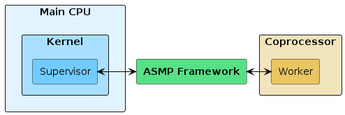
The Worker task executes on the coprocessor, independently from the main CPU.
The Supervisor task uses the ASMP framework API to control the lifecycle of the Worker task operations. For details, see MP Task.
The ASMP framework provides the following functions for the Supervisor and Worker tasks to communicate with each other.
MP message queue is a message exchange interface similar to the POSIX message queue.
MP mutex provides a mechanism for exclusive control similar to pthread mutex.
MP shared memory provides a memory area shared by each task.
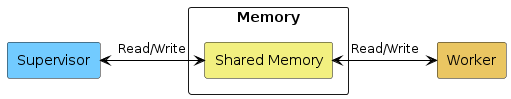
5.7.2. Configuration
The ASMP framework requires a memory area outside the kernel management for shared memory between tasks that can be controlled by the ASMP shared memory size option. If the framework is not used, the full 1.5 MB memory can be used by the kernel.
Set the ASMP Shared memory size setting in memory blocks of 128 KB (0x20000).
|
[ASMP] = Y [ASMP shared memory size] = 0x100000
5.7.3. Worker Task Startup Sequence
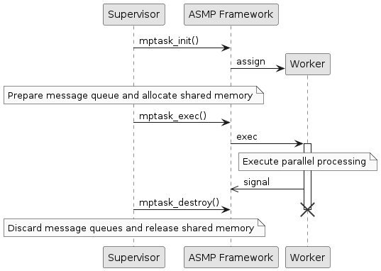
-
Call mptask_init to generate a Worker task.
-
Prepare a message queue and allocated shared memory if necessary. Bind it to the Worker task using mptask_bindobj.
-
Execute the Worker task by calling mptask_exec.
-
Call mptask_destroy to stop the Worker task.
-
If a message queue and shared memory was created, discard it.
For details, please refer to Supervisor Task example and Worker Task example.
5.7.4. Building a Worker Task
The Worker task loads and executes a file in ELF format. As the Worker task executes on the coprocessor, it is not able to make direct calls to the kernel or SDK API.
The layout of the ELF file supported by ASMP framework is as follows:
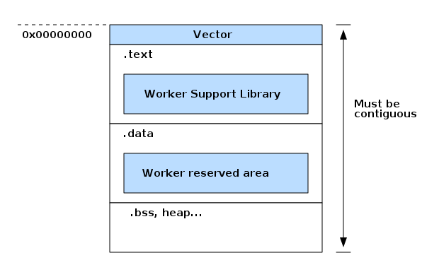
Each program’s start address must be 0x00000000 and each section must be contiguous.
The SDK provides compiler options, linker options and linker scripts necessary to generate ELF files for the Worker task.
These are defined in sdk / Make.defs as CELFFLAGS and LDRAWELFFLAGS respectively. For specific build rules please refer to ASMP Worker Task 'Hello World' example.
In order to use ASMP framework with the Worker task, a library for the Worker task has to be generated before building the Worker task. This library contains the necessary code (blue colored regions in the figure) for configuring the Worker task.
Refer to Worker Task Makefile and Worker Task Library Makefile for sample code to generate a library for the Worker task.
5.8. Sensor Control Unit
5.8.1. Overview
The Sensor Control Unit (SCU) can receive data from sensor devices connected by the SPI and I2C buses. It is designed to reduce processor load and power consumption.
Your application can control the following SCU operations:
-
Automatically receives sensor data from the sequencer.
-
Performs decimation processing for received sensor data.
-
Applies IIR filters.
-
Notifies the application of events.
The SCU has the following components:
-
One SPI bus
-
Two I2C buses
-
Eight sequencers
-
Two decimators
The following diagram shows the functional relationship of the SCU with other components:
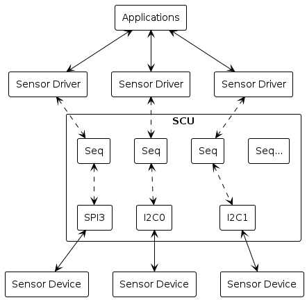
5.8.2. Configuration
CXD56xx Configuration --->
Sensor Control Unit (SCU) --->
Sequencer Sampling Predivider = 64 (default) (1)
SCU clock mode = RCOSC (default) (2)
SCU32K clock source = RTC (default) (3)
SCU Decimator assignments (4)
...
(Decimator supported drivers)
...
SCU Debug = N (default)
DMAC support = Y (default)
| 1 |
Sequencer Sampling Predivider sets the sequencer sampling rate. |
| 2 |
SCU clock mode sets the clock to run. |
| 3 |
SCU32K clock source sets the source of the SCU sampling base clock at 32768Hz. |
| 4 | You can assign the SCU Decimator assignments option to a decimator-supported sensor.
You can enable three or more sensors. open() fails if you call it when two decimators are in use. |
5.8.3. Sequencer
The SCU has two sequencer types:
-
The normal sequencer receives sensor data periodically and saves it to FIFO.
-
SCU uses a sequencer device driver that reads from FIFO.
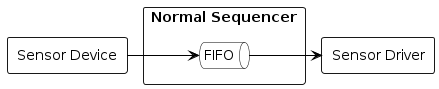
Each sequencer’s FIFO is assigned a configurable size using SCUIOC_SETFIFO. The total FIFO memory is 40KB. Your application must set this before using the SCU supported driver.
ret = ioctl(fd, SCUIOC_SETFIFO, sizeof(struct three_axis_s) * 128);The sequencer chooses the sensor data by sampling the rate independent of the sensor
device. Your application must set the sequencer sampling rate using SCUIOC_SETSAMPLE.
ret = ioctl(fd, SCUIOC_SETSAMPLE, 2);SCUIOC_SETSAMPLE is the binary clock divider.
To calculate the sequencer sampling rate:
Sequencer sampling rate = 32768 / CONFIG_CXD56_SCU_PREDIV / (2 ^ n)
For example, to set the sequencer sampling rate to 128 Hz:
-
Set
CONFIG_CXD56_SCU_PREDIVto 64 (the default value) -
Set
SCUIOC_SETSAMPLEto 2
| The sequencer sampling rate is different from the sensor sampling rate. Your application must set separate values for each rate. |
The SCU driver signals the application when the sampling data in the sequencer FIFO reaches the watermark value SCUIOC_SETWATERMARK.
For example, to make the SCU signal every 1 second:
-
Set the sampling rate to 128 Hz
-
Set the watermark to 128
wm.signo = CONFIG_EXAMPLES_MAG_SIGNO;
wm.ts = &ts;
wm.watermark = 128;
ret = ioctl(fd, SCUIOC_SETWATERMARK, (unsigned long)(uintptr_t)&wm);The siginfo data structure contains the timestamp of the watermark signal.
5.8.4. Decimator
The decimator is a sequencer feature that performs decimation processing. Your application must handle sensor data from only one sensor device. The decimator has three FIFOs for storing sensor data.
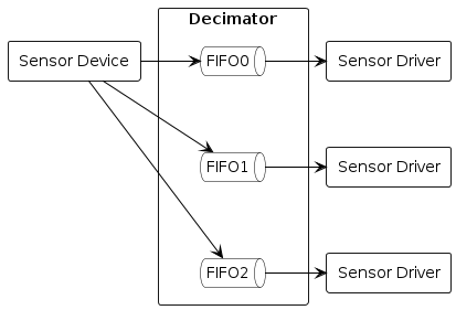
5.8.4.1. Decimation Processing
The decimator processes sample data at the sequencer sampling rate. The decimation process applies a CIC filter. Your application can set the decimation parameters using SCUIOC_SETDECIMATION using the decimation_s data structure:
struct decimation_s dec;
dec.ratio = 1;
dec.leveladj = SCU_LEVELADJ_X1;
dec.forcethrough = 0;
ret = ioctl(d->fd, SCUIOC_SETDECIMATION, (unsigned long)(uintptr_t)&dec);The ratio member specifies the pick up ratio against the sampling rate in exponents of 2. For example, if the sampling rate is 64 Hz and ratio is set to 1 ( 64 / (2 ^ 1) ), the effective sampling rate is 32 Hz. Setting ratio to 0 makes no change to the sampling rate, but the decimation process applies CIC filter logic to the sample data. To disable the CIC filter, set forcethrough to 1.
5.8.4.2. Amplification
Decimation can amplify sampling data using the leveladj member. Amplified sampling data is saturated to its data width.
leveladj can use these constants:
-
SCU_LEVELADJ_X1(x1) -
SCU_LEVELADJ_X2(x2) -
SCU_LEVELADJ_X4(x4) -
SCU_LEVELADJ_X8(x8)
5.8.5. Sensor Data Processing
The SCU has sensor data processing for taking sampling data. The sensor data processing unit contains:
-
An IIR filter
-
An event detector
Your application can specify 1 to 3 sensor data processing units. Each unit is connected to a FIFO.
5.8.5.1. IIR Filter
The SCU can use two IIR filters for sampling data.
Your application can set the IIR filters to any combination of positions. FIFO is the sequencer’s decimator FIFO. Event Detector is an SCU function.
The IIR filter position settings are shown in the following diagram:
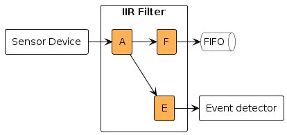
-
A - Apply SCU to FIFO and event detector
-
F - Apply SCU only to FIFO
-
E - Apply SCU only to event detector
You can apply the two IIR filters as follows:
-
Both filters to FIFO and event detector
-
One filter to both FIFO and event detector, one to FIFO
-
One filter to both FIFO and event detector, one to event detector
-
Both filters to FIFO
-
Both filters to FIFO and Event detector
-
Both filters to event detector
IIR filter position settings are defined by the enumeration filter_pos_e.
The IIR filter can be configured using coefficients:
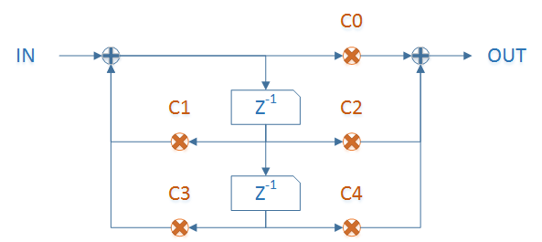
Each coefficient is a 34-bit fixed point number in s2.31 format. IIR filter coefficients are structured as 32-bit (h) and 8-bit (l) values in the iir_coeff_s data structure:
The coefficient structure is shown in the following diagram:
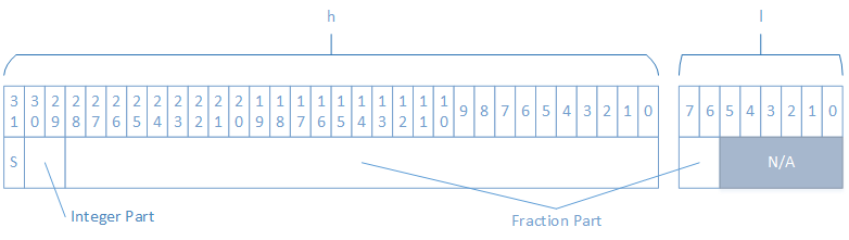
Bit 31 of h is S, which specifies the coefficient’s sign: 0 = plus, 1 = minus.
Bits 30 to 29 of h are the coefficient’s integer value.
Bits 28 to 0 of h and bits 7 to 6 of l are the coefficient’s fractional part.
5.8.5.2. Event Detector
The event detector is a monitoring feature of sensor data processing. Your application can determine the timing of the sensor data.
The event detector counts input sensor data as high or low compared to a configured threshold. The event detector can handle 16 bits per sample and 1-, 2-, or 3-axis data. If the input is 2- or 3-axis data, it normalizes this data before counting. If the counted value reaches the threshold, the event detector sends an interrupt. Your application receives this event as a signal with a timestamp.
The normalization calculation depends on the number of axes:
-
For 1 axis (X):
norm = abs(x)
-
For 2 axes (X, Y):
norm = max(abs(x), abs(y)) * 123 / 128 + min(abs(x), abs(y)) * 51 / 128
-
For 3 axes (X, Y, Z):
L1 = max(abs(x), abs(y)) * 120 / 128 + min(abs(x), abs(y)) * 49 / 128 norm = max(L1, abs(z)) + min(L1, abs(z)) * 44 / 128
You configure the event detector with the scuev_notify_s data structure. The rise and fall members control event detection. Each of these members have:
-
threshold -
count0 -
count1
The SCU notifies the application when the input data count reaches count0 + count1.
The event detector requires IIR filter output. You must configure the IIR filter before you configure the event detector.
The event detector works according to these rules:
-
Count values that are greater than the specified threshold.
-
If the count reaches
count0, begin to count. -
If the input data falls below the specified threshold before reaching
count0, stop and reset the count. -
If the total count reaches
count0+count1, send ariseevent. -
If
count1is zero, send a notification when the count reachescount0. -
If the or
count0is 0, ignore the configuration.
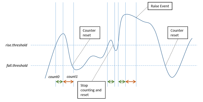
5.8.6. Restrictions
The decimator, IIR Filter, and event detector can be programmed only for the following data formats:
-
16-bit data per sample
-
1, 2, or 3 elements
The decimator can accept any data format, but processes only data duplication when it is given data other than the above formats.
5.8.7. For Driver Developers
Developers of SCU-supported drivers must:
-
Understand sequencer instructions
-
Configure the sensor device using a special transfer API
-
Open the sequencer and connect with the sensor driver
-
Read sampling data from the sequencer
-
Pass
ioctlcommands to the sequencer
5.8.7.1. Understanding Sequencer Instructions
The SCU sequencer sends and receives data through SPI and I2C buses using a specific instruction format. Specify sequencer instructions as an array of uint16_t values. Use the SCU_INST_SEND and SCU_INST_RECV macros to set sequencer instruction values.
This series of instructions tells the sequencer how to transfer data with the sensor device. Include the special termination indicator SCU_INST_LAST at the end of the instruction array.
Examples of instruction arrays:
inst[0] = SCU_INST_SEND(0x00); // Send register address 0x00
inst[1] = SCU_INST_RECV(2) | SCU_INST_LAST; // Read 0x00 and 0x01 address data, and indicate the last of instructions5.8.7.2. Configure Sensor Device with Transfer API
Initialize the driver for the target device. The SCU supported driver must use scu_spitransfer or scu_i2ctransfer to access device registers. Use these functions with the sequencer instruction macro SCU_INST_SEND, as shown in this register write access example:
static void sensor_putreg8(FAR struct sensor_dev_s *priv, uint8_t regaddr, uint8_t regval)
{
uint16_t inst[2];
/* Send register address and set the value */
inst[0] = SCU_INST_SEND(regaddr);
inst[1] = SCU_INST_SEND(regval) | SCU_INST_LAST;
scu_i2ctransfer(priv->port, priv->addr, inst, 2, NULL, 0);
}| The SPI and I2C bus contolled by SCU can be accessed directly. If you access them from the SCU and sensor driver through the same bus at the same time, it causes a bus conflict. Use the APIs as shown above to avoid conflicts. |
5.8.7.3. Open/Close Sequencer
The SCU driver handles sequencer object operations. Each sensor driver must include a sequencer object. In this example, a sequencer object is stored in device data:
g_seq = seq_open(MAG_SEQ_TYPE, SCU_BUS_I2C0);
if (!g_seq)
{
return -ENOENT;
}
priv->seq = g_seq;The decimator can be read from three FIFOs. Create three device files to read data from different applications. In this case, you must call seq_open() once, because the decimator replicates sensor data to three FIFOs. Count the number of references to avoid multiple initializations.
if (g_refcnt == 0)
{
int ret;
ret = sensor_seqinit(priv);
if (ret < 0)
{
return ret;
}
}
else
{
/* Set existing sequencer */
priv->seq = g_seq;
}
g_refcnt++;The SCU can sleep when no sequencers are running. The SCU sleep function supports seq_open() and seq_close(). Call these functions from the open() and close() driver interfaces respectively. The driver can also use them to control device power mode and reduce power consumption.
5.8.7.4. Read Sampling Data from Sequencer
Set the instructions for the sequencer to receive sensor data using seq_setinstruction:
Examples of reading a sample data of SENSOR_BYTESPERSAMPLE from SENSOR_DATA_REGISTER:
static const uint16_t g_sensorinst[] =
{
SCU_INST_SEND(SENSOR_DATA_REGISTER),
SCU_INST_RECV(SENSOR_BYTESPERSAMPLE) | SCU_INST_LAST,
};seq_setinstruction(priv->seq, g_sensorinst, itemsof(g_sensorinst));Sensor data is sent to the FIFO that is assigned to the sequencer. The driver can read from its FIFO using seq_read(). The driver reads sensor data and stores it in the application buffer:
len = seq_read(priv->seq, priv->id, buffer, len);5.8.7.5. Pass ioctl Commands to Sequencer
To pass SCU ioctl commands from sensor drivers to the sequencer, use seq_ioctl(). Call seq_ioctl() from each driver’s ioctl command if it is a valid SCU IO command. Use the _SCUIOCVALID() macro to determine whether the command is valid.
For example:
if (_SCUIOCVALID(cmd))
{
/* Redirect SCU commands */
ret = seq_ioctl(priv->seq, priv->id, cmd, arg);
}5.9. Memory Utility Libraries
5.9.1. Overview
The media & sensor processing functions requires safe handling of big memory chunks without causing leakage in the form of fragmentation. For this reason Spresense SDK provides a memory utility library.
The library consists of the following three libraries, "Memory Manager", "Message Library", "Simple FIFO".
-
The "Memory Manager" manages memory between tasks.
-
It has a fixed size memory pool library that implicity manages segment areas.
-
-
"Message Library" is a library for sending and receiving class objects between tasks in order to use "Memory Manager".
-
"Simple FIFO" is the basic FIFO used to transfer data between applications and a framework.
The use of these libraries is premised on media processing & sensor processing. Details are described in the following chapters.
5.9.2. Memory Manager
This chapter will explain the function of the "Memory Manager".
5.9.2.1. Overview
"Memory Manager" is a fixed-size memory pool that manages implicit acquisition and release of memory. It is possible to acquire and release the memory as necessary by defining the memory area as a memory pool and securing needed segments in it.
To avoid memory fragmentation a pool type, number of segments and allocation memory area can be defined.
This allocation information is called memory_layout, this layout can be switched according to the needs of the application and securing the necessary memory for each function.
This memory_layout can be freely decided and created according to the needs of the application. How to create the memory_layout is described in Configurations and Generate.
Acquiring the needed memory segment is done by creating a MemHandle object and calling the API to clam the segment. Claimed segments this way are guaranteed as long as the MemHandle object isn’t destroyed. This is also guaranteed in the case that multiple users claim and release MemHandle asynchronously until all users have released the MemHandle.
5.9.2.2. Mechanism of segment acquisition and release
Each instance of MemHandle need to point to the a segment of the required memory area. By calling the API that will acquire the segment area will secure the memory segment that is associated with the handle.
When the segment has been acquired, the reference counter of the segment is increased by 1. As a result, the segment area is in use and managed so that it can not be used from other requests.
The reference counter will also be incremented by 1 by the operator = and the Copy Constructor.
By copying this instance of MemHandle to the object located next to the data pipeline and passing it, you can refer to segments attached to "MemHandle" and the area is guaranteed.
When MemHandle isn’t needed anymore, the reference counter will be decremented by -1 by the Destructor.
When the reference counter is down to 0, all linked memory segments will be released.
This mechanism enables it to safely allocate and free shared memory asynchronously between different tasks.
To use memory_layout a header file group has to be prepared in advance.
These header files are created by creating a Memory Layout definition file (mem_layout.conf) and using a dedicated tool(mem_layout.py).
5.9.2.3. APIs
The interface of "Memory Manager" is as follow. For details, see memutils_memory_manager.
5.9.2.3.1. Functions of the Manager class
static err_t Manager::initFirst(void* lib_area, uint32_t area_size)
void * lib_area: Data area used by the library uint32_t area_size: size of area (in bytes)
ERR_OK: initialization succeeded ERR_STS: This function is executed more than once ERR_DATA_SIZE: area_size is less than sizeof(MemMgrLite::Manager) ERR_ADR_ALIGN: lib_area is not a multiple of 4
Initialize the entire library. When the fence function is effective, initialize the fence of FixedArea. Before using other APIs in this library, // once with a single CPU agreed in advance to execute this function only. The argument lib_area specifies the address of the data area for the library. If the address is not a multiple of 4, ERR_ADR_ALIGN is returned. The area to be specified is an area having a permanent life. In terms of performance, SRAM High speed memory is desirable. The area_size argument specifies the size of lib_area in units of bytes. If the size is less than sizeof(MemMgrLite::Manager), ERR_DATA_SIZE is returned. Since the size required for the current implementation is (4 + 4 * NUM_MEM_POOLS), a minimum of 12 bytes The maximum is 1028 bytes. //If you use the optional dynamically generated pool, you can add an additional (8 + 5 * NUM_DYN_POOLS) A size rounded up to a multiple of 4 is required. //When using this library with multi-core (shared pool) support, this area is it must be accessible from all CPUs. //Since ARM TCM, MIPS ScratchPad, etc. are CPU local memory, multicore it can not be specified for lib_area at the time of support.
-
Usage example 1 An example of defining and using the MemMgrLite data area in the memory layout definition file is shown below.
//S_ASSERT(MEMMGR_DATA_AREA_SIZE> = sizeof(MemMgrLite::Manager));
void * lib_data_va = MemMgrLite::translatePoolAddrToVa(MEMMGR_DATA_AREA_ADDR);
if(MemMgrLite::Manager::initFirst(lib_data_va, MEMMGR_DATA_AREA_SIZE))! = ERR_OK)
{
/ * Error handling * /;
}-
Usage example 2 Here is an example that uses the data area of MemMgrLite defined by a static variable.
Since area can be secured with sizeof, there is no worry about size shortage. Note that the area is defined as an array of uint32_t to guarantee 4-byte alignment.
static uint32_t s_lib_data [sizeof(MemMgrLite :: Manager) / sizeof(uint32_t)];
if(MemMgrLite::Manager::initFirst(s_lib_data, sizeof(s_lib_data))! = ERR_OK)
{
/ * Error handling * /;
}static err_t Manager::initPerCpu(void * lib_area)
void* lib_area / * Data area used by library * /
ERR_OK: initialization succeeded ERR_STS: This function is executed more than once, or initFirst() is not executed yet
Initialize each CPU library. The argument lib_area specifies the same address as specified in Manager::initFirst(). If Manager::initFirst() is not executed yet, or if this API is executed again on a CPU that has already executed this API, ERR_STS is returned. //When using this library with multi-core (shared pool) support, all CPUs Wait for Manager::initFirst() to complete execution (in a platform-specific manner) //It is necessary to execute this function.
-
Usage example 1 An example of using the data area of MemMgrLite defined in the memory layout definition file is shown below.
void * lib_data_va = MemMgrLite :: translatePoolAddrToVa(MEMMGR_DATA_AREA_ADDR);
if (MemMgrLite :: Manager :: initPerCpu(lib_data_va))! = ERR_OK)
{
/ * Error handling * /;
}-
Usage example 2 Here is an example that uses the data area of MemMgrLite defined by a static variable.
if (MemMgrLite::Manager::initPerCpu(s_lib_data))! = ERR_OK)
{
/ * Error handling * /;
}static err_t Manager::createStaticPools(uint8_t sec_no,
NumLayout layout_no,
void* work_area,
uint32_t area_size,
const PoolSectionAttr *pool_attr)
uint8_t sec_no : Section layout number (0 origin) NumLayout layout_no : Memory layout number (0 origin) void* work_area : Work area for static memory pool operation uint32_t area_size : size of the work area (in bytes) const PoolSectionAttr* pool_attr : Address of memory layout
ERR_OK : initialization succeeded ERR_STS : initPerCpu() has not been executed or this function has been executed ERR_ADR_ALIGN : work_area is not a multiple of 4 ERR_DATA_SIZE : area_size is less than maximum work area size
Generate a memory pool group with the specified layout number. To change the memory layout, once with Manager::destroyStaticPools() Discarding the memory pool group and then executing this function again. If Manager :: initPerCpu() is not executed yet,or if this function has already been executed, ERR_STS is returned. The argument sec_no specifies the number of the section to be used. The argument layout_no specifies the number of the memory layout to be used. The argument work_area specifies the address of the work area for static memory pool operation. If the address is not a multiple of 4, ERR_ADR_ALIGN is returned. The specified area exists until Manager::destroyStaticPools() is called must be an area. In terms of performance, high-speed memory such as SRAM is desirable. The area_size argument specifies the size of the work area for static memory pool operations. Macro defined for each layout number MEMMGR_Lx_WORK_SIZE (x is a layout number) Specify the above values. The maximum work area size in the entire layout is defined by the macro MEMMGR_MAX_WORK_SIZE. If the size of the work area is insufficient, ERR_DATA_SIZE is returned. //When using this library with multi-core (shared pool) support, this area is it must be accessible from all CPUs. //Since ARM TCM, MIPS ScratchPad, etc. are CPU local memory, multicore it can not be specified when supporting.
| Spresense can select only SRAM. |
static void Manager::destroyStaticPools(uint8_t sec_no)
uint8_t sec_no : Section layout number (0 origin)
None
Discard the static memory pool of the section number generated by Manager::createStaticPools(). When static memory pool is not created, do nothing. If Manager::initPerCpu() has not been executed, "debug_assert" it. When the memory pool is destroyed, the segment release omission is checked. If release leakage is detected, "assert". When the fence check function is valid, a fence check of the static memory pool is performed and if fence failure is detected, "assert" it.
/* Discard static memory pool */
MemMgrLite::Manager::destroyStaticPools(0);static NumLayout Manager :: getCurrentLayoutNo()
None
Currently set memory layout number If not set, BadLayoutNo
Get the current memory layout number. The initial value of the memory layout number is BadLayoutNo. When you call Manager::createStaticPools(), the value specified by the argument is set. Calling Manager::destroyStaticPools() will reset it to its initial value.
/* Get the current memory layout number */
MemMgrLite::NumLayout layout_no = MemMgrLite::Manager::getCurrentLayoutNo();
if (layout_no != MemMgrLite::BadLayoutNo)
{
printf("Current memory layout number: %d\n", layout_no);
}
else
{
printf("Memory layout number not set\n");
}static uint32_t Manager::getStaticPoolsUsedSegs(MemHandle * mhs, uint32_t num_mhs) //static uint32_t Manager::getUsedSegs(PoolId id, MemHandle * mhs, uint32_t num_mhs)
PoolId id: Pool ID MemHandle * mhs: Memory handle array storing the memory segment in use uint32_t num_mhs: Number of elements of the array
Number of segments stored in memory handle array
Store the segment in use in the memory pool in the memory handle array. The reference count of the stored segment increases by one. When the number of segments in use is larger than the value specified by the argument num_mhs, the processing is terminated at the time of storing the segment. getStaticPoolsUsedSegs() targets the entire static pool of the current memory layout. //getUsedSegs() targets static or dynamic memory pools with the specified ID. The argument mhs specifies an empty memory handle array that does not hold memory segments. If the argument id is not a valid pool ID, "debug_assert". "debug_assert" if argument mhs or num_mhs is 0. Before destroying the memory pool, these APIs can be used to specify details of unreleased segments It assumes a purpose of acquiring information. If you only know the number of segments in use, the following one is more efficient. Manager::getPoolNumSegs(id) - Manager::getPoolNumAvailSegs(id)
const uint 32 _ t MaxSegInfo = 8;
MemHandle mhs [MaxSegInfo];
uint32_t num_used = Manager::getStaticPoolsUsedSegs(mhs, MaxSegInfo);
for (uint32_t i = 0; i < num_used; ++i)
{
printf("ID=%u SegNo=%u VA=%08x Size=%u RefCnt=%u\n"
mhs[i].getPoolId(), mhs[i].getSegNo(), mhs[i].getVa(),
mhs [i].getSize(), mhs[i].getRefCnt());
}static bool Manager::isPoolAvailable(PoolId id) static PoolType Manager::getPoolType(PoolId id) static PoolAddr Manager::getPoolAddr(PoolId id) static PoolSize Manager::getPoolSize(PoolId id) static NumSeg Manager::getPoolNumSegs(PoolId id) static NumSeg Manager::getPoolNumAvailSegs(PoolId id) static bool Manager::isPoolFenceEnable(PoolId id) static LockId Manager::getPoolLockId(PoolId id)
PoolId id /* memory pool ID (1 origin) */
See Description
isPoolAvailable() returns whether or not the specified pool ID is valid in the current memory layout. getPoolType(), getPoolAddr(), getPoolSize(), getPoolNumSegs() Returns pool type, address, size, number of segments specified at creation time. getPoolNumAvailSegs() returns the current number of free segments. isPoolFenceEnable() returns the fence specification specified at pool creation time. This function is defined only when fence function is enabled (UseFence = True). //getPoolSpinLockId() returns the spin lock ID specified at pool creation time. This function is defined only when multicore support is enabled (UseMultiCore = True). Since specifying an invalid pool ID will cause a NULL pointer access, Confirm effectiveness and use.
if (MemMgrLite::Manager::isPoolAvailable(my_pool_id))
{
printf("type=%d addr=%08x size=%08x num_seg=%u avail_seg=%u\n",
MemMgrLite::Manager::getPoolType(my_pool_id),
MemMgrLite::Manager::getPoolAddr(my_pool_id),
MemMgrLite::Manager::getPoolSize(my_pool_id),
MemMgrLite::Manager::getPoolNumSegs(my_pool_id),
MemMgrLite::Manager::getPoolNumAvailSegs(my_pool_id));
# ifdef USE_MEMMGR_FENCE
printf(" fence=%u\n", MemMgrLite::Manager::isPoolFenceEnable(my_pool_id));
# endif
//# ifdef USE_MEMMGR_MULTI_CORE
// printf(" spl_id=%u\n", MemMgrLite::Manager::getPoolSpinLockId(my_pool_id));
//# endif
}5.9.2.3.2. Functions of the MemHandle class
MemHandle::MemHandle() // default constructor MemHandle::MemHandle(PoolId id, size_t size) // segment allocate constructor MemHandle::MemHandle(const MemHandle & mh) // copy constructor MemHandle::~MemHandle() // destructor
PoolId id: Pool ID size_t size: Request size (in bytes) const MemHandle & mh: Source memory handle
None
Creates or destroys an instance of MemHandle class. The argument id specifies the pool ID from which the memory segment is acquired. The acquisition result is determined by isAvail() or isNull(). The size argument specifies the requested size. Actually, this argument is used only for comparison with segment size, and segment size If a value exceeding the specified value is specified, it is "debug_assert". The argument mh specifies the copy source memory handle. When the copy source memory handle holds a memory segment The reference count of the memory segment increases by one. The destructor of the instance holding the memory segment is stored in the Decrement the reference count by one.
MemMgrLite::MemHandle mh(MY_POOL_ID, sizeof(MyData));
if(mh.isNull())
{
/* Error handling */;
}MemHandle::MemHandle& operator = (const MemHandle & mh)
const MemHandle& mh: Source memory handle
Reference to itself
Assigns an instance when its value is different from the value of the copy source. In the same case do not do anything. If a memory segment is held, it is necessary to set memory segment Decrement the reference count by one. When the copy source memory handle holds a memory segment Increment the reference count of memory segments by 1 after assignment.
MemMgrLite::MemHandle mh; /* default constructor */
mh = src_mh; /* call operator = () */err_t MemHandle::allocSeg(PoolId id, size_t size, MemHandleProxy& proxy)
PoolId id: Pool ID size_t size: Request size(in bytes) MemHandleProxy& proxy: Memory segment reference
ERR_OK: Successful acquisition ERR_DATA_SIZE: size exceeds segment size ERR_MEM_EMPTY: There are no segments available
Get memory segment from the specified memory pool. The argument id specifies the pool ID from which the memory segment is acquired. The size argument specifies the requested size. Actually, this argument is used only for comparison with segment size, and if a value exceeding the specified value is specified, ERR_DATA_SIZE is returned. If there is no segment that can be acquired, ERR_MEM_EMPTY is returned.
MemMgrLite::MemHandle mh;
if (mh.allocSeg(MY_POOL_ID, sizeof(MyData))! = ERR_OK)
{
/* Error handling */;
}void MemHandle::freeSeg()
None
None
Explicitly free memory segments without relying on destructors. If the memory segment is not held, do nothing. When holding a memory segment, the reference count of the memory segment is set to decrease by 1 and reinitialize the instance.
bool MemHandle::isAvail() bool MemHandle::isNull() bool MemHandle::isSame(const MemHandle & mh) PoolId MemHandle::getPoolId() NumSeg MemHandle::getSegNo() PoolAddr MemHandle::getAddr() PoolSize MemHandle::getSize() SegRefCnt MemHandle::getRefCnt()
const MemHandle & mh: comparison memory handle
See Description
isAvail() returns whether or not the instance holds a memory segment. isNull() returns whether or not an instance holds a memory segment. isSame() returns whether or not the instance and argument mh are the same value. If getPoolId() holds a memory segment for the instance,returns the ID of the pool to which the segment belongs. If it does not hold a segment, it returns NullPoolId. If getSegNo() holds the memory segment for the instance, returns the segment number (1 origin) in the pool to which the segment belongs. If it does not hold a segment, it returns NullSegNo. If getSegAddr() holds the memory segment for the instance, returns the address of the segment. If it does not hold a segment, it is "debug_assert". If getSegSize() holds the memory segment for the instance, returns the size of the segment. If it does not hold a segment, it is "debug_assert". If getRefCnt() holds memory segments for the instance, returns the reference count of the segment. If it does not hold a segment, it is "debug_assert".
If you want to add user’s unique definitions, you would be recommand to define that starts with "U_" in the MemoryLayout file.
Example of writing user-defined constants
# Start with "U_" so that it does not overlap with the definition in the script and let's only capital letters, numbers and "_" # When defined with a name that begins with "U_MEM_", macros with the same name are output to the header file U_STD_ALIGN = 8 # standard alignment U_MSGQ_ALIGN = 64 # message queue area alignment
Define various Memory devices. These definitions are used to define fixed areas. It is output as a name_ADDR macro and a name_SIZE macro in the header file.
MemoryDevices.init( # name ram addr size ["AUD_SRAM", True, 0x000c0000, 0x00040000], None # end of definition )
The explanation of each parameter is as follow.
| name | device name (3 or more characters, starting with upper case letters, capital letters, numbers, "_" can be used) |
|---|---|
ram |
True if the device is RAM. Otherwise False. |
addr |
address of the region. Specify a value of a multiple of 4 except 0. |
size |
size of the region. Specify a value of a multiple of 4 except 0. |
Define an area for each memory device.
The start address of each area is determined by the cumulative size, align, fence for each device.
It is output as a name_ALIGN, name_ADDR, name_SIZE macro in the header file.
Description example of fixed area definition
FixedAreas.init( # name, device, align, size, fence ["AUDIO_WORK_AREA", "AUD_SRAM", U_STD_ALIGN, 0x0003e000, False], # Audio work area ["MSG_QUE_AREA", "AUD_SRAM", U_STD_ALIGN, 0x00001000, False], # message queue area ["MEMMGR_WORK_AREA", "AUD_SRAM", U_STD_ALIGN, 0x00000200, False], # MemMgrLite WORK Area ["MEMMGR_DATA_AREA", "AUD_SRAM", U_STD_ALIGN, 0x00000100, False], # MemMgrLite DATA Area None # end of definition )
The explanation of each parameter is as follow.
| Parameter | Description |
|---|---|
name |
area name (name starting with uppercase letters and ending with "_ AREA", uppercase letters, numbers, _ can be used) |
device |
Device name of MemoryDevices to reserve space |
align |
Start alignment of the region. Specify a multiple of MinAlign (= 4) except 0. |
size |
size of the region. Specify a value of a multiple of 4 except 0. |
fence |
Specify whether the fence is valid or invalid. (This item is ignored if UseFence is False) |
Define the memory pool layout.
The start address of each pool area is determined by the cumulative size, align, fence for each fixed area.
In the header file, pool ID and NUM_MEM_POOLS, NUM_MEM_LAYOUTS and
Lx_name_ALIGN, Lx_name_ADDR, Lx_name_SIZE, Lx_name_NUM_SEG, Lx_name_SEG_SIZE are output as a macro. (x is the layout number)
If the fence is valid, the Lx_name _ L _ FENCE and L x _ name _ U _ FENCE macros are also output.
Description example of .PoolLayout definition
# Definition for player
U_MAIN_BUF_SIZE = 1024
U_MAIN_BUF_SEG_NUM = 4
U_MAIN_BUF_POOL_SIZE = U_MAIN_BUF_SIZE * U_MAIN_BUF_SEG_NUM
U_PCM_BUF_SIZE = 1024
U_PCM_BUF_SEG_NUM = 8
U_PCM_BUF_POOL_SIZE = U_PCM_BUF_SIZE * U_PCM_BUF_SEG_NUM
# Definition for recorder
U_REC_BUF_SIZE = 2048
U_REC_BUF_SEG_NUM = 6
U_REC_BUF_POOL_SIZE = U_REC_BUF_SIZE * U_REC_BUF_SEG_NUM
PoolAreas.init(
[ # layout 0 for Player
#[ name, area, align, pool-size, seg, fence]
["MAIN_BUF_POOL", "AUDIO_WORK_AREA", U_STD_ALIGN, U_MAIN_BUF_POOL_SIZE, U_MAIN_BUF_SEG_NUM, True ],
["PCM_BUF_POOL", "AUDIO_WORK_AREA", U_STD_ALIGN, U_PCM_BUF_POOL_SIZE, U_PCM_BUF_SEG_NUM, True ],
None # end of each layout
], # end of layout 0
[ # layout 1 for Recorder
#[ name, area, align, pool-size, seg, fence]
["REC_BUF_POOL", "AUDIO_WORK_AREA", U_STD_ALIGN, U_REC_BUF_POOL_SIZE, U_REC_BUF_SEG_NUM, True ],
None # end of each layout
], # end of layout 1
None # end of definition
)
Switching between player and recorder
/* Player: Use layout No.0 */
err = Manager::createStaticPools(0, // Section no 0
0, // Layout no 0 for Player
translatePoolAddrToVa(S0_MEMMGR_WORK_AREA_ADDR),
S0_MEMMGR_WORK_AREA_SIZE,
MemoryPoolLayouts[0][0]);
/* Player processing */
...
/* Playing */
...
/* Exit Player */
...
/* Discard section 0 memory layout */
destroyStaticPools(0);
...
/* Start Recorder processing */
/* Recorder: Use layout No.1 */
err = Manager::createStaticPools(0, // Section no 0
1, // Layout no 0 for recorder
translatePoolAddrToVa(S0_MEMMGR_WORK_AREA_ADDR),
S0_MEMMGR_WORK_AREA_SIZE,
MemoryPoolLayouts[0][1]);
/* Recorder processing */
...
/* Recording */
...
/* Exit Recorder */
...
/* Discard section 0 memory layout */
destroyStaticPools(0);Up to three memory pools can be defined in different areas.
# Definition for player
U_MAIN_BUF_SIZE = 1024
U_MAIN_BUF_SEG_NUM = 4
U_MAIN_BUF_POOL_SIZE = U_MAIN_BUF_SIZE * U_MAIN_BUF_SEG_NUM
U_PCM_BUF_SIZE = 1024
U_PCM_BUF_SEG_NUM = 8
U_PCM_BUF_POOL_SIZE = U_PCM_BUF_SIZE * U_PCM_BUF_SEG_NUM
# Definition for recorder
U_REC_BUF_SIZE = 2048
U_REC_BUF_SEG_NUM = 6
U_REC_BUF_POOL_SIZE = U_REC_BUF_SIZE * U_REC_BUF_SEG_NUM
# Sensor
U_SENSOR_DSP_CMD_SIZE = 0x300
U_SENSOR_DSP_CMD_SEG_NUM = 8
U_SENSOR_DSP_CMD_POOL_SIZE = U_SENSOR_DSP_CMD_SIZE * U_SENSOR_DSP_CMD_SEG_NUM
U_SENSOR_DATA_BUF_SIZE = 0x300
U_SENSOR_DATA_BUF_SEG_NUM = 8
U_SENSOR_DATA_BUF_POOL_SIZE = U_SENSOR_DATA_BUF_SIZE * U_SENSOR_DATA_BUF_SEG_NUM
# section 0
PoolAreas.init(
[ # layout 0 for Player
#[ name, area, align, pool-size, seg, fence]
["MAIN_BUF_POOL", "AUDIO_WORK_AREA", U_STD_ALIGN, U_MAIN_BUF_POOL_SIZE, U_MAIN_BUF_SEG_NUM, True ],
["PCM_BUF_POOL", "AUDIO_WORK_AREA", U_STD_ALIGN, U_PCM_BUF_POOL_SIZE, U_PCM_BUF_SEG_NUM, True ],
None # end of each layout
], # end of layout 0
[ # layout 1 for Recorder
#[ name, area, align, pool-size, seg, fence]
["REC_BUF_POOL", "AUDIO_WORK_AREA", U_STD_ALIGN, U_REC_BUF_POOL_SIZE, U_REC_BUF_SEG_NUM, True ],
None # end of each layout
], # end of layout 1
None # end of definition
)
# section 1
PoolAreas.init(
[ # layout 0 for Sensor
#[ name, area, align, pool-size, seg, fence]
["SENSOR_DSP_CMD_BUF_POOL", "COMMON_WORK_AREA", U_STD_ALIGN, U_SENSOR_DSP_CMD_POOL_SIZE, U_SENSOR_DSP_CMD_SEG_NUM, False],
["SENSOR_DATA_BUF_POOL", "COMMON_WORK_AREA", U_STD_ALIGN, U_SENSOR_DATA_BUF_POOL_SIZE, U_SENSOR_DATA_BUF_SEG_NUM, False],
None # end of each layout
], # end of layout 0
None # end of definition
)
Using the recorder and sensor at the same time
/* Recorder: Use layout No.1 */
err = Manager::createStaticPools(0, // Section no 0
1, // Layout no 0 for Recorder
translatePoolAddrToVa(S0_MEMMGR_WORK_AREA_ADDR),
S0_MEMMGR_WORK_AREA_SIZE,
MemoryPoolLayouts[0][1]);
/* Sensor: Use layout No.0 */
err = Manager::createStaticPools(1, // Section no 1
0, // Layout no 0
translatePoolAddrToVa(S0_MEMMGR_WORK_AREA_ADDR),
S0_MEMMGR_WORK_AREA_SIZE,
MemoryPoolLayouts[0][0]);
/* Recorder processing */
/* Sensor processing */
...
/* Recording */
/* Sensing */
...
/* Exit Recorder */
/* Exit Sensor */
...
/* Discard section 0 memory layout */
destroyStaticPools(0);
/* Discard section 1 memory layout */
destroyStaticPools(1);
...The explanation of each parameter is as follow.
| Parameter | Description |
|---|---|
name |
pool name (name starting with uppercase letters and ending with "_ POOL", upper case letters, numbers, _ can be used) |
area |
Area name of FixedArea to be used as pool area. Place the area in the RAM. |
align |
Starting alignment of the pool. Specify a multiple of MinAlign (= 4) except 0. |
pool-size |
size of the pool. A value of a multiple of 4 except 0. Segment size * Number of segments. In the final area of each area, you can specify RemainderSize indicating the remaining size. |
seg |
Number of segments. Specify a value between 1 and 255 inclusive. |
fence |
Specify whether the fence is valid or invalid. This item is ignored if UseFence is False. |
5.9.2.3.3. How To Generate
The way to create a Layout file using "mem_layout.py" is as follow.
- Usage
python3 mem_layout.conf [layout_header] [fence_header] [pool_header]
- Example
python3 mem_layout.conf mem_layout.h fixed_fence.h pool_layout.h
The explanation of each argument of "mem_layout.py" is as follow.
| Parameter | Description |
|---|---|
mem_layout.conf |
Memory layout definition file |
layout_header |
Header file in which various constant values are output as macros. A "mem_layout.h" is generated without this argument. |
fence_header |
Header file to output FixedArea’s memory fence address. A "fixed_fence.h" is generated without this argument. It is a file used by "Memory Manager" and should not be used by users. |
pool_header |
Header file to which various definitions of PoolArea are output. A "pool_layout.h" is generated without this argument. It is a file used by "Memory Manager", so please do not use it by users. |
5.9.3. Message Library
Mainly, when it is necessary to send and receive Class Instance between Tasks like "Memory Manager", since it can not be used the system calls provided by the OS, we can realize by using "Message Library". I will explain this "Message Library" here.
5.9.3.1. General
"Message Library" is an inter-task synchronization library that can send and receive Class Instance between tasks.
This library explicitly specifies the destination as an ID and sends it. In addition, the receiving side waits for a transmission event and realizes event driven operation.
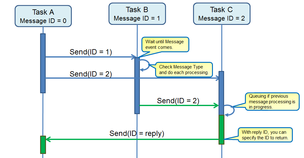
In addition, this message has Type, and it is judged by type and judged what kind of case the received data has instance or not, and if the instance is what is it.
| However, it is necessary to correctly implement the copy constructor for the class you want to send and receive. |
5.9.3.2. Message ID and Type
5.9.3.2.1. Message ID
Message ID is statically created according to the following How to write a Message Layout File configuration. For details of Configuration, please refer to that.
After confirming the ID, in the loop of the task,
MsgQueId id = XX; // Assign the created ID to a variable "id".
MsgQueBlock * que;
MsgPacket * msg;
err_t err = MsgLib::referMsgQueBlock(id, &que);
err = que->recv(TIME_FOREVER, &msg);By waiting for the Massage event, event-driven processing with Message ID = XX can be realized.
Conversely, when sending an event,
MsgQueId send_id = XX; // Assign ID that be sent to a variable "send_id".
MsgQueId ret_id = XX; // Assign ID that will return to a variable "self_id".
Object instance; // Class and Instance you want to send.
instance(); // Construction.
err_t err = MsgLib::send<Object>(send_id, MsgPriNormal, MSG_TYPE, ret_id, instance);In this way, assign the ID you want to send as send_id, the ID you wish to reply to ret_id, create an instance of the class (Object) you want to send, and send it with MsgLib::send.
the ID is created according to the application and explicitly used while designating the data path of transmission/reception.
5.9.3.2.2. Message Type
In order to extract the appropriate Instance from the received Message Packet, the Message Library uses the Message Type to determine what kind of object was sent. For this reason, Message Type is added to all Message Packet.
This Message Type is defined in "sdk/modules/include/memutils/message/message_type.h".
The Message Type takes the following data structure.
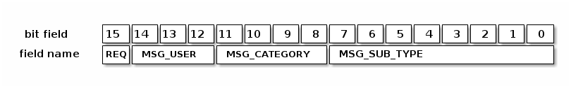
The description of each field is as follow.
| Field Name | Field | Description |
|---|---|---|
REQ |
[15] |
Indicates whether the message is a request or a response. 0 is the response, 1 is the request. |
MSG_USER |
[14-12] |
User information of the message. You can specify a system that uses messages with a value between 0 and 7. However, since 6 is reserved by AudioSubSystem and 7 by SensorSubSystem, it is actually possible to use values from 0 to 5. |
MSG_CATEGORY |
[11-8] |
Message category information. Categories can be specified with values from 0 to 15. |
MSG_SUB_TYPE |
[7-0] |
Message subtype information. You can specify a message type within a category with a value from 0 to 255. |
The defined ID is as follow.
Indicates the direction of the message.
| D15 | Description |
|---|---|
0 |
response |
1 |
request |
Specify the system using the message. The IDs of Audio and Sensor are currently reserved.
| D14 - D12 | Description |
|---|---|
0 - 5 |
reserved |
6 |
Audio Sub System |
7 |
Sensor Sub System |
Please freely define within each system.
For example, in the case of Audio,
"sdk/modules/include/audio/audio_message_types.h"
For Sensor,
"sdk/modules/include/sensing/sensor_message_types.h"
It is defined in.
Please freely define within each system.
For example, in the case of Audio,
"sdk/modules/audio/include/commmon/audio_interanl_message_types.h"
For Sensor,
"sdk/modules/include/sensing/sensor_message_types.h"
It is defined in.
| The message type can be operated even if the same value is defined when the ID is different, but for debuggability and modifiability, it is better to be made everything unique. |
We will extract Instance from Message Packet with the following implementation.
MsgQueBlock * que;
MsgPacket * msg;
err_t err = MsgLib::referMsgQueBlock(id, &que);
err = que->recv(TIME_FOREVER, &msg);
if (msg->getType() == MSG_TYPE) { // Check that the message type is as expected or not.
Object instance = msg->moveParam<Object>(); // get an instance of type Object from Message packet.
}5.9.3.3. APIs
The interface of "Message Library" is as follow. For details, see memutils_message.
5.9.3.3.1. Functions of the MsgLib class
static err_t MsgLib::initFirst(uint32_t num_pools, uint32_t top_drm)
uint32_t num_pools : Number of message segments (number of message types) uint32_t top_drm : Address of the management data area of the message library
ERR_OK: initialization succeeded ERR_STS: This function has been executed
Initialize the message library as a whole. Before using other APIs of this library, execute this function only once with a single CPU agreed in advance.
static err_t MsgLib::initPerCpu()
None
ERR_OK: initialization succeeded ERR_STS: MsgLib::initFirst() is not executed yet
Initialize the message library for each CPU. Initialization of various areas for each CPU and counting semaphores (OS environment only). All the CPUs using this library must wait to complete the execution of MsgLib::initFirst() and after that you need to execute this function. If MsgLib::initFirst() has not been executed, it is "debug_assert". If this API is executed again on the CPU that has already executed this API,it is "debug_assert".
static err_t MsgLib::finalize()
None
ERR_OK: initialization succeeded ERR_STS: MsgLib::initFirst() is not executed yet
Terminate the message library. Clear internal management information.
static bool MsgLib::isInitComplete(MsgQueId id)
MsgQueId id: Message queue ID
true: Initialized (CPU that owns the queue, initialization has been completed) false: Uninitialized
Get the message queue initialization status. If the message cube lock indicated by the argument id does not exist, it is "assert". If MsgLib::initFirst() has not been executed, it is "assert".
static err_t MsgLib::send(MsgQueId dest, MsgPri pri, MsgType type, MsgQueId reply) template<typename T> static err_t MsgLib::send(MsgQueId dest, MsgPri pri, MsgType type, MsgQueId reply, const T& param) static err_t send(MsgQueId dest, MsgPri pri, MsgType type, MsgQueId reply, const void* param, size_t param_size) static err_t MsgLib::sendIsr(MsgQueId dest, MsgPri pri, MsgType type, MsgQueId reply) template<typename T> static err_t MsgLib::sendIsr(MsgQueId dest, MsgPri pri, MsgType type, MsgQueId reply, const T& param) static err_t sendIsr(MsgQueId dest, MsgPri pri, MsgType type, MsgQueId reply, const void* param, size_t param_size)
MsgQueId dest: Destination message queue ID MsgPri pri: Message priority MsgType type: Value for identifying the message type MsgQueId reply: Reply destination message queue ID const T & param: Message parameters const void * param: address to message parameter size_t param_size: parameter size
ERR_OK: Send successful ERR_QUE_FULL: There is no space in the message queue
The message packet is stored in the queue indicated by the dest and pri arguments. send() is the task context, sendIsr() is used in the non-task context. When using parameters with sendIsr(), in order to minimize interrupt handling, as much as possible do not use class instances, minimize parameter size. If the size of the argument param is too large to be stored in the queue, it is "assert". There are no queues indicated by the dest and pri arguments, or the initialization is completed if not, it is "assert". When owning another CPU and designating a queue without spin lock sharing with its own CPU, it is "assert". If sendIsr() specifies a shared queue, it is "assert". This is to prevent spin lock waiting in non-task context.
static void MsgLib::notifyRecv(MsgQueId dest)
MsgQueId dest: notification destination message queue ID
None
It notifies reception of a message from another CPU or task. This function is assumed to be called from an communication interrupt handler. the If the lock indicated by the dest argument does not exist or the initialization has not been completed, It is "assert",
5.9.3.3.2. Functions of the MsgQueBlock class
static MsgQueBlock& MsgLib::referMsgQueBlock(MsgQueId id)
MsgQueId id: Message queue ID
Message cube lock reference
Get reference to message cube lock. If message cube lock indicated by argument id does not exist or initialization is not completed, it is "assert".
MsgPacket* MsgQueBlock::recv(uint32_t ms)
uint32_t ms: Reception wait time(ms) or TIME_POLLING or TIME_FOREVER
Non-NULL: Pointer to message packet in message queue NULL: Reception timeout
Waits to receive a message packet for the specified time. Unlike MsgLib::send(), simultaneous recv() to the same queue by multiple tasks is not supported. TIME_POLLING is defined as 0 and TIME_FOREVER is defined as -1. If the previously received message packet has not been destroyed by MsgQueBlock::pop(), It is "assert", If the message queue owns another CPU, It is "assert",
void MsgQueBlock::pop()
None
None
Remove the message packet from the message queue. If there is a parameter in the message packet, you must discard the parameters in advance by MsgPacket::moveParam() or MsgPacket::popParam(). Simultaneous pop() of the same queue by multiple tasks is not supported. If there is no discard target message packet, it is "assert". If the parameter length of the message packet to be discarded is other than 0, it is "assert". If the message queue owns another CPU, it is "assert".
uint16_t MsgQueBlock::getNumMsg(MsgPri pri) const
MsgPri pri: Message queue priority
Number of message packets
Get the number of message packets in the message queue. If the value of the arg argument is invalid, it is "assert".
uint16_t MsgQueBlock::getRest(MsgPri pri) const
MsgPri pri: Message queue priority
Number of message packets that can be stored
Get the number of message packets that can be stored in the message queue. Unused queues always return 0. If the argument pri is invalid, it is "assert".
5.9.3.3.3. Functions of the MsgPacket class
MsgType MsgPacket::getType() const
None
Message type ID
Get the type ID of the message packet.
MsgQueId MsgPacket::getReply() const
None
Reply queue ID
Get the reply queue ID of the message packet.
uint16_t MsgPacket::getParamSize() const
None
Message parameter length. 0 is returned when there is no parameter.
Get the parameter length of the message packet.
template <typename T> T MsgPacket :: moveParam()
None
Message parameters
Retrieve the parameter of the message packet (move). if "sizeof(T)! = MsgPacket::getParamSize()" is, it is "assert". This API is equivalent to the following processing. T param = MsgPacket::peekParam<T>(); /* Make a copy of the parameter with the left side unreferenced */ MsgPacket::popParam<T>(); /* Discard parameter */ return param; /* Return copy of parameter */ By calling this API, the message parameter length is changed to 0. Note that references to the message parameters and pointers are invalid.
template <typename T> const T& MsgPacket::peekParam() const template <typename T> const T& MsgPacket::peekParamOther() const
None
See const in message parameter
Get a reference to the parameter of the message packet. peekParam() is the same type as at the time of transmission, peekParamOther() is a different type (For example, the type of the header of the parameter). peekParam() is assert, if "sizeof(T)! = MsgPacket::getParamSize()". peekParamOther() is assert, if "sizeof(T) > MsgPacket::getParamSize()". If you get the return value of these APIs as non-referenced, you can get a copy of the parameters.
template <typename T> void MsgPacket::popParam() void MsgPacket::popParamNoDestruct()
None
None
Discards the parameter of the message packet. popParam() calls the destructor of the parameter. Since popParamNoDestruct() does not call the destructor, the destructor it can only be used for message packets that do not exist. Unless there is a special reason, use popParam(). popParam()is assert, if "sizeof(T) != MsgPacket::getParamSize(). By calling these APIs, the message parameter length is changed to 0. Note that references to the message parameters and pointers are invalid.
5.9.3.4. Configurations and Generate
Here we explain how to write and create the "Message Library" Layout file.
Layout information is described in Python in "msgq_layout.conf" (name of the file can change) With the tool "msgq_layout.py", two headers in C ++ language, "msgq_id.h" "msgq_pool.h" will be generated. Users can use "Message Library" by including this header.
5.9.3.4.1. How to write a Message Layout File
"msgq_layout.conf" defines the user constants of "Message Library", defines the message queue pool, specifies the debug value, and checks the message parameters. The explanation of each is shown below.
If you want to add user’s unique definitions, you would be recommand to define that starts with "U_" in the Message Layout file.
Example of writing user-defined constants
# User-defined constants must be the names of uppercase letters and numbers beginning with "U_" # If defined with a name beginning with "U_MSGQ_", it is also output as a define macro in msgq_id.h U_HEADER_SIZE = 8 # Message packet header size
You can define a message queue pool using user defined constants.
Description example of message queue pool definition
U_MSG_SIZE = 16 U_MSG_NUM = 8 MsgQuePool = [ # ID, n_size n_num h_size h_nums ["MSGQ_USER_APP", U_MSG_SIZE, U_MSG_NUM, 0, 0], ["MSGQ_DSP_CMD", 256, 10, U_MSG_SIZE, U_MSG_NUM], None # end of user definition # end of MsgQuePool
The explanation of each parameter is as follow.
| Parameter | Description |
|---|---|
ID |
Specify the name of the message queue pool ID as a character string beginning with "MSGQ_". "MSGQ_NULL", "MSGQ_TOP", "MSGQ_END" are reserved and therefore prohibited. |
n_size |
Number of bytes of each element of the normal priority queue (8 or more and 512 or less). Specify fixed header length (8 bytes) + parameter length as a multiple of 4. |
n_num |
Number of elements of normal priority queue (1 or more and 16384 or less). |
h_size |
Number of bytes (0 or 8 to 512 inclusive) for each element of the high priority queue. Please specify 0 when not in use. |
h_num |
Number of elements in the high priority queue (0 or 1 to 16384 or less). Please specify 0 when not in use. |
|
Although there is also a designation of debugging value and checking of message parameters, please do not use it. MsgFillValueAfterPop = 0x00 MsgParamTypeMatchCheck = false |
5.9.3.4.2. How To Generate
The way to create a Layout file using "msgq_layout.py" is as follow.
- Usage
python3 msgq_layout.conf [start_addr] [size] [id_header] [pool_header]
- Example
python3 msgq_layout.conf 0x000fe000 0x1000 msgq_id.h msgq_pool.h
The explanation of each argument of "msgq_layout.py" is as follow.
| Parameter | Description |
|---|---|
msgq_layout.conf |
Message queue layout definition file |
start_addr |
Address of message area. If this argument is nothing, then start_addr is set from "mem_layout.h". |
size |
Area size in bytes. If this argument is nothing, then size is set from "mem_layout.h". |
id_header |
File to which message queue ID macro is output. A "msgq_id.h" is generated without this argument. |
pool_header |
File in which definition of message queue pool is output. A "msgq_pool.h" is generated without this argument. |
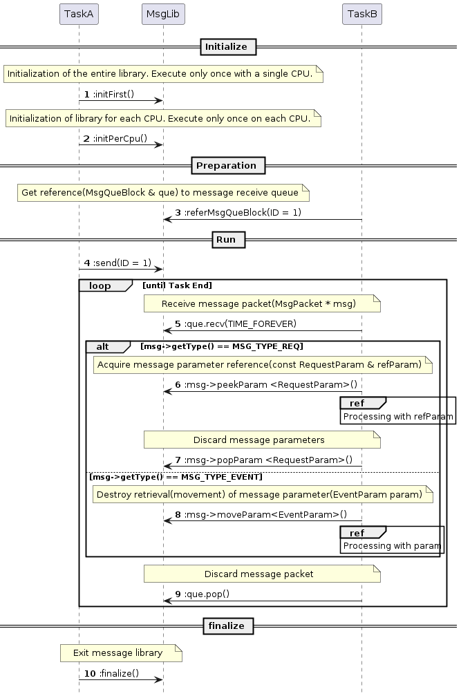
5.9.4. Simple FIFO
5.9.4.1. General
Simple FIFO This library supports one-writer and one-reader access without any exclusive control. Some exclusive access control is required to support multi-writer/reader outside of this library.
5.9.4.2. APIs
For details, refer to Doxygen. A list of APIs is as follow.
-
Simple FIFO API List
API name |
Description |
CMN_SimpleFifoInitialize |
Initialization of Simple FIFO. Sets the memory area used for FIFO. |
CMN_SimpleFifoOffer |
Push data to the FIFO. Copy processing uses memcpy(). |
CMN_SimpleFifoOfferWithSpecificCopier |
Push data to the FIFO. Copy processing is prepared by the user side. We are assuming copy using DMA. |
CMN_SimpleFifoOfferContinuous |
Push data to the FIFO. It copies to the continuous area by the specified size. If there is no contiguous area for the specified size, push is not performed. Copy processing uses memcpy(). |
CMN_SimpleFifoOfferContinuousWithSpecificCopier |
Push data to the FIFO. It copies to the continuous area by the specified size. If there is no contiguous area for the specified size, push is not performed. Copy processing is prepared by the user side. We are assuming copy using DMA. |
CMN_SimpleFifoPoll |
Pops the data from the FIFO. Pop data will be deleted from the FIFO. Copy processing uses memcpy(). |
CMN_SimpleFifoPollWithSpecificCopier |
Pops the data from the FIFO. Pop data will be deleted from the FIFO. Copy processing is prepared by the user side. We are assuming copy using DMA. |
CMN_SimpleFifoPeekWithOffset |
Acquires address information of specified size data from Offset specified from the beginning of the FIFO. It is used when you want to refer to the FIFO data without deleting it. |
CMN_SimpleFifoPeek |
Acquires address information of data of the specified size from the beginning of the FIFO. It is used when you want to refer to the FIFO data without deleting it. ** |
CMN_SimpleFifoClear |
Clear FIFO Read / Write pointer to empty state. |
CMN_SimpleFifoGetVacantSize |
Get the free size of the FIFO. |
CMN_SimpleFifoGetOccupiedSize |
Get the FIFO usage size. |
CMN_SimpleFifoGetExtInfo |
Acquires the extended information of the FIFO set by CMN_SimpleFifoInitialize(). |
CMN_SimpleFifoGetDataSizeOfPeekHandle |
Get the number of elements of address information acquired by CMN_SimpleFifoPeek(). |
CMN_SimpleFifoCopyFromPeekHandle |
Acquires data from address information acquired by CMN_SimpleFifoPeek(). Copy processing uses memcpy(). |
CMN_SimpleFifoCopyFromPeekHandleWithSpecificCopier |
Get data from address information obtained by CMN_SimpleFifoPeek(). Copy processing is prepared by the user side. We are assuming copy using DMA. |
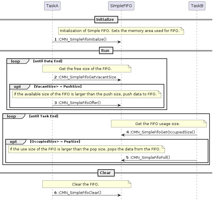
5.10. Power Management
5.10.1. Overview
Power Management is a module to achieve power saving which is a characteristic feature of the Spresense SDK. It manages the power domain and clock in the CXD5602 and supports various sleep modes.
5.10.2. Power State
The Spresense SDK supports three sleep modes in order to save power: Deep Sleep, Cold Sleep, and Hot Sleep.
Deep Sleep-
The CXD5602 is in a state where all power domains are turned off and only the CXD5247 PMIC (Power Management IC) is turned on. In this state, the CXD5247 has the lowest power consumption.
Cold Sleep-
In this state, the necessary minimum power domains are turned on in the CXD5602. Compared to
Deep Sleep, this state can be awakened by triggers of various factors, such as an alarm timer, USB insertion/removal, or the changes of the GPIO signal. Hot Sleep-
This state is entered after the OS has been idle for a while without being interrupted. Since SRAM state is retained during this state, it is not necessary to reload the program from SPI-Flash, and it can be awakened at high speed.
In the current SDK version, Hot Sleep is not supported.
|
5.10.2.1. Power State Transition
The power state transition diagram is shown below.
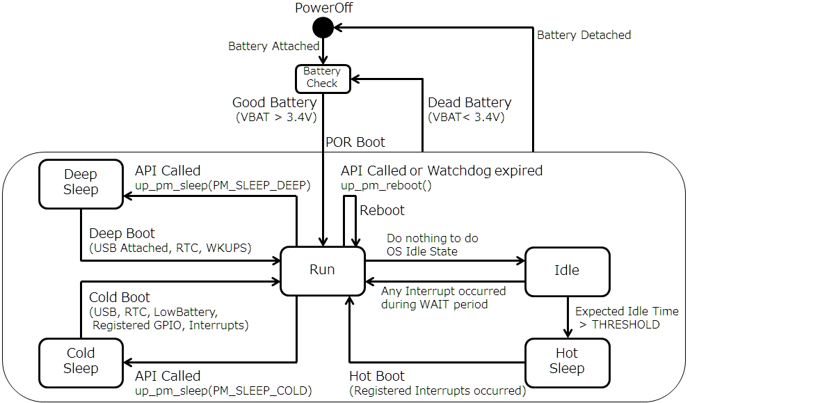
| State | Description |
|---|---|
PowerOff |
No power supply as battery detached. |
Battery Check |
Monitors the voltage level of the power supply. When the power supply is 3.4V or higher, the CXD5602 boots and enters the run state. |
Run |
Normal running state. |
Idle |
The OS is idle and waits for an interrupt (WFI). |
Hot Sleep |
When the OS is in idle state and stays idle for longer than the threshold time, this state is entered. During Hot Sleep state, SRAM data is retained. |
Cold Sleep |
Only the necessary minimum power supply of CXD5602 is turned on, all other power supplies such as SRAM are turned off. |
Deep Sleep |
The CXD5602 is turned off and only the CXD5247 PMIC (Power Management IC) is turned ON. |
The Spresense SDK supports the following states:
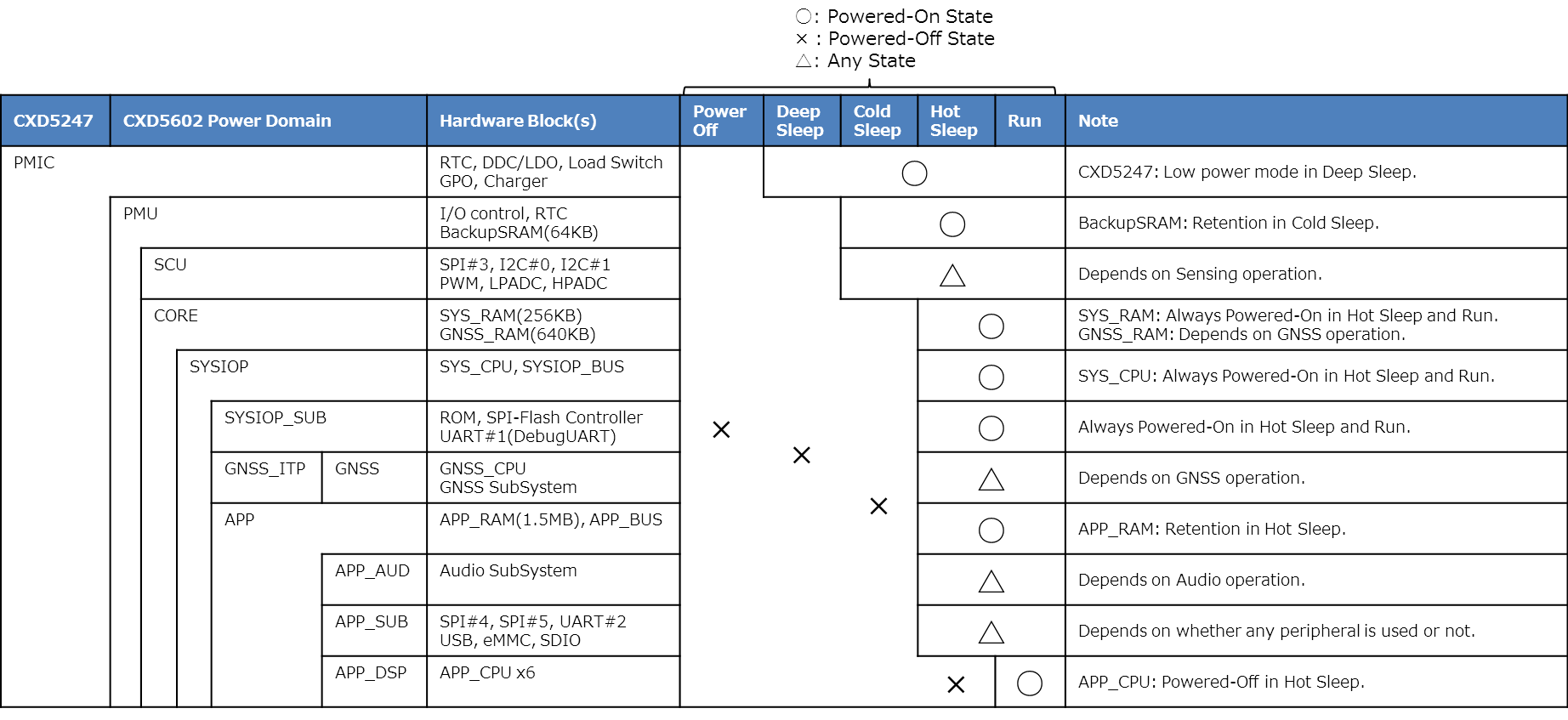
5.10.3. Power State Control API
The Spresense SDK has the cause of boot-up or wake-up (called as boot cause) and the mask for controlling whether to enable or disable the boot cause (called as boot mask).
- boot cause
-
Indicates the cause of boot-up or wake-up from the various sleep modes.
- boot mask
-
Indicates the mask to be enabled or disabled by the boot cause.
boot cause and boot mask have the common bit flag structure, and each factor is represented by one bit. If 1 is set in the corresponding bit of boot mask, it will be enabled as the wake-up factor and if set to 0 it will be disabled. When in Sleep state, it wakes up from Sleep state when an event of wake-up factor allowed by boot mask occurs. At that time, the boot cause is reflected in boot cause.
The boot cause and boot mask are defined as follows.
-
Boot Type is POR (Power-On-Reset), Reboot, the wake-up from
Deep SleeporCold Sleepstate. -
Maskable is enabled as the boot cause only for Yes. No is disabled as the boot cause.
| boot cause / boot mask | Boot Type | Maskable | Description |
|---|---|---|---|
PM_BOOT_POR_NORMAL |
POR Boot |
No |
Battery or power turned on |
PM_BOOT_POR_DEADBATT |
POR Boot |
No |
Battery or power supply is 3.4 V or higher |
PM_BOOT_WDT_REBOOT |
Reboot |
No |
Rebooted by system watchdog |
PM_BOOT_WDT_RESET |
Reboot |
No |
Reset by a CXD5602 watchdog |
PM_BOOT_DEEP_WKUPL |
Deep Boot |
Yes |
Detected the WKUPL signal(*2) |
PM_BOOT_DEEP_WKUPS |
Deep Boot |
Yes (*1) |
Detected the WKUPS signal(*2) |
PM_BOOT_DEEP_RTC |
Deep Boot |
Yes (*1) |
Expired RTC Alarm |
PM_BOOT_DEEP_USB_ATTACH |
Deep Boot |
No |
Connected USB(*2) |
PM_BOOT_DEEP_OTHERS |
Deep Boot |
No |
Not used |
PM_BOOT_COLD_SCU_INT |
Cold Boot |
Yes |
Detected SCU interrupt |
PM_BOOT_COLD_RTC |
Cold Boot |
Yes |
Expired RTC Alarm |
PM_BOOT_COLD_RTC_ALM0 |
Cold Boot |
Yes |
Expired RTC Alarm0 (This is used by SDK) |
PM_BOOT_COLD_RTC_ALM1 |
Cold Boot |
Yes |
Expired RTC Alarm1 (Not used) |
PM_BOOT_COLD_RTC_ALM2 |
Cold Boot |
Yes |
Expired RTC Alarm2 (Not used) |
PM_BOOT_COLD_RTC_ALMERR |
Cold Boot |
Yes |
Expired RTC Alarm Error (Not used) |
PM_BOOT_COLD_GPIO |
Cold Boot |
Yes |
Detected GPIO interrupt |
PM_BOOT_COLD_SEN_INT |
Cold Boot |
Yes |
Detected sensor interrupt (SEN_INT) |
PM_BOOT_COLD_PMIC_INT |
Cold Boot |
Yes |
Detected interrupt from PMIC (CXD5247) |
PM_BOOT_COLD_USB_DETACH |
Cold Boot |
Yes |
Disconnected USB(*2) |
PM_BOOT_COLD_USB_ATTACH |
Cold Boot |
Yes |
Connected USB(*2) |
(*1) Both PM_BOOT_DEEP_WKUPS and PM_BOOT_DEEP_RTC can not be disabled.
(*2) Not supported on the Spresense board.
Regarding the power state control, the following Power Management APIs are provided:
-
Get the boot cause.
-
Get the boot mask.
-
Enable / disable the boot cause.
-
Enter the sleep mode.
-
Reboot.
5.10.3.1. up_pm_get_bootcause()
- Function Prototype
uint32_t up_pm_get_bootcause(void);- Description
-
-
Returns the boot cause.
-
5.10.3.2. up_pm_get_bootmask()
- Function Prototype
uint32_t up_pm_get_bootmask(void);- Description
-
-
Returns the boot mask.
-
Enables all boot causes by default.
-
Resets the boot mask at Deep Sleep or Power-On-Reset. The boot mask is kept during hot sleep and cold sleep.
-
-
5.10.3.3. up_pm_set_bootmask()
- Function Prototype
uint32_t up_pm_set_bootmask(uint32_t mask);- Description
-
-
Enables the boot cause specified in the argument.
-
Returns the updated boot mask.
-
5.10.3.4. up_pm_clr_bootmask()
- Function Prototype
uint32_t up_pm_clr_bootmask(uint32_t mask);- Description
-
-
Disables the boot cause specified in the argument.
-
Returns the updated boot mask.
-
- Example
-
#include <arch/chip/pm.h> uint32_t bootmask; bootmask = up_pm_get_bootmask(); // Get the current bootmask printf("bootmask=0x%08x\n", bootmask); bootmask = up_pm_clr_bootmask(PM_BOOT_COLD_USB_DETACH); // Disable wakeup by USB detached printf("bootmask=0x%08x\n", bootmask); // Display the updated bootmask
5.10.3.5. up_pm_sleep()
- Function Prototype
int up_pm_sleep(enum pm_sleepmode_e mode);- Description
-
-
Enters the sleep mode specified in the argument.
-
Doesn’t come back from the function call.
-
- Arguments
-
Argument mode Description PM_SLEEP_DEEP
Enter Deep Sleep
PM_SLEEP_COLD
Enter Cold Sleep
By calling up_pm_sleep(), the OS enters Sleep mode as a single CXD5602 chip.
To control Sleep mode with the board instead of the chip,
the function board_power_off() needs to be implemented in the board specific code of BSP.
The Sleep transition API implemented in the BSP is shown below.
This can also be controlled from the poweroff command in NuttShell.
- Function Prototype
int board_power_off(int status)- Arguments
-
Argument status Description NuttShell command BOARD_POWEROFF_DEEP
Enter Deep Sleep
poweroff
BOARD_POWEROFF_COLD
Enter Cold Sleep
poweroff 1
5.10.3.6. up_pm_reboot()
- Function Prototype
int up_pm_reboot(void);- Description
-
-
Reboots the system.
-
Doesn’t come back from the function call.
-
If you want to control the reboot with board, you can implement board_reset() function in board specific code of BSP.
- Function Prototype
int board_reset(int status);The board_reset() can also be controlled from the reboot command on NuttShell.
5.10.4. Sleep Mode
5.10.4.1. Deep Sleep
5.10.4.1.1. Features:
-
The CXD5602 is turned off.
-
The CXD5247 enters
Sleep mode, and the Core voltage and I/O voltage supplied to the CXD5602 are turned off.-
If your system has an RTC XTAL, it retains the RTC time.
-
The GPO value of CXD5247 switch is retained during
Deep Sleep.-
If the GPO is not needed to be turned on during
Deep Sleep, it is recommended to turn it off before enteringDeep Sleepto minimize power consumption.
-
-
CXD5247 Load Switch is turned OFF.
-
Make sure that current does not leak from the peripheral device to the CXD5602 since the I/O of the CXD5602 is turned OFF.
-
5.10.4.1.2. Power Consumption
-
The power consumption of the battery is about several uA at the battery end. However, this value depends on board design. Since the CXD5602 is powered off, design the circuit board carefully so that there is no leakage current from the peripheral device to the CXD5602.
| About the power consumption during sleeping, when the SD card is inserted on the Spresense extension board, the current consumption increases by about 5 mA for the power supply to the SD card. |
5.10.4.1.3. Sleep Conditions
-
Call
up_pm_sleep(PM_SLEEP_DEEP)orboard_poweroff(BOARD_POWEROFF_DEEP). -
Assert the
WKUPLsignal for more than three seconds.
The Spresense board doesn’t have the WKUPL terminal, therefore transition to Deep Sleep by the signal can not be used.
|
5.10.4.1.4. Wakeup Conditions
When any wake-up condition occurs, the program will be loaded from SPI-Flash, so it takes about the same time as starting by Power-On-Reset.
-
PM_BOOT_DEEP_WKUPL: Assert theWKUPLsignal for more than three seconds. -
PM_BOOT_DEEP_WKUPS: Assert theWKUPSsignal. -
PM_BOOT_DEEP_RTC: A RTC alarm expired. -
PM_BOOT_DEEP_USB_ATTACH: Connected the USB port to a power source.-
Normally, when the USB cable is connected, you can not enter the Deep Sleep state. However, if you set CONFIG_BOARD_USB_DISABLE_IN_DEEP_SLEEPING=y, you can disable the USB function and enter the Deep Sleep state. At this time, it can not wake up with a USB connection as a trigger.
-
The Spresense board doesn’t have the WKUPL and WKUPS terminals, therefore wake-up from Deep Sleep by the signals can not be used.
|
5.10.4.2. Cold Sleep
5.10.4.2.1. Features:
-
Only the PMU power domain in the CXD5602 is ON.
-
CXD5602 I/O pin is activated.
-
Backup SRAM are retained.
-
-
CXD5247 is the normal running state.
-
If your system has an RTC XTAL, it retains the RTC time.
-
The GPO signal is retained.
-
The Load Switch signal is retained.
-
5.10.4.2.2. Power Consumption
-
The power consumption of the battery is approximately several hundred uA at the battery end. This current value depends on board design.
| About the power consumption during sleeping, when the SD card is inserted on the Spresense extension board, the current consumption increases by about 5 mA for the power supply to the SD card. |
5.10.4.2.3. Sleep Conditions
-
Call
up_pm_sleep(PM_SLEEP_COLD)orboard_poweroff(BOARD_POWEROFF_COLD).
5.10.4.2.4. Wakeup Conditions
When any wake-up condition occurs, the program will be loaded from SPI-Flash, so it takes about the same time as starting by Power-On-Reset.
-
PM_BOOT_COLD_SCU_INT: A SCU interrupt is asserted. -
PM_BOOT_COLD_SEN_INT: A sensor interrupt is asserted. -
PM_BOOT_COLD_PMIC_INT: A interrupt from CXD5247 is asserted.-
WKUPS signal is asserted.
-
Low Battery notification is asserted.
-
-
PM_BOOT_COLD_GPIO: A GPIO interrupt is asserted. -
PM_BOOT_COLD_RTC_ALM0: A RTC Alarm expired. -
PM_BOOT_COLD_USB_ATTACH: Connected the USB port. -
PM_BOOT_COLD_USB_DETACH: Disconnected the USB port.
The Spresense board does not support wake-up from Cold Sleep by attached/detached USB.
|
5.10.4.3. Hot Sleep
In the current SDK version, Hot Sleep is not supported.
|
5.10.4.3.1. Features
-
The CXD5602 is almost equal to the normal running state, but the CPU application on which NuttX is running, is turned off.
-
However, SRAM is retained during
Hot Sleep.
-
-
CXD5247 is in the normal running state.
5.10.4.3.2. Power Consumption
-
The power consumption of the battery can be lowered to at most a few hundred uA at the battery end, but it depends strongly on what is operating as an application.
5.10.4.3.3. Sleep Conditions
-
If
CONFIG_CXD56_HOT_SLEEP=y,Hot Sleepis enabled.-
With the CONFIG parameter below, you can change the condition to transition to
Hot Sleepstate.-
CONFIG_CXD56_HOT_SLEEP_WAIT_COUNT(milliseconds) -
CONFIG_CXD56_HOT_SLEEP_THRESHOLD(milliseconds)
-
-
Acquiring and releasing wakelock.
-
Hot Sleepcontrol is performed with the wakelock mechanism to be described later. As long as at least one wakelock is acquired, transition toHot Sleepis prohibited.
-
-
Power Manager transits to the Hot Sleep state with the following algorithm:
-
When the NuttX OS is idle,
Power Managercounts the time to stay idle.-
If any interrupt occurs, the system leaves the idle state and the counter is reset.
-
-
If the counter exceeds the value defined by
CONFIG_CXD56_HOT_SLEEP_WAIT_COUNT,Power Managerwill calculate by predicting the following idle time. -
If this predicted idle time >
CONFIG_CXD56_HOT_SLEEP_THRESHOLDhas been exceeded, the system will enter theHot Sleepstate.-
When any wakelock is acquired, the system is prohibited from entering the
Hot Sleepstate.
-
5.10.4.3.4. Wakeup Conditions
-
Any interrupt to NuttX CPU is asserted.
-
UART1 Rx interrupt.
-
UART2 Rx interrupt.
-
SCU (Sensor Control Unit) Watermark interrupt.
-
USB VBUS (Connected) interrupt.
-
USB VBUS Negative (Disconnected) interrupt.
-
PMIC (Low Battery Notification or WKUPS) interrupt.
-
Any GPIO interrupt(s) that was registered and used before entering Hot Sleep.
-
Inter-CPU communication from other CPUs to NuttX CPU.
-
NuttX OS timer event interrupt.
5.10.5. Power Saving Control
The SDK provides the following power-saving control features:
-
A CPU working frequency control.
-
A CPU power down control.
5.10.5.1. CPU Working Frequency Control
The SDK provides the following frequency states:
| Mode | CPU Clock | CXD5602 Core Voltage |
|---|---|---|
HV (High Voltage) Mode |
PLL 156MHz |
1.0 V |
LV (Low Voltage) Mode |
PLL 32MHz |
0.7 V |
RCOSC Mode |
RCOSC approximately 8MHz |
0.7 V |
By default, the SDK uses the high voltage mode and cannot transition to another mode. To release the CPU frequency lock, apply the following configuration settings:
When the dynamic clock control is disabled, it always operates in HV mode. To enable the power saving function by dynamic clock control, please set the following configuration.
[CXD56xx Configuration]
[Power Management]
[Dynamic clock control] <= Y
When Dynamic clock control is enabled, the system will start clocking in HV mode and then clock down to RCOSC mode. In steady state, it operates in RCOSC mode.
If the system requires high performance temporarily, it is possible to change the clock dynamically using the Frequency Lock mechanism.
Although the operating clock rises in the order of RCOSC mode, LV mode, HV mode, but the power consumption also increases accordingly. The frequency lock mechanism acquires LV lock when switching to LV mode, and HV lock when switching to HV mode. Releasing the acquired lock returns to the original clock state. As long as any one of the clients acquires a lock of the higher clock mode, the system operates in a higher clock mode. As an example, if both LV lock and HV lock have been acquired, it will be in HV mode. When the HV lock is released, it switches to LV mode, the next higher clock mode. Then, when the LV lock is also released, it returns to the RCOSC mode.
-
Acquire HV lock.
struct pm_cpu_freqlock_s lock; lock.flag = PM_CPUFREQLOCK_FLAG_HV; up_pm_acquire_freqlock(&lock); -
Release HV lock.
up_pm_release_freqlock(&lock); -
Acquire LV lock.
struct pm_cpu_freqlock_s lock; lock.flag = PM_CPUFREQLOCK_FLAG_LV; up_pm_acquire_freqlock(&lock); -
Release LV lock
up_pm_release_freqlock(&lock);
Although the system clock is dynamically changed according to the acquire/release of HV and LV locks, there may be periods when you want to avoid changing the clock, for example, during SPI transfer. By using the PM_CPUFREQLOCK_FLAG_HOLD flag, it is possible to prevent the system clock from being changed during the period when the hold flag is locked.
| Do not lock the duplicated PM_CPUFREQLOCK_FLAG_HOLD flag from a thread. Since the PM_CPUFREQLOCK_FLAG_HOLD flag is implemented using semaphores, the duplicated locks from a thread, up_pm_acquire_freqlock() is called twice, will cause the thread to deadlock. |
-
Acquire HOLD lock.
struct pm_cpu_freqlock_s lock; lock.flag = PM_CPUFREQLOCK_FLAG_HOLD; up_pm_acquire_freqlock(&lock); -
Release HOLD lock
up_pm_release_freqlock(&lock);
5.10.5.2. CPU power down control
The SDK provides a function to automatically transition to Hot Sleep when the application CPU is in the idle state.
In the current SDK version, Hot Sleep is not supported.
|
By default, the Hot Sleep function is disabled. The following settings are required to enable this function:
[CXD56xx Configuration]
[Power Management]
[Hot Sleep] <= Y
[Hot Sleep wait counter] <= 20
[Hot Sleep threshold] <= 1000
[Enable GNSS Hot Sleep] <= Y
When CONFIG_CXD56_HOT_SLEEP=y, it automatically enters the Hot Sleep state in the OS idle state.
By setting CONFIG_CXD56_GNSS_HOT_SLEEP=y, it enables the Hot Sleep function of the GNSS CPU.
In the idle state, it automatically enters the Hot Sleep state, but it can suppress the transition to the Hot Sleep state by the wakelock mechanism.
-
Acquire wakelock.
struct pm_cpu_wakelock_s lock; lock.count = 0; up_pm_acquire_wakelock(&lock); -
Release wakelock.
up_pm_release_wakelock(&lock);
5.11. Sensor Fusion Framework
5.11.1. General
CXD5602 has a function to constantly sensing with low power consumption. Then, the sensor fusion function can be supported by multiple cores and memory.
SDK provides a framework for easily supporting these.
The sensor fusion framework consists of "Sensor Manager" and "Sensor Client" for each sensor.
-
"Sensor Manager" controls multiple "Sensor Client" based on the Publish-Subscribe Architecture and delivers Published Sensor Data from "Sensor Manager".
-
"Sensor Client" consists on of "Physical Sensor", "Logical sensor" and "Sensor Application". "Physical Sensor" controls drivers that control various "Sensor Devices". "Logical Sensor" supports a highly functional sensor by fusing data from each "Sensor Device". "Sensor Application" is required for Application to receive data.
The Architecture diagram of Sensor Framework is as follow.
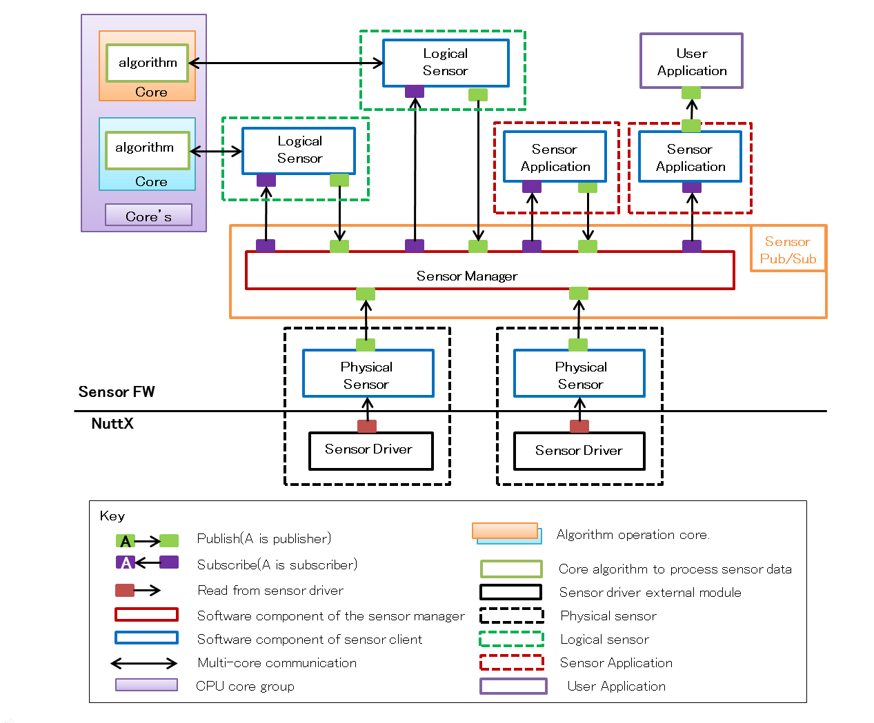
5.11.2. Sensor Manager
"Sensor Manager" registers and manages multiple "Sensor Client" and properly distributes sensor data.
5.11.2.1. General
"Sensor Client" registered in "Sensor Manager" send the acquired data to "Sensor Manager". "Sensor Manager" delivers the received data to "Sensor Client" that requesting subscribe.
In addition, it provides a framework that can power off the "Sensor Client" which is not subscribed.
5.11.2.2. APIs
"Sensor Manager" provides the following APIs. The "Sensor Manager" interface is controllable to issue commands in data format called packets. Register, delete, send and receive "Sensor Client".
| APIs | Description | Corresponding API | Corresponding packet |
|---|---|---|---|
Register |
Resister a Sensor Client to Sensor Manager as subscriber. |
sensor_command_register_t |
|
Release |
Unregister the Sensor Client from Sensor Manager. |
sensor_command_release_t |
|
SendData |
Sender function to Sensor Manager without MemHandle. |
sensor_command_data_t |
|
SendData(MH) |
Sender function to Sensor Manager with MemHandle. |
sensor_command_data_mh_t |
|
SendSetPower |
Set power status of sensors. |
sensor_command_power_t |
5.11.2.3. Sequence
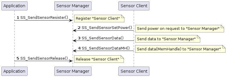
| For MemHandle please refer to Memory Manager Library. |
5.11.3. Logical Sensors
5.11.3.1. General
"Logical sensor" is composed of "Sensor Client" for creating sensor data obtained from various physical sensors based on some kind of signal processing algorithm, to create highly functional sensor data.
There are several ways of implementing allocation of actual algorithms as follow.
-
Implement it as a task on NuttX.
-
Implement on the DSP using the asmp framework.
-
Implement using the encrypted DSP provided by each vendor.
5.11.3.1.1. A logical sensor task on NuttX
Implement as module or task on NuttX.
Especially, in the case of processing which is not heavy or it is not frequent, this type of implementation can be used which will not consume memory and CPU resources.
| Contents | Sample provider |
|---|---|
Barometer |
From sensor vender |
TAP Gesture (Tapping Detector) |
From SDK |
5.11.3.1.2. A logical sensor on DSP by asmp
In the case where the user independently creates an algorithm of "Logical Sensor" and needs to offload the processing to the DSP side (for example, heavy processing), it is implemented on the DSP side using the ASMP framework.
In such case, "Logical Sensor" can be supported by multicore processing by implementing "Logical Sensor" with supervisor task and sending processing request from the supervisor task to the Worker task on the DSP for processing.
| Contents | Sample provider |
|---|---|
"" |
From SDK |
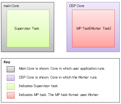
| For ASMP framework please refer to ASMP Framework. |
A logical sensor on DSP with encryption
Each solution vendor provides various logical sensor algorithms. In that case, each vendor can provide the function based on each contract. without disclosing the code.
In this case, it can be supported by loading the build and encrypted binaries on the ASMP framework. Encrypted DSP is provided by each vendor.
| Contents | Sample provider |
|---|---|
AESM (Activity Engine and Step Meter) |
From SDK |
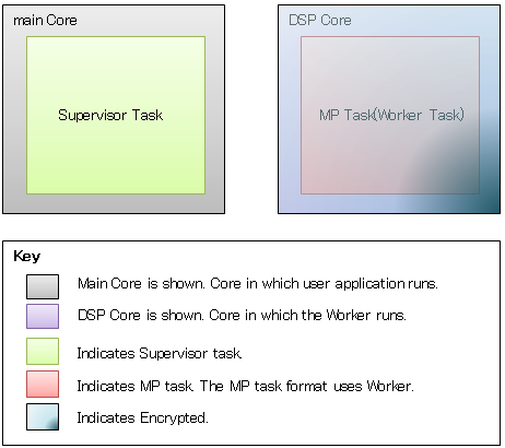
5.11.4. Logical Sensor API
Each Logical sensor provides the following APIs.
| APIs | Description |
|---|---|
Create |
Create a class instance to communicate with workers. |
Open |
Load library and boot up as worker task. |
Write |
Send data to worker task. |
Close |
Destroy worker task. |
These requests are defined as the following events and are used for sending and receiving with the Worker task on the DSP.
For details, refer to each supervisor.
| Event | Description |
|---|---|
Init |
Initialization event. |
Exec |
Execution event. |
Flush |
Terminal event. |
5.11.6. Step Counter
The configuration diagram of "Step Counter" is shown below.
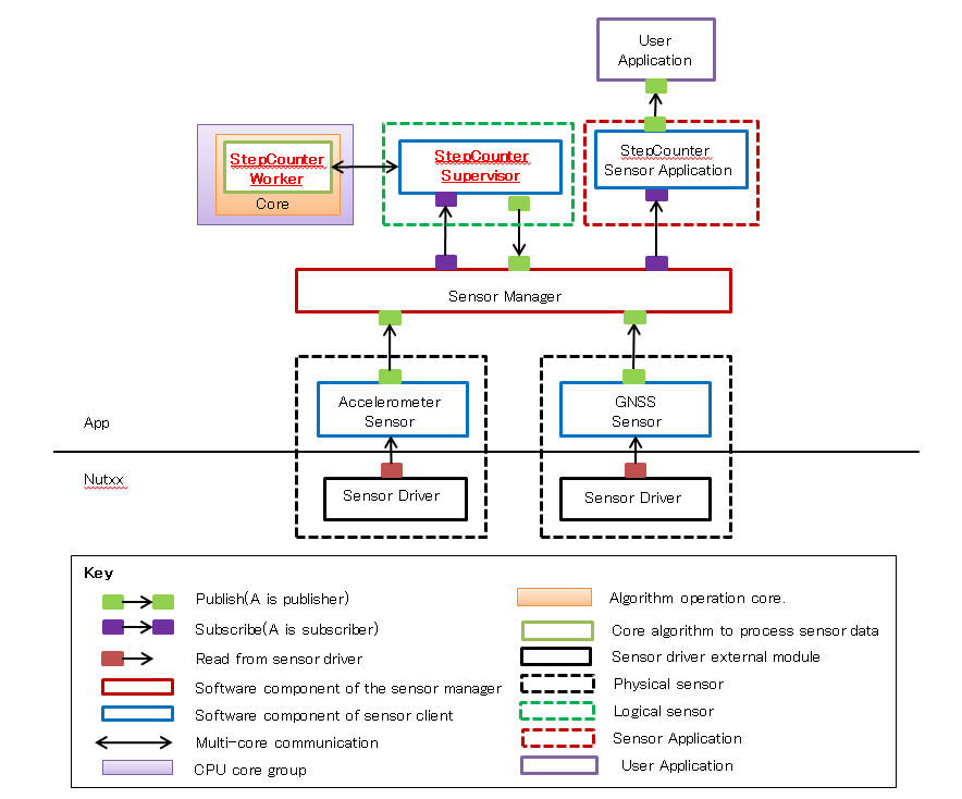
5.11.6.1. Supervisor
Supervisor is a framework for "Logical Sensor". It provides several APIs for controlling the Worker on the Supervisor’s DSP.
5.11.6.1.1. APIs
"Step Counter" provides the following 5 APIs.
| APIs | Description | Corresponding API |
|---|---|---|
Create |
Create StepCounterClass instance. |
|
Open |
Load StepCounter library and boot up as worker task. |
|
Write |
Send data to StepCounter worker task. |
|
Close |
Destroy StepCounter worker task. |
|
Set |
Set setting to StepCounter library . |
5.11.6.1.2. Data format for Step Counter
"Step Counter" requires "Accelerometer" data in the format specified as follow.
"Application" will send these data to the worker with Write API.
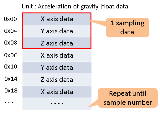
5.11.6.1.3. Result of sensing
"Step Counter" outputs the following pedometer information every 1 second. These information are stored in StepCounterStepInfo.
| Information | Unit | Note |
|---|---|---|
Tempo |
Hz |
Take a value of 1, 2, 3 Hz. Even when it is in the stopped state, it is 1 Hz or more. |
Stride length |
cm |
It becomes a fixed value in walking and running respectively. |
Speed |
m/s |
|
Distance |
m |
|
Step count |
- |
|
Behavior recognition |
- |
It indicates stopping/walking/running condition. |
5.11.6.2. How to use
5.11.6.2.1. Preparation
It controls "Step Counter" with "Sensor Manager" framework designed to control multiple "Sensor Client".
Therefore, in order to control "Step Counter", you need to enable "Sensor Manager" in advance.
To enable "Sensor Manager" you need to call SS_ActivateSensorSubSystem(MsgQueId, api_response_callback_t) .
MsgQueId must specify the MsgQueID defined in Message Library Configuration.
api_response_callback_t specifies a callback function for asynchronous notification. If NULL is specified, notification is not performed.
static void sensor_manager_api_response(unsigned int code,
unsigned int ercd,
unsigned int self)
{
...
}
SS_ActivateSensorSubSystem(MSGQ_SEN_MGR, sensor_manager_api_response);After "Sensor Manager" is activated, in order for "Step Counter" to know the sensing result of "Accelerometer", "Step Counter" registers "Accelerometer" as "Sensor Client" which request "Subscribe".
Then, specify a callback function that processes "Subscribe". In the callback function, call StepCounterWrite.
Also, in order for "Application" to know the sensing result of "Step Counter", "Application" registers "Step Counter" as "Sensor Client" which request "Subscribe".
Then, specify a callback function that processes "Subscribe". In the callback function, do processing to display or notify the result.
bool step_counter_receive_data(sensor_command_data_mh_t& data)
{
StepCounterWrite(sp_step_counter_ins, &data);
return true;
}
bool step_counter_recieve_result(sensor_command_data_mh_t& data)
{
bool ret = true;
FAR SensorCmdStepCounter *result_data =
reinterpret_cast<SensorCmdStepCounter *>(data.mh.getVa());
if (SensorOK == result_data->result.exec_result)
{
if (result_data->exec_cmd.cmd_type ==
STEP_COUNTER_CMD_UPDATE_ACCELERATION)
{
...
}
}
return ret;
}
sensor_command_register_t reg;
reg.header.code = ResisterClient;
reg.self = stepcounterID;
reg.subscriptions = (0x01 << accelID);
reg.callback = NULL;
reg.callback_mh = &step_counter_receive_data;
SS_SendSensorResister(®);
reg.header.code = ResisterClient;
reg.self = app0ID;
reg.subscriptions = (0x01 << stepcounterID);
reg.callback = NULL;
reg.callback_mh = &step_counter_recieve_result;
SS_SendSensorResister(®);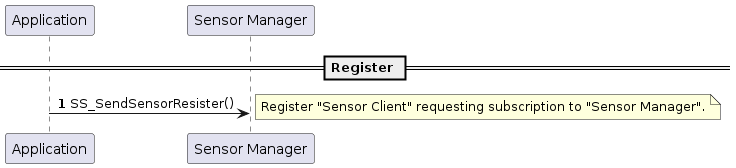
5.11.6.2.2. Create and Open
After completing preparations, "Step Counter" will be generated and activated.
To generate "Step Counter" you need to call StepCounterCreate(PoolId).
For PoolId, you need to specify the ID defined in "Memory Manager Configuration".
As a return value, a pointer to the instance of "Step Counter" is returned.
FAR StepCounterClass *step_counter_instance;
step_counter_instance = StepCounterCreate(SENSOR_DSP_CMD_BUF_POOL);To activate "Step Counter" you need to call StepCounterOpen(FAR StepCounterClass*).
For StepCounterClass *, you need to specify a pointer to the instance of "Step Counter" which is the return value of StepCounterCreate.
StepCounterOpen(step_counter_instance);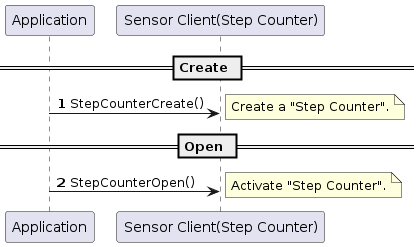
5.11.6.2.3. Set stride
The initial value of stride when sensing is 60 cm in walking condition and 80 cm in running condition.
To change this initial value, you need to call StepCounterSet(FAR StepCounterClass*, StepCounterSetting*).
For StepCounterClass *, you need to specify a pointer to the instance of "Step Counter" which is the return value of StepCounterCreate.
For StepCounterSetting *, please set the stride length of walking state and running state in step_length in unit cm. The maximum stride is 250 cm.
step_mode is fixed "STEP_COUNTER_MODE_FIXED_LENGTH"
StepCounterSetting set;
set.walking.step_length = 70; /* Set stride to 70 cm */
set.walking.step_mode = STEP_COUNTER_MODE_FIXED_LENGTH;
set.running.step_length = 90; /* Set stride to 90 cm */
set.running.step_mode = STEP_COUNTER_MODE_FIXED_LENGTH;
StepCounterSet(step_counter_instance, &set);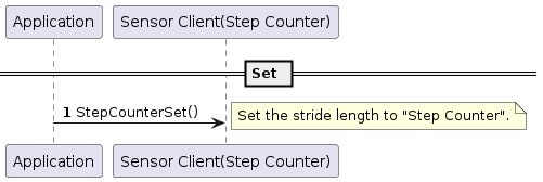
"Step Counter" sends data to the worker on the DSP via StepCounterWrite at the timing of "Subscribe" of "Accelerometer" and performs sensing processing.
The sequence at this time is shown below.
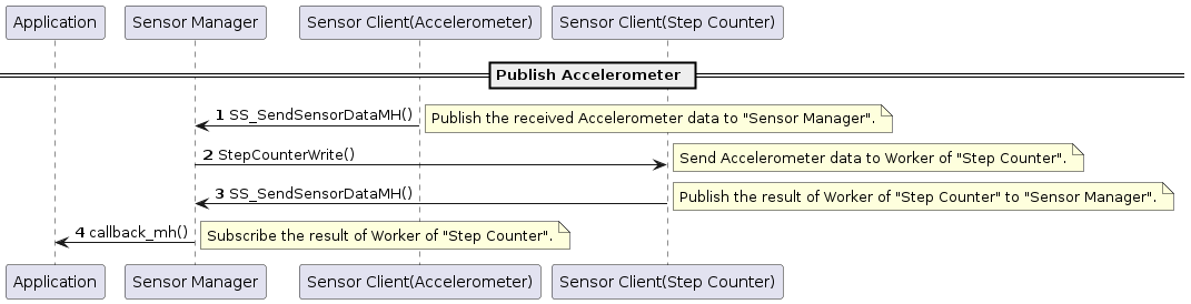
5.11.6.2.4. Close
To disable "Step Counter", you need to call StepCounterClose(FAR StepCounterClass*).
For StepCounterClass *, you need to specify a pointer to the instance of "Step Counter" which is the return value of StepCounterCreate.
StepCounterClose(step_counter_instance);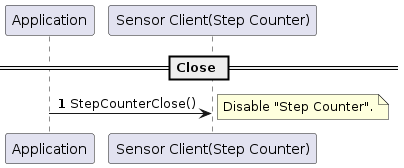
5.11.6.2.5. Release from Sensor Manager
After disable "Step Counter", cancel registration to "Sensor Manager".
In this case, please suspend the operation of "Sensor Client" which subscribes to "Step Counter" in advance.
sensor_command_register_t reg;
rel.header.code = ReleaseClient;
rel.self = stepcounterID;
SS_SendSensorRelease(&rel);5.11.6.3. Build Configurations
In order to use the function of "Step Counter" please follow these instructions:
cd sdk
tools/config.py -m
You need to open the Config menu and configure the following Config.
Select options in below:
[CXD56xx Configuration]
[I2C0] <= Y
[Sensor Control Unit] <= Y
[Memory manager] <= Y
[Memory Utilities]
[Memory manager] <= Y
[Message] <= Y
[Drivers]
[Sensor Drivers] <= Y
[Bosch BMI160 Sensor support] <= Y
[SCU Sequencer] <= Y
[Sensing]
[Sensing manager] <= Y
[Step counter] <= Y
[ASMP] <= Y
5.11.6.4. Worker
Worker runs on other Core and analyzes sensor data sent from Supervisor.
And it returns the processing result (number of steps, state.) of the requested event.
The worker of "Step Counter" needs the following data for analysis.
・ Accelerometer data(32Hz、32samples/1sec)
5.11.6.4.1. APIs
The "Step Counter" Worker provides the following 3 APIs.
| APIs | Description |
|---|---|
Init |
Initialize for AESM(Activity Engine and Step Meter) library. |
Exec |
Execute calculate on sensor data on AESM library. |
Flush |
End execute process of AESM library. |
These APIs are called depending on the event type and command type contained in packets sent from Supervisor.
The relationship is as follow.
SensorDspCmd dsp_cmd;
dsp_cmd.header.sensor_type = StepCounter;
dsp_cmd.header.event_type = InitEvent;SensorDspCmd dsp_cmd;
dsp_cmd.header.sensor_type = StepCounter;
dsp_cmd.header.event_type = ExecEvent;
dsp_cmd.exec_aesm_cmd.cmd_type = AESM_CMD_UPDATE_ACCELERATION;SensorDspCmd dsp_cmd;
dsp_cmd.header.sensor_type = StepCounter;
dsp_cmd.header.event_type = FlushEvent;5.11.6.5. Step Counter Example
There is "Step Counter" example as a sample application of "Step Counter". Here, we will explain how to use it.
5.11.6.5.1. Preparation
In build configuration setup Step counter sensor example to Y to use the sample programs for "Step Counter".
Select options in below:
[Examples] [Step counter sensor example] <= Y
Alternatively, use the default configuration of "Step Counter".
./tools/config.py examples/step_counter
To set the memory management library (Memory Manager) and the inter-task communication library (Message Library) as follow:
It is necessary to define the MemoryLayout (pool) which is necessary when using the "Step Counter" function.
Definition is done in the MemoaryLayout definition file, and it is possible to generate a header file to be included in the code with the tool.
In the example of "Step Counter", do as follow:
cd examples/step_counter/config python3 mem_layout.conf
"mem_layout.h", "fixed_fence.h" and "pool_layout.h" will be generated.
"mem_layout.h" is referred by msgq_layout tool.
The contents of the MemoaryLayout definition file (mem_layout.conf) are as follow:
FixedAreas
# name, device, align, size, fence
["SENSOR_WORK_AREA", "SHM_SRAM", U_STD_ALIGN, 0x0001e000, False],
["MSG_QUE_AREA", "SHM_SRAM", U_STD_ALIGN, 0x00001000, False],
["MEMMGR_WORK_AREA", "SHM_SRAM", U_STD_ALIGN, 0x00000200, False],
["MEMMGR_DATA_AREA", "SHM_SRAM", U_STD_ALIGN, 0x00000100, False],The explanation of each parameter is as follow:
| Parameter | Description |
|---|---|
name |
area name (name starting with uppercase letters and ending with "_AREA", uppercase letters, numbers, _ can be used) |
device |
Device name of MemoryDevices to reserve space |
align |
Start alignment of the region. Specify a multiple of MinAlign (= 4) except 0 |
size |
size of the region. Specify a value of a multiple of 4 except 0 |
fence |
Specify whether fence is enabled or disabled (This item is ignored when UseFence is false) |
The purpose of each name is as follow:
| SENSOR_WORK_AREA |
Sensor fusion uses |
| MSG_QUE_AREA |
MessageQueue (fixed name). Do not exceed the size of (MSGQ_END_DRM - MSGQ_TOP_DRAM) of msgq_id.h. |
| MEMMGR_WORK_AREA |
Work area used by Memory Manager (fixed name, fixed size) |
| MEMMGR_DATA_AREA |
Data area used by Memory Manager (fixed name, fixed size) |
Make sure that the total size of each name does not exceed the size of the shared memory secured by mpshm_init(), mpshm_remap().
PoolAreas
# name, area, align, pool-size, seg, fence
["SENSOR_DSP_CMD_BUF_POOL", "SENSOR_WORK_AREA", U_STD_ALIGN, U_SENSOR_DSP_CMD_POOL_SIZE, U_SENSOR_DSP_CMD_SEG_NUM, False],
["ACCEL_DATA_BUF_POOL", "SENSOR_WORK_AREA", U_STD_ALIGN, U_ACCEL_DATA_BUF_POOL_SIZE, U_ACCEL_DATA_BUF_SEG_NUM, False],
["GNSS_DATA_BUF_POOL", "SENSOR_WORK_AREA", U_STD_ALIGN, U_GNSS_DATA_BUF_POOL_SIZE, U_GNSS_DATA_BUF_SEG_NUM, False],The explanation of each parameter is as follow:
| Parameter | Description |
|---|---|
name |
pool name (name starting with uppercase letters and ending with "_POOL", upper case letters, numbers, _ can be used) |
area |
Area name of FixedArea to be used as pool area. The area must be located in the RAM |
align |
Starting alignment of the pool. Specify a multiple of MinAlign (= 4) except 0 |
pool size |
size of the pool. A value of a multiple of 4 except 0. In the Basic pool, segment size * number of segments |
seg |
Number of segments. Specify a value between 1 and 255 |
fence |
Specify whether the fence is valid or invalid. This item is ignored when UseFence is false |
The purpose of each name is as follow:
| SENSOR_DSP_CMD_BUF_POOL |
send/receive buffer area with Worker |
| ACCEL_DATA_BUF_POOL |
Accelerometer data buffer area |
|
Refer to examples/step_counter/config/mem_layout.conf for details of each definition. If the setting changes, please use the tool to generate a new header file. |
It is necessary to define the MessageQueue which is necessary when using the "Step Counter" function. Definition is done in the MessageQueueLayout definition file, and you can generate a header file to be included in the code with the tool.
In the example of "Step Counter", do as follow:
cd examples/step_counter/config python3 msgq_layout.conf
"msgq_id.h" and "msgq_pool.h" will be generated.
Copy all of the generated header files into include directory.
cd examples/step_counter/config mv *.h ../include
The description contents of the MessageQueueLayout definition file (msgq_layout.conf) are as follow:
MsgQuePool
# ID, n_size n_num h_size h_nums
["MSGQ_SEN_MGR", 40, 8, 0, 0],The explanation of each parameter is as follow:
| Parameter | Description |
|---|---|
ID |
Specify the name of the message queue pool ID as a character string beginning with "MSGQ_". |
n_size |
Number of bytes of each element of the normal priority queue (8 or more and 512 or less). Specify fixed header length (8 bytes) + parameter length as a multiple of 4. |
n_num |
Number of elements of normal priority queue (1 or more and 16384 or less). |
h_size |
Number of bytes (0 or 8 to 512 inclusive) for each element of the high priority queue. Specify 0 when not in use. |
h_num |
Number of elements in the high priority queue (0 or 1 to 16384 or less). Specify 0 when not in use. |
Since n_size is the optimum value, please do not change.
There is no need to change n_num, but when using the "Step Counter" function with other Application, it may be necessary to increase the value considering the load.
Use h_size and h_nums when you want to process the "Step Counter" function preferentially.
|
Refer to examples/step_counter/config/msgq_layout.conf for details on each definition. If the settings change, please use the tool to generate a new header file. |
5.12. JPEG Decoder
5.12.1. Overview
Spresense JPEG Decoder is based on libjpeg library developed by IJG.
JPEG Decoder API is compliant with original libjpeg, however there are customized features for Spresense which are explained in this chapter.
In the following document, libjpeg instance refers to the struct jpeg_decompress_struct type variable which libjpeg application must prepare.
5.12.2. Customized features for Spresense
Output format(color space)
All formats supported by original libjpeg have at least 24 bits/pixel (also called bits-per-pixel or just bpp).
Spresense support the following 16 bpp formats: Cb/Y/Cr/Y(YUV4:2:2) which requires less memory to be decoded.
The following defines are valid in Spresense.
Application have to set the out_color_space member of the libjpeg instance to one of the defines in the list below to specify what format to decode.
○ means that it is supported.
× means that it is not supported.
| define | meaning | bits/pixel | Spresense | original |
|---|---|---|---|---|
JCS_CbYCrY |
Cb/Y/Cr/Y(YUV4:2:2) |
16 |
○ |
× |
JCS_YCbCr |
Y/Cb/Cr(YUV) |
24 |
× |
○ |
JCS_RGB |
sRGB |
24 |
× |
○ |
JCS_CMYK |
C/M/Y/K |
32 |
× |
○ |
JCS_YCCK |
Y/Cb/Cr/K |
32 |
× |
○ |
Unit of reading decoded result
In addition to reading by the line which original libjpeg support, Spresense support reading by the MCU which has the smaller size.
| API | meaning | Spresense | original |
|---|---|---|---|
jpeg_read_scanlines |
line unit |
○ |
○ |
jpeg_read_mcus |
MCU unit |
○ |
× |
|
MCU or Minimum Coded Unit is the block of JPEG compression unit. The size is basically 8×8pixels and depends on compression and decode parameters. Compression parameters are set in JPEG header and decode parameters are passed from application. Application can check the MCU size from libjpeg instance after jpeg_start_decompress() as follow:
|
MCU size do not depend on image size.
Therefore, the larger the image size becomes, the more remarkable the difference between the above two units become as the following examples.
| unit | QVGA case | HD case | 5M case |
|---|---|---|---|
line |
320 |
1280 |
2560 |
MCU |
128 |
128 |
128 |
JPEG data input methods
Spresense support file descriptor in addition to file pointer and buffer similar to original libjpeg.
| API | meaning | Spresense | original |
|---|---|---|---|
jpeg_stdio_src |
file pointer |
○ |
○ |
jpeg_fd_src |
file descriptor |
○ |
× |
jpeg_mem_src |
buffer |
○ |
○ |
This file descriptor needs to be readable JPEG data by read() function.
For example, support file descriptor by socket() function, besides the file descriptor of regular file by open() function.
(Of course, in socket descriptor case, JPEG data need to be sent from peer directly.)
Error Handling
In both original libjpeg and Spresense, libjpeg API execution task is exited by exit() function when errors happen.
In order to avoid exit task, original libjpeg show an example which use setjmp/longjmp.
Spresense on the other hand, can not use this method because Spresense(NuttX) does not support setjmp/longjmp.
Spresense will support some alternative error handling methods to setjmp/longjmp in the future.
| libjpeg error handling premise that error handler do not return to the caller. If error handler return to the caller, libjpeg operation is not guaranteed. |
| End method of error handler | meaning | Spresense | original |
|---|---|---|---|
exit |
exit libjpeg API execution task |
○ |
○ |
longjmp |
nonlocal jump to stack context which is saved in setjmp |
× |
○ |
return |
return to the caller |
× |
× |
| "Error" include not only program error but also failure due to external factors. The representative errors are showed in Output to standard error output. |
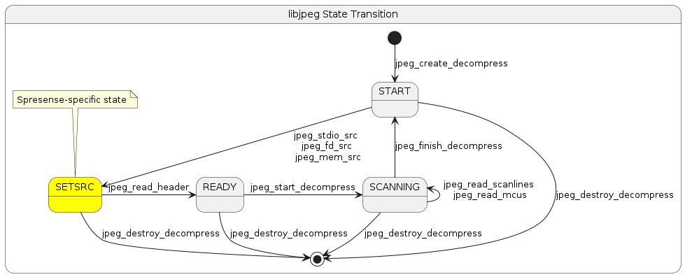
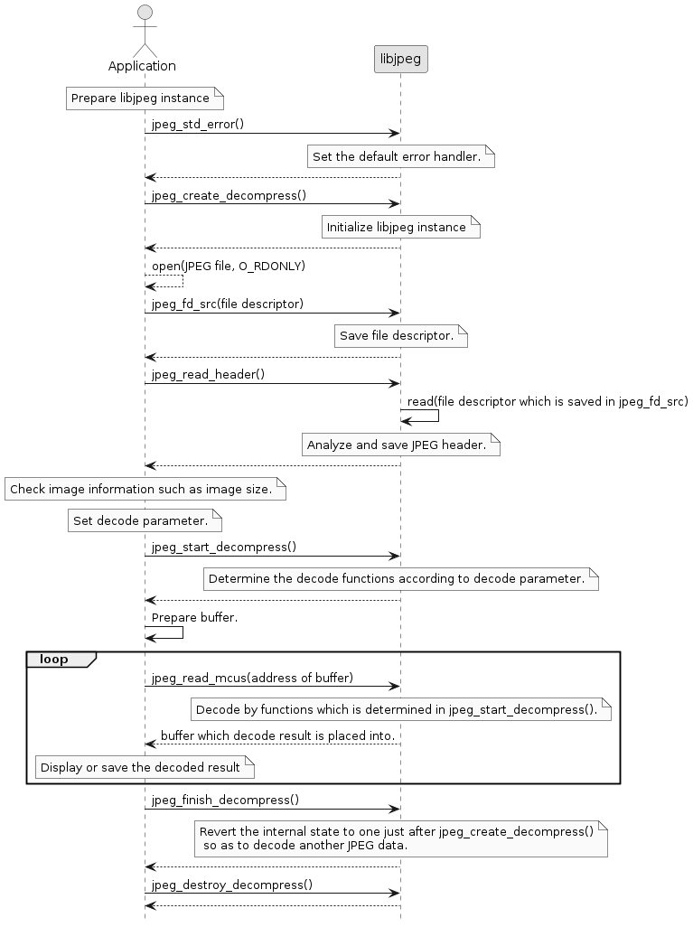
5.12.5. Output to standard error output
libjpeg library output english message to standard error output when detecting error or warning. The meaning and output reason of message is the same as the original libjpeg.
The frequent errors are as follow:
| output message | Error/Warning | output reason |
|---|---|---|
Improper call to JPEG library in state %d |
Error |
API execution order is not in the order of state transition diagram. |
Unsupported color conversion request |
Error |
Specify the non-supported output format. |
Not a JPEG file: starts with 0x%02x 0x%02x |
Error |
JPEG data is not start from 0xFF D8. |
Corrupt JPEG data: bad Huffman code |
Warning |
Decode error of Huffman code. |
Premature end of JPEG file |
Warning |
Reach to EOF without EOI marker. |
5.13. LTE
5.13.1. Overview
The LTE library can connect to the Internet via LTE network.
The LTE library provides APIs to manipulate the modem and the APIs needed for socket communication.
5.13.2. Terms and Abbreviations
| Terms | Explanation |
|---|---|
PDN |
Packet Data Network |
APN |
Access Point Name |
IMS |
IP Multimedia Subsystem |
IMSI |
International Mobile Subscriber Identity |
IMEI |
International Mobile Equipment Identifier |
eDRX |
extended Discontinuous Reception |
PSM |
Power Saving Mode |
CE |
Coverage Enhancement |
RAT |
Radio Access Technology |
5.13.3. State of the LTE library
The LTE library maintains an internal state to determine whether API calls are allowed or not. + <tbl_lte_api_state The state managed by the LTE API is shown in Table 43.
| Status | Description |
|---|---|
Uninitilized |
The LTE API is not working at all |
Initilized |
Ready to use the LTE API |
Power on ongoing |
The modem is powered on |
Power on |
The modem has been turned on and the communication status is set to Airplane Mode |
Radio on |
LTE network discovery is in progress |
PDN connected |
PDN construction is complete and IP address has been assigned to the modem |
Reset ongoing |
State during recovery from modem reset |
- State transitions
-
The state transition of the LTE library is shown in Figure 81.
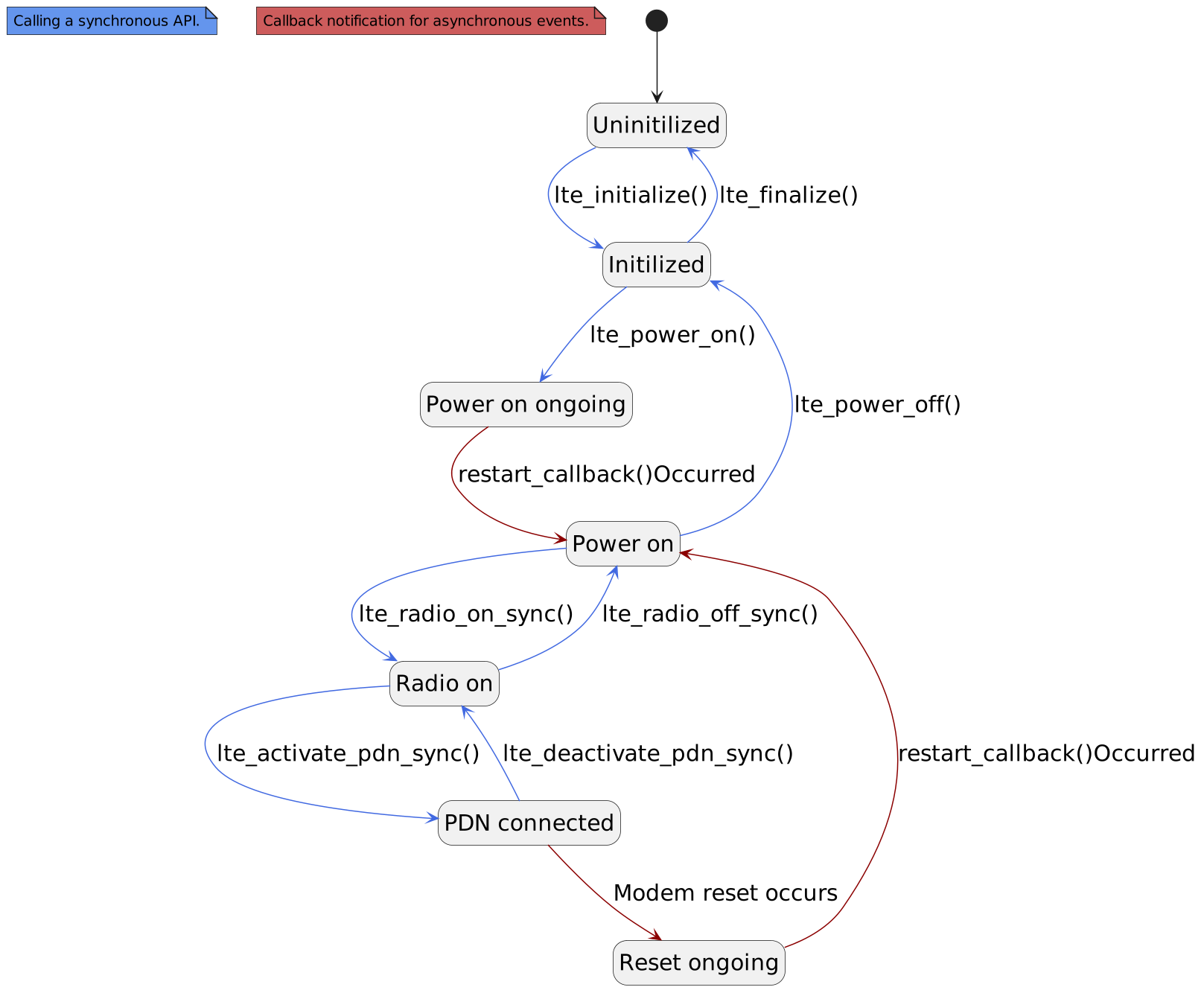
5.13.4. About APIs
Two types of LTE libraries are available: synchronous and asynchronous. For more information about the API, see LTE API Reference.
This section describes the features of synchronous and asynchronous APIs.
- Synchronous API
-
-
Notify the processing result with
return value. -
Blocking the task that called the API until the processing is
completedin the modem. -
If the return value is
-EPROTO, you can get the error code with the lte_get_errinfo() function. -
The argument whose attribute is OUT requires the user to allocate a region.
-
- Asynchronous API
-
-
Notify the processing result by
callback. -
Blocks the task that called the API until it
requeststhe modem to process it. -
The result of the processing request is notified by the return value.
-
The callback is registered with each API argument, and unregistered when the processing result is notified.
-
The same API cannot be called until the processing result is notified by the
callback. `-EINPROGRESS` will be notified in the return value.)
( -
If the callback notifies an error (LTE_RESULT_ERROR), you can get the error code with the lte_get_errinfo() function
-
|
There is one task context that the LTE library provides for calling callbacks. |
- API call availability
-
This section describes the availability of synchronous API calls in each state of the LTE library.
Legend:
〇 : Synchronous API calls possible
× : Cannot call synchronous API. The processing result (return value) becomes an error.
Table 44. LTE Library API call availability API
LTELibrary status.
Uninitilized
Initilized
Power on ongoing
Power on
Radio on
PDN connected
Reset ongoing
lte_initialize
〇
× ※1
× ※1
× ※1
× ※1
× ※1
× ※1
lte_finalize
× ※1
〇
〇
〇
〇
〇
〇
lte_set_report_restart
× ※4
〇
〇
〇
〇
〇
〇
lte_power_on
× ※4
〇
× ※3
× ※1
× ※1
× ※1
× ※3
lte_power_off
× ※4
× ※4
〇
〇
〇
〇
〇
lte_set_report_netinfo
× ※2
× ※2
× ※2
〇
〇
〇
× ※2
lte_set_report_simstat
× ※2
× ※2
× ※2
〇
〇
〇
× ※2
lte_set_report_localtime
× ※2
× ※2
× ※2
〇
〇
〇
× ※2
lte_set_report_quality
× ※2
× ※2
× ※2
〇
〇
〇
× ※2
lte_set_report_cellinfo
× ※2
× ※2
× ※2
〇
〇
〇
× ※2
lte_get_errinfo
× ※4
〇
〇
〇
〇
〇
〇
lte_activate_pdn_cancel
× ※2
× ※2
× ※2
〇
〇
〇
× ※2
lte_radio_on_sync
× ※2
× ※2
× ※2
〇
× ※5
× ※5
× ※2
lte_radio_off_sync
× ※2
× ※2
× ※2
× ※5
〇
〇
× ※2
lte_activate_pdn_sync
× ※2
× ※2
× ※2
× ※4
〇
〇
× ※2
lte_deactivate_pdn_sync
× ※2
× ※2
× ※2
× ※6
× ※6
〇
× ※2
lte_get_netinfo_sync
× ※2
× ※2
× ※2
〇
〇
〇
× ※2
lte_get_imscap_sync
× ※2
× ※2
× ※2
〇
〇
〇
× ※2
lte_get_version_sync
× ※2
× ※2
× ※2
〇
〇
〇
× ※2
lte_get_phoneno_sync
× ※2
× ※2
× ※2
〇
〇
〇
× ※2
lte_get_imsi_sync
× ※2
× ※2
× ※2
〇
〇
〇
× ※2
lte_get_imei_sync
× ※2
× ※2
× ※2
〇
〇
〇
× ※2
lte_get_pinset_sync
× ※2
× ※2
× ※2
〇
〇
〇
× ※2
lte_set_pinenable_sync
× ※2
× ※2
× ※2
〇
〇
〇
× ※2
lte_change_pin_sync
× ※2
× ※2
× ※2
〇/× ※7
〇/× ※7
〇/× ※7
× ※2
lte_enter_pin_sync
× ※2
× ※2
× ※2
〇/× ※8
〇/× ※8
〇/× ※8
× ※2
lte_get_localtime_sync
× ※2
× ※2
× ※2
〇
〇
〇
× ※2
lte_get_operator_sync
× ※2
× ※2
× ※2
〇
〇
〇
× ※2
lte_get_edrx_sync
× ※2
× ※2
× ※2
〇
〇
〇
× ※2
lte_set_edrx_sync
× ※2
× ※2
× ※2
〇
〇
〇
× ※2
lte_get_psm_sync
× ※2
× ※2
× ※2
〇
〇
〇
× ※2
lte_set_psm_sync
× ※2
× ※2
× ※2
〇
〇
〇
× ※2
lte_get_ce_sync
× ※2
× ※2
× ※2
〇
〇
〇
× ※2
lte_set_ce_sync
× ※2
× ※2
× ※2
〇
〇
〇
× ※2
lte_get_siminfo_sync
× ※2
× ※2
× ※2
〇
〇
〇
× ※2
lte_get_current_edrx_sync
× ※2
× ※2
× ※2
〇
〇
〇
× ※2
lte_get_current_psm_sync
× ※2
× ※2
× ※2
〇
〇
〇
× ※2
lte_get_quality_sync
× ※2
× ※2
× ※2
〇
〇
〇
× ※2
lte_get_cellinfo_sync
× ※2
× ※2
× ※2
〇
〇
〇
× ※2
lte_get_rat_sync
× ※2
× ※2
× ※2
〇
〇
〇
× ※2
lte_set_rat_sync
× ※2
× ※2
× ※2
〇
〇
〇
× ※2
lte_get_ratinfo_sync
× ※2
× ※2
× ※2
〇
〇
〇
× ※2
※1:If the return value is
-EALREADY
※2:If the return value is-ENETDOWN
※3:If the return value is-EINPROGRESS
※4:If the return value is-EPROTO、If the error code is-EOPNOTSUPP
※5:If the return value is-EPROTO、If the error code is-EALREADY
※6:If the return value is-EPROTO、If the error code is-EINVAL(session_id discrepancy)
※7:When PIN is invalid ⇒ x、When PIN is enabled⇒○
※8:If the PIN status is waiting for PIN/PUK release ⇒ ○, otherwise ⇒ × - The parameters stored in the modem’s nonvolatile memory by API calls
-
Indicates the parameters stored in the modem’s non-volatile memory by calling the synchronous API.
Table 45. Parameters stored in the modem’s non-volatile memory API Parameter Explanation lte_set_edrx_sync
enable
Enables or disables the eDRX function. Select
EnableorDisable.edrx_cycle
Operation cycle of eDRX operation.
lte_set_psm_sync
enable
Enable/Disable PSM function. Select
EnableorDisable.req_active_time
T3324 Value of the timer.
ext_periodic_tau_time
T3412 Value of the timer.
lte_set_rat_sync
rat
RAT used by modem. Select
LTE-M (LTE Cat-M1)、NB-IoT. ※1※1:If the second parameter persistent is
enabled, it is stored in the modem’s non-volatile memory.
5.13.5. Operating the modem
This section explains how to use the LTE library to manipulate the modem, using the sequence of events when using the synchronous API as an example.
5.13.5.1. Turn on the power.
The sequence for turning on the modem power is shown in Figure 82.
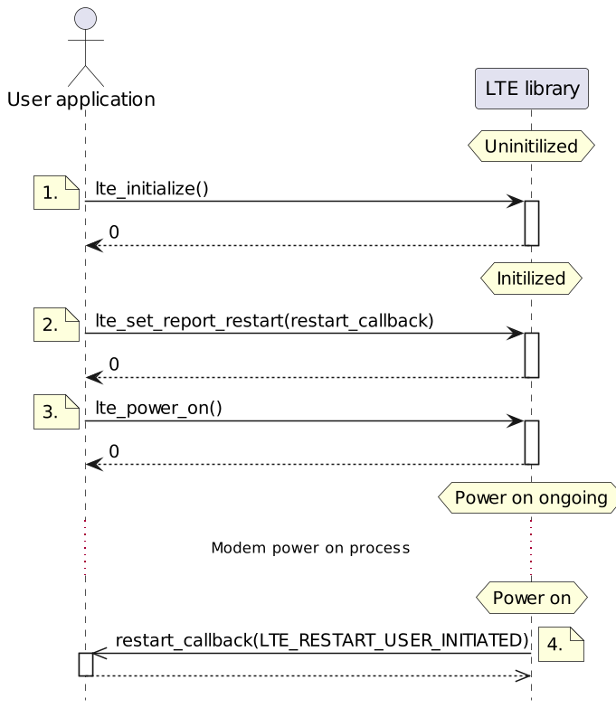
-
LTE Initialize the library.
-
Configure to receive callback notifications when the modem power-on process is completed or when the modem recovers from a spontaneous reset.
-
Power on the modem
-
A restart_callback() notification will be generated when the modem power-on process is completed. The reason for the notification will be `user-initiated startup'.
5.13.5.2. Get modem information
The function to get the modem information is shown in Figure 83.
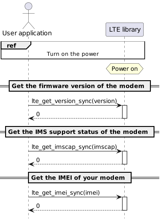
5.13.5.3. Register your modem to the LTE network
The sequence to register the modem to the LTE network is shown in Figure 84.
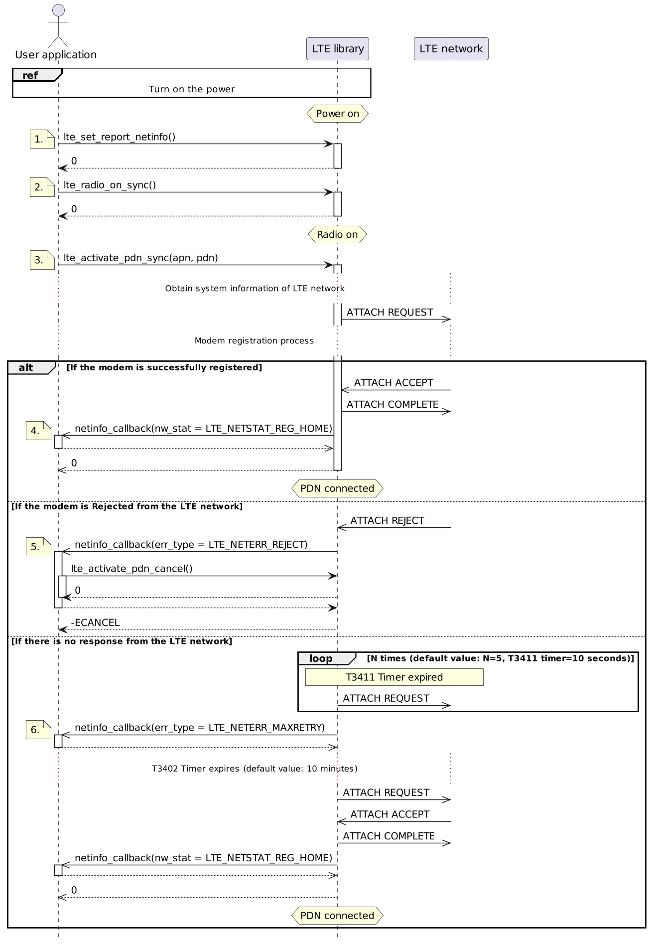
-
Configure to receive callback notifications when the LTE network information managed by the modem changes.
-
Turn on the modem’s radio.
-
Start building a communication path to transfer packets between the modem and the LTE network.
APN (Access Point Name) must be specified as an argument of the lte_activate_pdn_sync() function to build the communication path.
The APN specifies the connection point that is required for data communication in the LTE network. The following table shows the parameters of APN.Table 46. APN Parameters Parameter Explanation apn
Access point name
ip_type
APN Protocol. Select from
IPv4,IPv6, andIPv4v6.auth_type
Authentication type. Select from
PAP,CHAP, orNone.apn_type
APN Type.
UNKNOWN,DEFAULT,MMS,SUPL,DUN、HIPRI、IMS、CBS、IA、EMERGENCY、Select a combination ofuserName
User name.
password
Password.
The APN parameters should be set according to your SIM.
Currently, onlyIA|DEFAULTauthentication types are supported. If you set a combination of other authentication types, the lte_activate_pdn_sync() function will return an error (-EINVAL). -
If the modem registration is successful, the network status
LTE_NETSTAT_REG_HOMEwill be notified by netinfo_callback() and the return value of the lte_activate_pdn_sync() function will be returned as0. -
If the modem is Rejected from the LTE network, the network status
LTE_NETSTAT_REG_DENIEDand the error typeLTE_NETERR_REJECTwill be reported by netinfo_callback().
Within netinfo_callback(), call the lte_activate_pdn_cancel() function to cancel the modem registration process. If the modem registration process is canceled, the return value of the lte_activate_pdn_sync() function will be returned as-ECANCEL.-
If you do not call the lte_activate_pdn_cancel() function, the return value of the lte_activate_pdn_sync() function will not be returned.
-
If your modem is Rejected from the LTE network, please make sure you have correctly specified the APN that matches your SIM.
-
-
If there is no response from the LTE network due to problems with your signal, the network status
LTE_NETSTAT_REG_DENIEDand the error typeLTE_NETERR_MAXRETRYwill be reported by netinfo_callback().
After the T3402 timer expires, the modem will spontaneously start the registration process. If the registration of the modem is successful, the network statusLTE_NETSTAT_REG_HOMEwill be notified by netinfo_callback() and the return value of the lte_activate_pdn_sync() function will be returned as0.It is possible to call the lte_activate_pdn_cancel() function and return the lte_activate_pdn_sync() function with the return value
-ECANCEL, just as if the modem had been Rejected. After that, if the lte_activate_pdn_sync() function is performed again, the modem registration process will start even after the T3402 timer expires.
5.13.5.4. Get LTE network information
The function to get the LTE network information is shown in Figure 85.
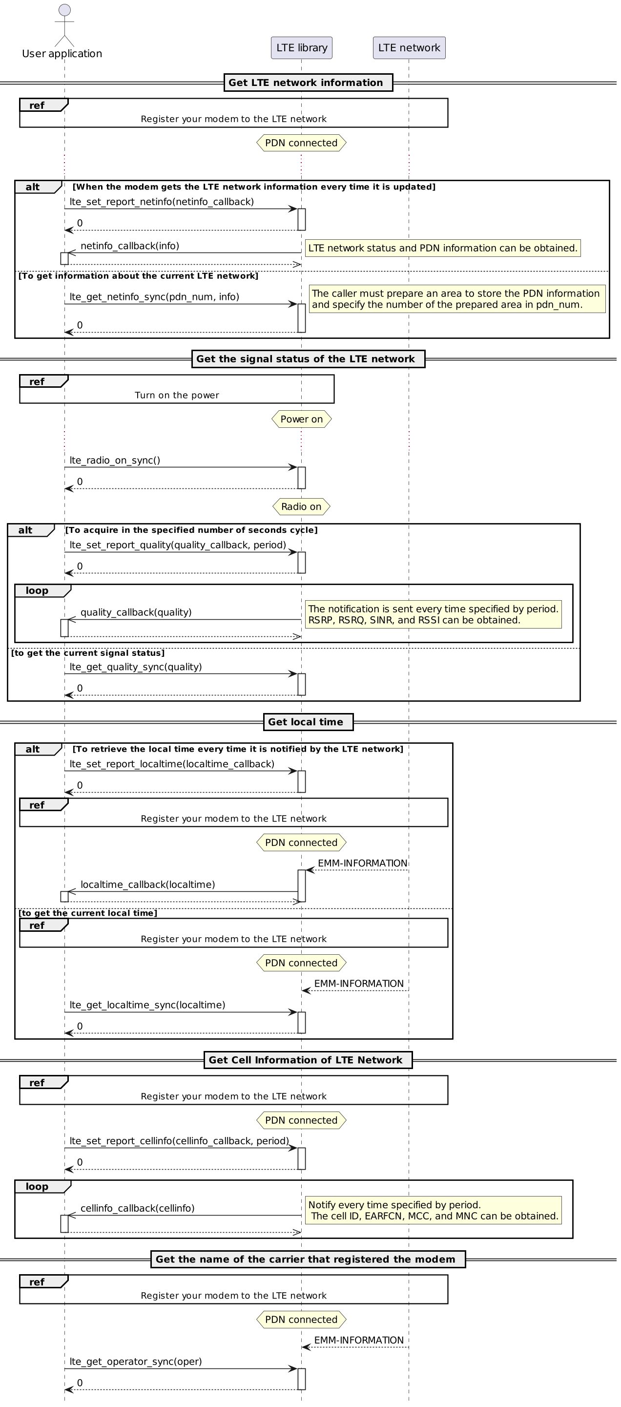
|
Currently, the maximum |
|
If you want to stop getting |
5.13.5.5. Disconnect the modem from the LTE network
The sequence for disconnecting the modem from the LTE network is shown in Figure 86.
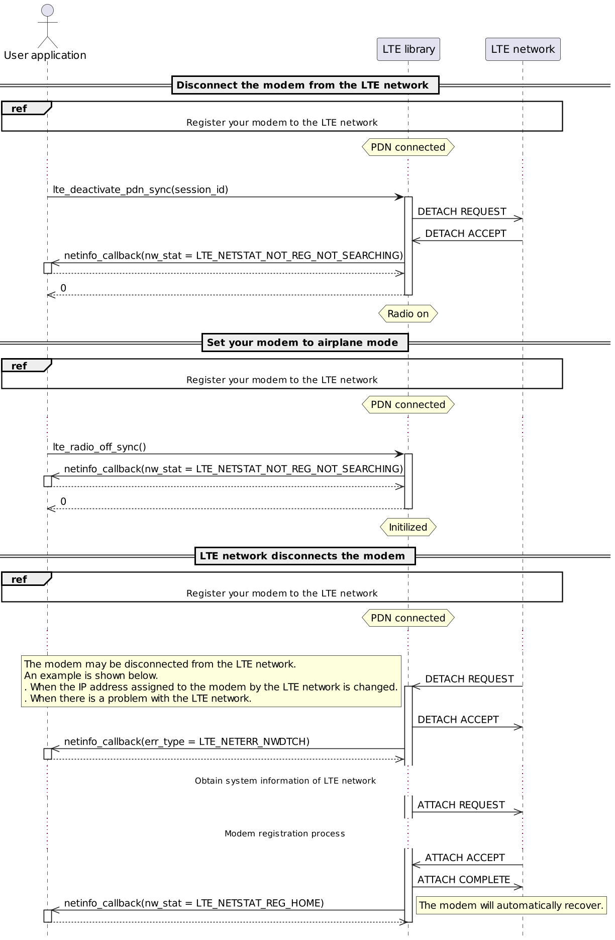
5.13.5.6. Operating the SIM
The functions to manipulate the SIM are shown in Figure 87.
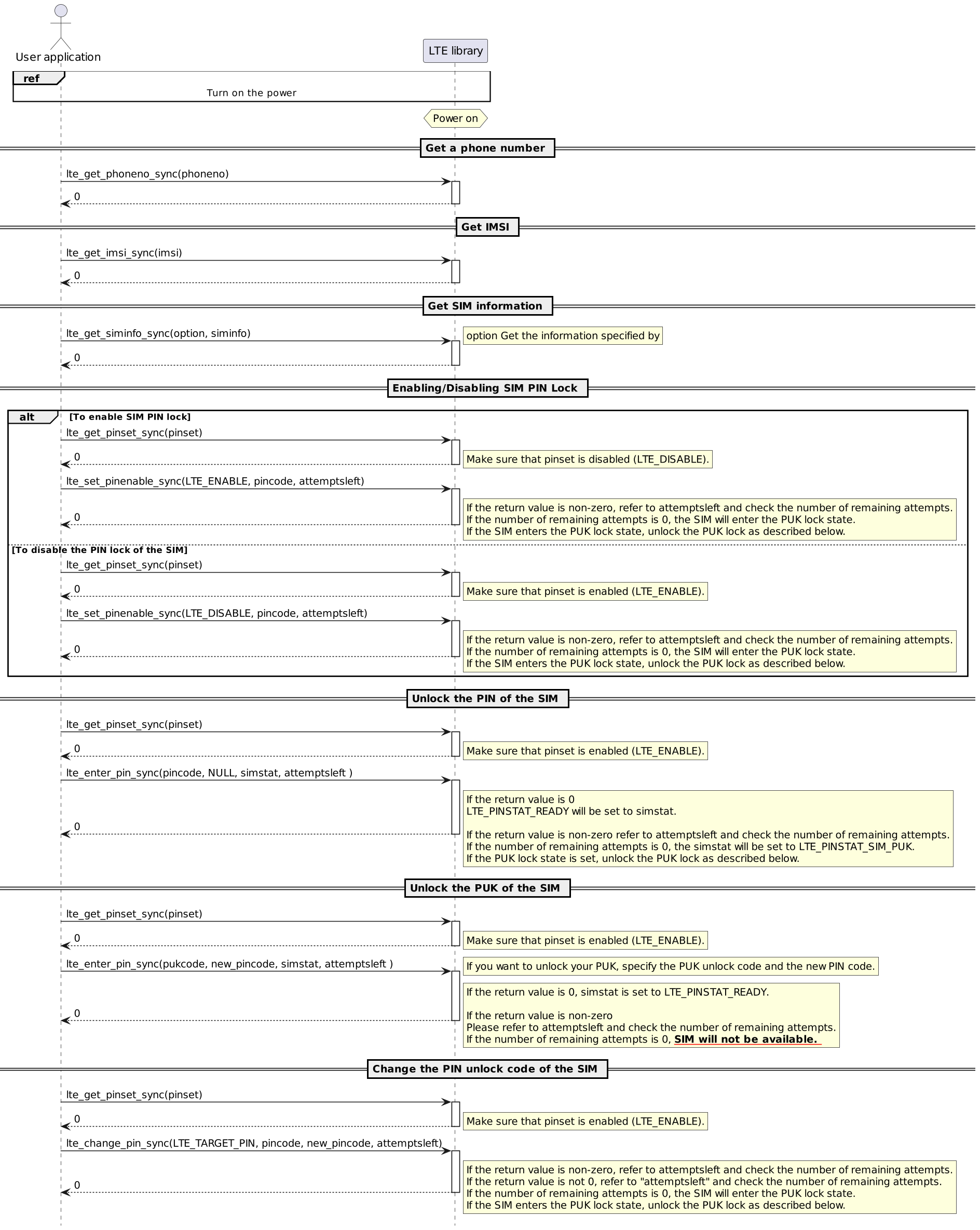
|
If you have a SIM lock, you will not be able to register your modem to the LTE network until you unlock the SIM lock. Currently, changing the PIN2 release code is not supported. |
|
Please note that if you fail to unlock the PUK until the number of remaining attempts reaches |
5.13.5.7. Set your modem to power saving settings
By enabling the eDRX and PSM functions of the modem, you can set the modem to a power-saving configuration. The sequence to enable the eDRX and PSM functions is shown in Figure 88.
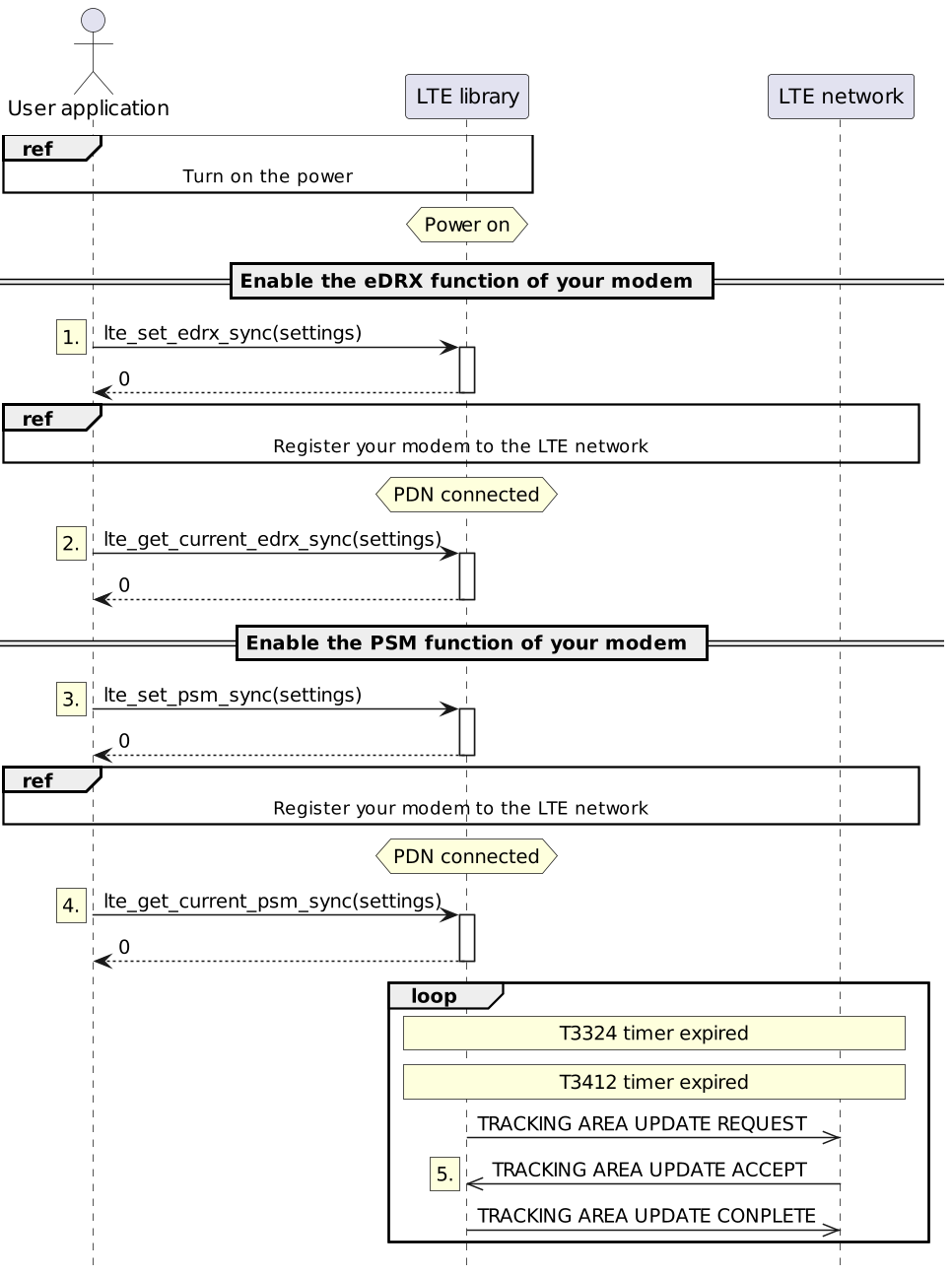
-
Enables the eDRX function of the modem. The following table shows the parameters to be specified.
Table 47. eDRX configuration parameters Parameter Explanation act_type
Operation type of eDRX. Currently, it is fixed to
WBS1.enable
Enables or disables the eDRX function. Select
EnableorDisable.edrx_cycle
Operation cycle of eDRX operation.
ptw_val
Paging time window.
Specifies the interval at which data is received during eDRX operation. -
The
eDRX cycleandPTWof the eDRX function are determined at the time the modem is registered with the LTE network, as the settings on the modem side may differ from the settings supported by the LTE network.
You can check the actual working eDRX settings with the lte_get_current_edrx_sync() function.The waveform of power consumption when the eDRX function is running with
eDRX cycleof 20.48 seconds andPTWof 6.4 seconds is shown in Figure 89. Figure 89. Power consumption waveform during eDRX function operation
PTWYou can receive incoming data only during the period of -
Enables the PSM function of the modem. The following table shows the parameters to be specified.
Table 48. PSM Configuration Parameters Parameter Explanation enable
Enable/Disable PSM function. Select
EnableorDisable.req_active_time
T3324 Value of the timer.
ext_periodic_tau_time
T3412 Value of the timer
-
The
T3324 timer valueandT3412 timer valueused by the PSM function are determined when the modem is registered to the LTE network.
You can check the actual working PSM settings with the lte_get_current_psm_sync() function.The value of
T3412 timermay not be available depending on your network. -
The
T3324 timer valueandT3412 timer valueused by the PSM function are updated by the LTE network in theTRACKING AREA UPDATE ACCEPTmessage.The waveform of the power consumption when the PSM function is running is shown in Figure 90.
 Figure 90. Power consumption waveform during PSM function operation
Data cannot be received until the
T3412 timerexpires. After the expiration of theT3412 timer, data can be received until the expiration of theT3324 timer.If the eDRX function is activated while the PSM function is running, the eDRX function will run from the start of the
T3324 timeruntil it expires.
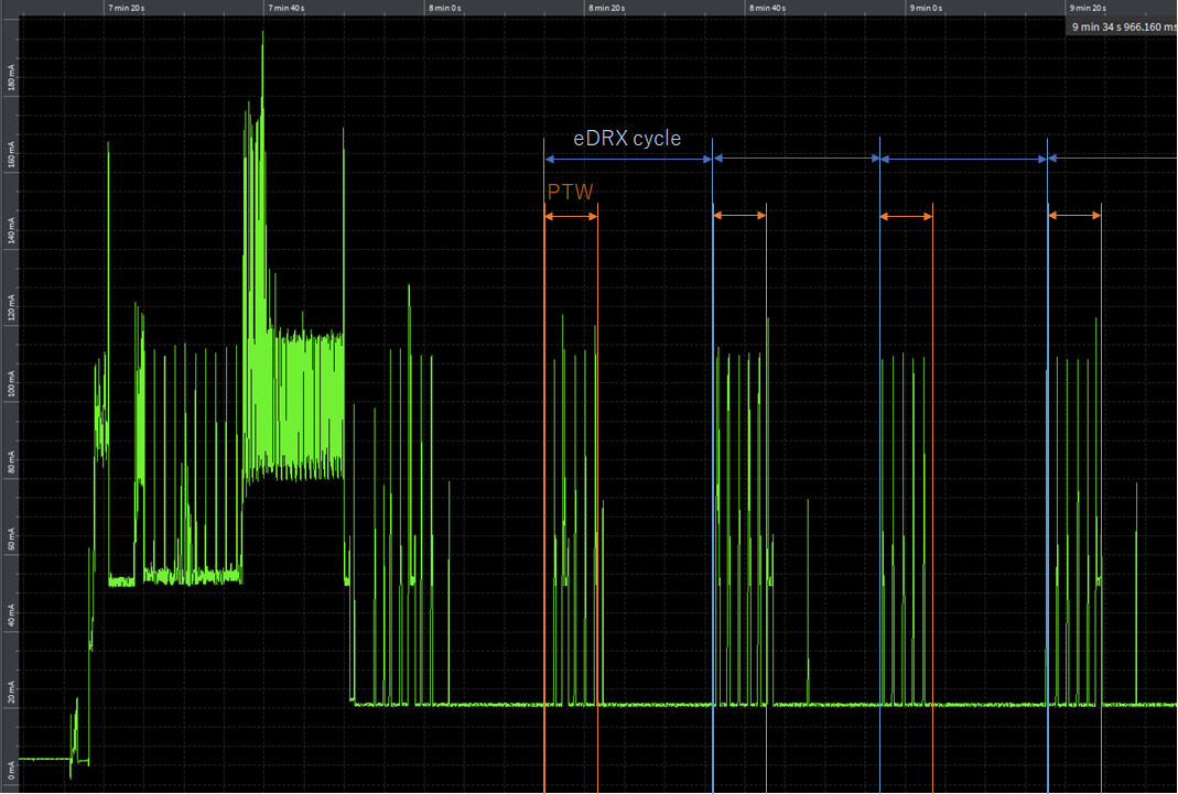
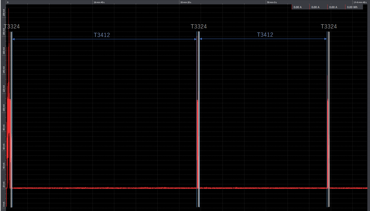
5.13.5.8. Recovery from modem reset
The sequence for when the modem resets for some reason is shown in Figure 91.
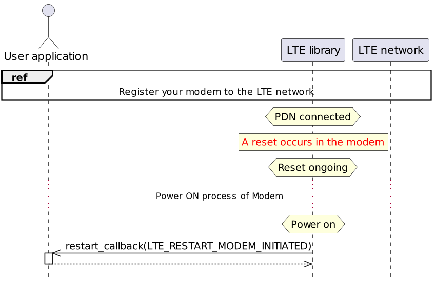
-
When a modem reset occurs, the state of the LTE library transitions to the
Reset ongoingstate. -
When the modem power on process is completed, the LTE library state will transition to the
Power onstate. + . After transition to thePower onstate, a restart_callback() notification occurs. The reason for the notification will be modem-driven startup. After the restart_callback() notification, the modem is ready for use.
5.13.6. Using the Socket API
Supports BSD-compatible socket interfaces.
For more information on the socket API, see NuttX Network Interfaces.
|
If the modem resets while using the Socket API, call the close() function. |
5.13.6.1. Use the modem’s TLS protocol
Using the modem’s TLS protocol can reduce the SPRESENSE memory.
|
The modem’s TLS protocol does not support part of mbedtls APIs. |
|
If the LTE firmware version is RK_03_00_00_00_00_04121_001, the TLS communication API may not work. (Please refer to here ) |
This section explains how to change the configuration of the modem to use the TLS protocol.
-
Open the menu screen
tools/config.py -m
-
Disable the TLS protocol for SPRESENSE.
Application Configuration -> Spresense SDK -> Externals -> mbed TLS Library (CONFIG_EXTERNALS_MBEDTLS)

-
Enable the TLS protocol in the modem.
Application Configuration -> Spresense SDK -> LTE -> Stub mbedTLS Support (CONFIG_LTE_NET_MBEDTLS)

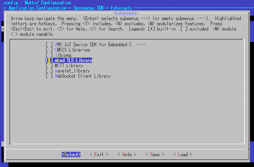
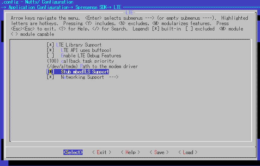
5.14. Alpha blend
5.14.1. Overview
The Alpha blend API imageproc_alpha_blend provides the function to blend two images (background (dst) and foreground (src)) with a specified ratio (alpha).
|
The supported pixel format is only YUV4:2:2. |
|
The alpha can be specified on a per-pixel basis and is a percentage of the src in 256 fractions.
|
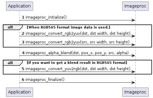
5.14.2. Alpha blend API details
You can specify background image (dst), foreground image (src), alpha image (alpha), and blend position coordinates (pos_x, pos_y) with respect to the origin of the pixel to be blended in dst.
For each image, you can also specify the clipping position (top-left coordinates (x1,y1) and bottom-right coordinates (x2, y2) of the rectangle).
|
Negative pos_x means the left rather than the left edge of the blended area. |
The blending in negative pos_x and pos_y case is as follow.
Only the areas enclosed in the yellow frame in the figure (overlapped areas) are updated by the blend results.
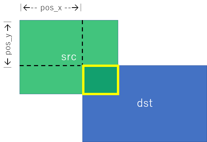
5.14.2.1. How to specify image information
All of 3 images are specified by structure imageproc_imginfo_t.
The members of structure imageproc_imginfo_t are as follow.
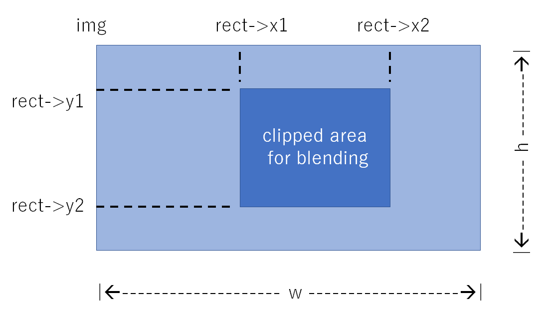
If rect is not set(rect = NULL), use the entire image.
5.14.2.1.2. src type
src supports type = IMAGEPROC_IMGTYPE_16BPP and IMAGEPROC_IMGTYPE_SINGLE.
| type | feature |
|---|---|
16BPP |
YUV4:2:2 image |
SINGLE |
Image which all pixels have the same color |
|
SINGLE is the special case of 16BPP, which limits the blending way, but reduces the memory requirements. |
5.14.2.1.3. alpha typeの指定
alpha supports type = IMAGEPROC_IMGTYPE_8BPP, IMAGEPROC_IMGTYPE_BINARY and IMAGEPROC_IMGTYPE_SINGLE.
| type | feature |
|---|---|
8BPP |
Set a different alpha value for each pixel. |
BINARY |
Specify whether to blend or not for each pixel. The alpha value for the blended pixels is fixed. |
SINGLE |
Specify the same value for all pixels. |
|
BINARY and SINGLE are the special cases of 8BPP, which limits the blending way, but reduces the memory requirements. |
5.15. Host Interface (HostIF)
5.15.1. Overview
The Host Interface (HostIF) provides the communication interface function with the external host device. The communication between the Host and Spresense uses the I2C(#3) or SPI(#2) pins of the CXD5602. The I2C and SPI peripherals are controlled by the internal sequencer on the CXD5602. The CXD5602 has an internal HostIF communication buffer, and the Spresense application can read and write to the communication buffer. The Spresense application sends and receives data from the Host by reading and writing to the communication buffer.
-
I2C communication function
-
SPI communication function
-
Data transmission/reception using the communication buffer
-
Interrupt notification function to the host
5.15.2. HostIF driver
This section describes how to use the HostIF driver to set the communication buffer and send/receive data to/from the host.
5.15.2.1. The configuration of the communication buffer
It has a total of 1 KByte communication buffer, which can be divided into up to 32 logical buffers. For each logical buffer, the transfer direction can be set either from Host to Spresense, or from Spresense to Host. To prevent the buffers from being accessed by Host and Spresense at the same time, an exclusive buffer locking mechanism is provided.
-
Total buffer size of 1KB
-
Divided into a maximum of 32 logical buffers
-
Configurable size and transfer direction for each logical buffer
-
Support exclusive lock mechanism for each logical buffer
An example of a communication buffer configuration is shown below. It consists of 3 receive buffers (0,2 and 3) and 3 transmit buffers (1,4,5) for Spresense.
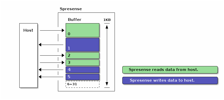
An example code for buffer configuration is shown below. For more details of structure, please refer to hostif.h.
I2C communication buffer setting
static struct hostif_i2cconf_s conf =
{
.address = 0x24, /* own I2C slave address */ (1)
//[Index] = { Size, Direction | Attributes }, (2)
.buff[0] = { 0x100, HOSTIF_BUFF_ATTR_READ | HOSTIF_BUFF_ATTR_VARLEN },
.buff[1] = { 0x100, HOSTIF_BUFF_ATTR_WRITE | HOSTIF_BUFF_ATTR_VARLEN },
.buff[2] = { 0x080, HOSTIF_BUFF_ATTR_READ | HOSTIF_BUFF_ATTR_FIXLEN },
.buff[3] = { 0x080, HOSTIF_BUFF_ATTR_READ | HOSTIF_BUFF_ATTR_FIXLEN },
.buff[4] = { 0x080, HOSTIF_BUFF_ATTR_WRITE | HOSTIF_BUFF_ATTR_FIXLEN },
.buff[5] = { 0x080, HOSTIF_BUFF_ATTR_WRITE | HOSTIF_BUFF_ATTR_FIXLEN },
};| 1 | I2C slave address definition. |
| 2 | The size, direction and attribute definitions for each communication buffer. |
SPI communication buffer setting
static struct hostif_spiconf_s conf =
{
//[Index] = { Size, Direction | Attributes }, (1)
.buff[0] = { 0x100, HOSTIF_BUFF_ATTR_READ | HOSTIF_BUFF_ATTR_VARLEN },
.buff[1] = { 0x100, HOSTIF_BUFF_ATTR_WRITE | HOSTIF_BUFF_ATTR_VARLEN },
.buff[2] = { 0x080, HOSTIF_BUFF_ATTR_READ | HOSTIF_BUFF_ATTR_FIXLEN },
.buff[3] = { 0x080, HOSTIF_BUFF_ATTR_READ | HOSTIF_BUFF_ATTR_FIXLEN },
.buff[4] = { 0x080, HOSTIF_BUFF_ATTR_WRITE | HOSTIF_BUFF_ATTR_FIXLEN },
.buff[5] = { 0x080, HOSTIF_BUFF_ATTR_WRITE | HOSTIF_BUFF_ATTR_FIXLEN },
};| 1 | The size, direction and attribute definitions for each communication buffer. |
5.15.2.2. Initialize HostIF driver
Set the buffer configuration as an argument and call the initialization function to initialize the HostIF driver.
Initialize I2C communication buffer
ret = hostif_i2cinitialize(&conf);Initialize SPI communication buffer
ret = hostif_spiinitialize(&conf);If the initialization completes successfully, the hostif driver will create the device files for /dev/hostif{r|w}{0-31}.
In the example described above, the device files are created as below.
| Index | Size | Direction | Device filename |
|---|---|---|---|
0 |
0x100 |
Read |
/dev/hostifr0 |
1 |
0x100 |
Write |
/dev/hostifw1 |
2 |
0x080 |
Read |
/dev/hostifr2 |
3 |
0x080 |
Read |
/dev/hostifr3 |
4 |
0x080 |
Write |
/dev/hostifw4 |
5 |
0x080 |
Write |
/dev/hostifw5 |
5.15.2.3. Receive by HostIF driver
Open a device file with the read-attribute and read the contents from the communication buffer using read() system call. By reading, the data sent from the host can be received.
int fd = open("/dev/hostifr0", O_RDONLY [| O_NONBLOCK]); (1)
size = read(fd, buffer, sizeof(buffer)); (2)| 1 | Call open() system call with oflags of O_RDONLY. To read with non-blocking, append O_NONBLOCK to oflags. |
| 2 | Read the contents of the communication buffer by read() system call. On success, the number of bytes read is returned. |
5.15.2.4. Send by HostIF driver
Open a device file with the write-attribute and write the contents to the communication buffer using write() system call. By writing, the data sent from the host can be received.
int fd = open("/dev/hostifw1", O_WRONLY [| O_NONBLOCK]); (1)
size = write(fd, buffer, sizeof(buffer)); (2)| 1 | Call open() system call with oflags of O_WRONLY. To write with non-blocking, append O_NONBLOCK to oflags. |
| 2 | Write the contents of the communication buffer by write() system call. On success, the number of bytes written is returned. |
5.15.3. Host communication specifications
This section describes the communication specifications of the host that communicates with Spresense.
The communication formats are defined for the host to access the communication buffer via I2C or SPI bus. The host sends a 1-byte ICMD (Interface CoMmanD) at the beginning of a transaction. The transferred ICMD determines the communication content and the communication format. In all transfers, bits are transferred with MSB first, and multi-byte data are transferred with LSB first.
5.15.3.1. Host communication format (I2C)
The R1/R2/R3/D1/W1/W2/W3 formats are defined as I2C communication formats. For data reception, the D1 format is used immediately after the R1/R2/R3 formats. The D1 format can be started with the RESTART condition. For data transmission, the W1/W2/W3 formats are used.
The R1 format is used to read a fixed-length size. The actual data reception is done by using the D1 format after this format.
S |
SlaveAddr |
W |
A |
ICMD(0x80~0x9F) |
A |
P |
The R2 format is used to read a variable-length size. It can also be used to specify a flag to keep a buffer lock. The actual data reception is done by using the D1 format after this format.
S |
SlaveAddr |
W |
A |
ICMD(0xA0~0xBF) |
A |
Length(LSB) |
A |
Flag+Length(MSB) |
A |
P |
The R3 format is used to read a variable-length size. It can also be used to specify a flag to keep a buffer lock. The actual data reception is done by using the D1 format after this format. It reads from the position of the buffer specified by AddressOffset.
S |
SlaveAddr |
W |
A |
ICMD(0xC0~0xDF) |
A |
AddressOffset |
A |
Length(LSB) |
A |
Flag+Length(MSB) |
A |
P |
The D1 format is used by the Host to read data from the communication buffer. The data is received after a 1-byte status flag. The size of the received data is a fixed size for the R1 format and a size specified by the R2/R3 format.
S |
SlaveAddr |
R |
A |
Status |
A |
Data |
A |
…. |
A |
…. |
N |
P |
The W1 format is used to transmit data of fixed-length size. Please add dummy data (1 byte) to the end of the data.
S |
SlaveAddr |
W |
A |
ICMD(0x80~0x9F) |
A |
Data |
A |
…. |
A |
dummy |
A |
P |
The W2 format is used to transmit data of variable-length size. It can also be used to specify a flag to keep a buffer lock. The transfer length is a size specified by Length. Please add dummy data (1 byte) to the end of the data.
S |
SlaveAddr |
W |
A |
ICMD(0xA0~0xBF) |
A |
Length(LSB) |
A |
Flag+Length(MSB) |
A |
Data |
A |
…. |
A |
dummy |
A |
P |
The W3 format is used to transmit data of variable-length size. It can also be used to specify a flag to keep a buffer lock. It writes to the position of the buffer specified by AddressOffset. The transfer length is a size specified by Length. Please add dummy data (1 byte) to the end of the data.
S |
SlaveAddr |
W |
A |
ICMD(0xC0~0xDF) |
A |
AddressOffset |
A |
Length(LSB) |
A |
Flag+Length(MSB) |
A |
Data |
A |
…. |
A |
dummy |
A |
P |
Each field of the format shows as below.
- SlaveAddr
-
This address is used to specify a slave device in the I2C specification.
- ICMD
-
This is a 1-byte command notified by the host to determine the kind of communication. See ICMD table for more details.
- Length, Flag
-
Length is a 14-bit data specified by the host, which informs the transfer length for a transaction. The unit is in bytes. The transfer length is transferred as 2 bytes of data, with the lower 8 bits at first, followed by the upper 6 bits. The bit7 of the byte data is reserved, and bit6 is the buffer lock flag.
Byte Bit Description Length(LSB)
[7:0]
Length[7:0] Transfer length(lower 8bit)
Flag+Length(MSB)
[7:7]
Reserved
[6:6]
Buffer lock flag (1:Keep Lock, 0:Unlock)
[5:0]
Length[13:8] Transfer length(upper 6bit)
The buffer lock flag is a 1-bit flag specified by the host. When this flag is 1, the host keeps to lock the logical communication buffer. When this flag is 0, the host unlocks the logical communication buffer at the end of the transaction. During the host is locking the buffer, the operations from the slave are prohibited.
- AddrOffset
-
This is 1-byte data specified by the host. By specifying the address offset, the host can set the start position of the logical buffer. The unit is either 1, 2, 4, or 8 bytes, and is set when initializing the communication buffer.
- Status
-
This is 1-byte data received by the host. Bit0 (LSB) is the status of lock failure. It is set when the host fails to lock the logical buffer.
Byte Bit Description Status
[7:1]
Reserved
[0:0]
lock status(1:failure, 0:success)
- dummy
-
On W1, W2, and W3 formats, the host must transfer 1 byte of dummy data at the end of the transaction.
- Data
-
It is data payload.
5.15.3.2. Host communication format (SPI)
The R1/R2/R3/W1/W2/W3 formats are defined as SPI communication formats. For data reception, the R1/R2/R3 formats are used. For data transmission, the W1/W2/W3 formats are used.
The upper part of the figure shows SDO and the lower part shows SDI.
The R1 format is used to read a fixed-length size.
ICMD(0x80~0x9F) |
dummy |
dummy |
dummy |
dummy |
dummy |
dummy |
dummy |
Status |
Data |
…. |
…. |
The R2 format is used to read a variable-length size. It can also be used to specify a flag to keep a buffer lock. The data transfer length is the size specified by Length.
ICMD(0xA0~0xBF) |
Length(LSB) |
Flag+Length(MSB) |
dummy |
dummy |
dummy |
dummy |
dummy |
Status |
Data |
…. |
…. |
The R3 format is used to read a variable-length size. It can also be used to specify a flag to keep a buffer lock. It reads from the position of the buffer specified by AddressOffset. The data transfer length is the size specified by Length.
ICMD(0xC0~0xDF) |
AddressOffset |
Length(LSB) |
Flag+Length(MSB) |
dummy |
dummy |
dummy |
dummy |
Status |
dummy |
Data |
…. |
The W1 format is used to transmit data of fixed-length size. Please add dummy data (1 byte) to the end of the data.
ICMD(0x80~0x9F) |
Data |
…. |
…. |
…. |
dummy |
dummy |
dummy |
Status |
dummy |
dummy |
dummy |
The W2 format is used to transmit data of variable-length size. It can also be used to specify a flag to keep a buffer lock. The transfer length is a size specified by Length. Please add dummy data (1 byte) to the end of the data.
ICMD(0xA0~0xBF) |
Length(LSB) |
Flag+Length(MSB) |
Data |
…. |
…. |
dummy |
dummy |
dummy |
Status |
dummy |
dummy |
dummy |
dummy |
The W3 format is used to transmit data of variable-length size. It can also be used to specify a flag to keep a buffer lock. It writes to the position of the buffer specified by AddressOffset. The transfer length is a size specified by Length. Please add dummy data (1 byte) to the end of the data.
ICMD(0xC0~0xDF) |
AddressOffset |
Length(LSB) |
Flag+Length(MSB) |
Data |
…. |
dummy |
dummy |
dummy |
Status |
dummy |
dummy |
dummy |
dummy |
Each field of the format are shown below.
- ICMD
-
This is a 1-byte command notified by the host to determine the kind of communication. See ICMD table for more details.
- Length, Flag
-
Length is a 14-bit data specified by the host, which informs the transfer length for a transaction. The unit is in bytes. The transfer length is transferred as 2 bytes of data, with the lower 8 bits at first, followed by the upper 6 bits. The bit7 of the byte data is reserved, and bit6 is the buffer lock flag.
Byte Bit Description Length(LSB)
[7:0]
Length[7:0] Transfer length(lower 8bit)
Flag+Length(MSB)
[7:7]
Reserved
[6:6]
Buffer lock flag (1:Keep Lock, 0:Unlock)
[5:0]
Length[13:8] Transfer length(upper 6bit)
The buffer lock flag is a 1-bit flag specified by the host. When this flag is 1, the host keeps to lock the logical communication buffer. When this flag is 0, the host unlocks the logical communication buffer at the end of the transaction. During the host is locking the buffer, the operations from the slave are prohibited.
- AddrOffset
-
This is 1-byte data specified by the host. By specifying the address offset, the host can set the start position of the logical buffer. The unit is either 1, 2, 4, or 8 bytes, and is set when initializing the communication buffer.
- Status
-
This is 1-byte data received by the host. Bit0 (LSB) is the status of lock failure. It is set when the host fails to lock the logical buffer.
Byte Bit Description Status
[7:1]
Reserved
[0:0]
lock status(1:failure, 0:success)
- dummy
-
On W1, W2, and W3 formats, the host must transfer 1 byte of dummy data at the end of the transaction.
- Data
-
It is data payload.
5.15.3.3. ICMD table
ICMD definitions are shown below.
For reading a transfer size, reading and Writing data, set the index number of communication buffer to the lower 5 bits of ICMD. Raw, Masked, Mask, Set, and Clear of ICMD table are used to control interrupts. The interrupt function is described later.
0x00 |
0x01 |
0x02 |
0x03 |
0x04 |
0x05 |
0x06 |
0x07 |
0x08 |
0x09 |
0x0A |
0x0B |
0x0C |
0x0D |
0x0E |
0x0F |
|
0x00 |
Raw |
Masked |
Mask |
Status |
||||||||||||
0x10 |
Read transfer size [0x10 + Buffer Index] |
|||||||||||||||
0x20 |
||||||||||||||||
0x30 |
||||||||||||||||
0x40 |
||||||||||||||||
0x50 |
Set |
Clear |
||||||||||||||
0x60 |
||||||||||||||||
0x70 |
||||||||||||||||
0x80 |
Read/Write fixed-length (R1/W1 format) [0x80 + Buffer Index] |
|||||||||||||||
0x90 |
||||||||||||||||
0xA0 |
Read/Write variable-length (R2/W2 format) [0xA0 + Buffer Index] |
|||||||||||||||
0xB0 |
||||||||||||||||
0xC0 |
Read/Write variable-length with offset (R3/W3 format) [0xC0 + Buffer Index] |
|||||||||||||||
0xD0 |
||||||||||||||||
0xE0 |
||||||||||||||||
0xF0 |
||||||||||||||||
5.15.3.3.1. ICMD(0x0E) Get status
ICMD (0x0E) is used to read the communication status at R1 format. During SPI communication or I2C read communication, ICMD(0x0E) is not necessary because the status is included in the received data. It is only used after I2C Write communication. This ICMD can be used to know whether the transfer was successful or not.
An example of the format for I2C communication is shown below.
Status[0:0]=0 means the success on the lock of logical buffer, but Status[0:0]=1 means the failure.
S |
SlaveAddr |
W |
A |
ICMD(0x0E) |
A |
P |
S |
SlaveAddr |
R |
A |
Status |
A |
Status |
A |
P |
5.15.3.4. Communication interrupt
The interrupt to the host is asserted when each buffer is writable or readable using a HIF_IRQ_OUT pin. The interrupt is cleared when the host writes to or reads from the communication buffer.
5.15.3.4.1. ICMD(0x03) Get the raw interrupt status
ICMD(0x03) can be used to get the raw interrupt status by R1 format. Each logical buffer number (0~31) is assigned to the Raw[31:0] bits.
An example of the format for SPI communication is shown below.
ICMD(0x03) |
dummy |
dummy |
dummy |
dummy |
dummy |
dummy |
dummy |
dummy |
Status |
Raw[7:0] |
Raw[15:8] |
Raw[23:16] |
Raw[31:24] |
5.15.3.4.2. ICMD(0x07) Get the masked interrupt status
ICMD(0x07) can be used to get the masked interrupt status by R1 format. Each logical buffer number (0~31) is assigned to the Masked[31:0] bits.
An example of the format for SPI communication is shown below.
ICMD(0x07) |
dummy |
dummy |
dummy |
dummy |
dummy |
dummy |
dummy |
dummy |
Status |
Masked[7:0] |
Masked[15:8] |
Masked[23:16] |
Masked[31:24] |
5.15.3.4.3. ICMD(0x0B) Get the interrupt mask value
ICMD(0x0B) can be used to get the interrupt mask value by R1 format. Each logical buffer number (0~31) is assigned to the Mask[31:0] bits. A bit set to 1 indicates that the interrupt is disabled, and a bit set to 0 indicates the interrupt is enabled.
An example of the format for SPI communication is shown below.
ICMD(0x0B) |
dummy |
dummy |
dummy |
dummy |
dummy |
dummy |
dummy |
dummy |
Status |
Mask[7:0] |
Mask[15:8] |
Mask[23:16] |
Mask[31:24] |
5.15.3.4.4. ICMD(0x53) Disable the interrupt
ICMD(0x53) can be used to disable the interrupt by W1 format. Each logical buffer number (0~31) is assigned to the Set[31:0] bits.
The interrupt mask is set by setting the specified bit where interrupts are to be disabled. The mask value of the bit set to 0 will not be changed.
An example of the format for SPI communication is shown below.
ICMD(0x53) |
Set[7:0] |
Set[15:8] |
Set[23:16] |
Set[31:24] |
dummy |
dummy |
dummy |
Status |
dummy |
dummy |
dummy |
5.15.3.4.5. ICMD(0x57) Enable the interrupt
ICMD(0x53) can be used to enable the interrupt by W1 format. Each logical buffer number (0~31) is assigned to the Clear[31:0] bits.
The interrupt mask is clear by setting the specified bit where interrupts are to be enabled. The mask value of the bit set to 0 will not be changed.
An example of the format for SPI communication is shown below.
ICMD(0x57) |
Clear[7:0] |
Clear[15:8] |
Clear[23:16] |
Clear[31:24] |
dummy |
dummy |
dummy |
Status |
dummy |
dummy |
dummy |
5.15.3.5. Host communication sequence
5.15.3.5.1. Host receive sequence
The sequence of the host receiving data from Spresense is shown below.
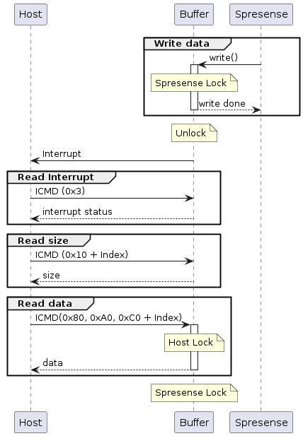
- Write data
-
Spresense writes data to the logical buffer. While writing data, Spresense locks the buffer and unlocks it when the writing is finished. While Spresense is locking the buffer, the lock operation from the host is prohibited. If the host is locking the buffer, write() will return an error.
- Interrupt
-
An interrupt to the host is asserted when the Spresense finishes to write and the logical buffer is ready to be read.
- Read Interrupt
-
By reading the interrupt status of the logical buffer, the host knows whether data is available in the logical buffer or not.
- Read size
-
If there is data in the logical buffer, the host can get the size of the data written from Spresense.
- Read data
-
The host reads the data by using ICMD R1/R2/R3 formats. While data is being read, the host locks the buffer and prohibits the Spresense from writing data. When the reading data is completed, the host will unlock the buffer and Spresense locks one automatically. If the Spresense locks the buffer, the read operation will return an error. The Status data of the reading format will let the host know if the read operation was successful or not.
5.15.3.5.2. Host transmit sequence
The sequence of the host sending data to Spresense is shown below.
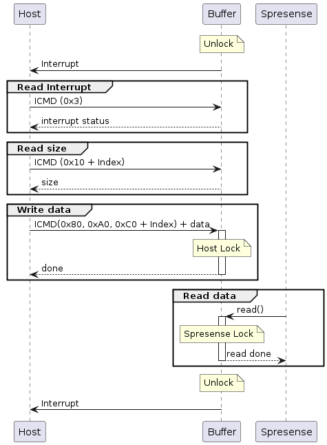
- Interrupt
-
An interrupt to the host is asserted when the logical buffer is writable.
- Read Interrupt
-
By reading the interrupt status of a logical buffer, the host knows whether the it is possible to write to the logical buffer or not.
- Read size
-
The host can get the size of the data that can be written to the logical buffer.
- Write data
-
The host write the data by using W1/W2/W3 formats. While writing data, the host locks the buffer and prohibits reading data from the Spresense. When the writing data is completed, the host will unlock the buffer and Spresense locks one automatically. If the Spresense lock the buffer, the write operation will return an error. The Status data of the format will let the host know if the write operation was successful or not.
- Read data
-
Spresense reads the data from a logical buffer. While reading data, Spresense locks the buffer and unlocks it when the reading is finished. While Spresense is locking the buffer, lock operation from the host is prohibited. If the host reads data while it is locked, read() will return an error.
5.16. TFLM Runtime
The TFLM Runtime (TFLMRT) module is the runtime library for TFLM. You can use TFLMRT on Spresense with your applications to perform recognition processing using your trained models.
5.16.1. Preparation
Before you can deploy and run a model on Spresense using the TFLMRT, you must do the following:
-
Generate a small TensorFlow model and convert the model to a TensorFlow Lite format. The model you train must be small enough to fit the physical and operation requirements of Spresense. You can find Spresense requirements here: https://developer.sony.com/develop/spresense/specifications
-
Deploy the TensorFlow model on Spresense. You can do this in either of the following ways:
-
Embed your model as a C-byte array in an application.
-
Load the model to a microSD card.
-
The model will then be ready to run on Spresense.
For further details on training a model, see TFLMRT Sample Application
5.16.2. Configuration
To configure Spresense for the TFLMRT runtime library, you have to enable the TFLMRT module in the Application Configuration section in the Spresense SDK.
To enable the TFLMRT module, set TFLM_RT to Y.
[Application Configuration]
[Spresense SDK]
[TensorFlow Lite Micro runtime library] (TFLM_RT) = Y
5.16.3. The TFLMRT sequence
The sequence to process the trained model using the TFLMRT is as follows:
-
The application calls
tflm_initialze()to initialize TFLM. -
The application calls
tflm_runtime_initialze()to instantiate a neural network. -
The processing of the data using the trained model is done in the loop, as follows:
-
The input data is passed to the TFLMRT using
tflm_runtime_forward(). -
The processed data is returned to the application using
tflm_runtime_output_buffer().
-
-
When the loop is completed the application calls
tflm_runtime_finalize()andtflm_finalize()to finalize TFLM.
This is illustrated in the following sequence diagram:

5.17. BLE
5.17.1. Overview
BLE middleware supports BLE central and BLE peripheral, and BLE communication is enabled by inserting a BLE board into the main board.
5.17.2. BLE central
5.17.2.1. Overall flow
When operating as a BLE central, it connects to the BLE peripheral and communicates data as follows.
-
initialization
-
BLE peripheral search
-
Connection
-
Service Information Acquisition
-
Encryption of communication channel
-
data communication
-
disconnection
5.17.2.2. Initialization
5.17.2.2.2. callback function registration
The BLE middleware notifies the user of the results of each API execution and of messages received from the BLE peripheral. This is accomplished by executing a callback function registered by the application.
There are two major groups of callback functions to register.
The functions that have the type definitions common to both BLE central and BLE peripheral are registered by ble_register_common_cb() API.
The type is struct ble_common_ops_s and the structure has the following members
| Registered function | Execution timing |
|---|---|
connect_status_changed after executing |
ble_connect() |
scan_result |
between ble_start_scan() and ble_stop_scan() |
load_bondinfo |
called before return when bt_enable() is executed. |
saved_bondinfo |
called upon successful pairing. |
encryption_result |
ble_pairing() after execution |
The central-specific callback functions are registered with the ble_register_gatt_central_cb() API.
The type is struct ble_gatt_central_ops_s and the structure has the following members
| Register function | Execution timing |
|---|---|
write |
ble_write_characteristic() is called when write is completed after execution. |
read |
read is called when read is completed after execution of ble_read_characteristic(). |
notify |
Called when a notify is received from a connected peer BLE peripheral. |
database_discovery |
called after the following three APIs are executed and the discovery process is complete. |
descriptor_write |
ble_descriptor_write() is called when write is completed after execution. |
descriptor_read |
ble_descriptor_read() is called when read is completed after execution. |
The callback function members for unused functions can be set to NULL.
5.17.2.2.3. BLE Device Initialization
Initialize the BLE device with bt_enable().
In the bt_enable() process, load_bondinfo callback is called. In the load_bondinfo callback function, the information notified by the load_saveinfo callback at the last startup is By restoring, the device can be started with the pairing information retained from the previous startup.
5.17.2.2.4. BLE Enabled
The BLE enable sequence is shown in Figure 97.
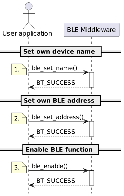
-
Set the name of its own device.
-
Set its own BLE address. The BLE address type is random static type.
-
The BLE function is enabled and the device name and BLE address settings are reflected in the HW.
5.17.2.3. Search for BLE peripheral devices
The BLE scan (search for surrounding BLE peripheral devices) sequence is shown in Figure 98.
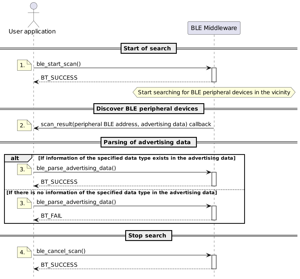
-
Start a BLE scan (search for BLE peripheral devices in the vicinity).
-
If there are any BLE peripheral devices around, callback is called to notify the BLE address of the found device and the advertising data that the found device is sending out.
-
There can be a variety of information in the received data, depending on the configuration of the BLE peripheral device. We have prepared an API, ble_parse_advertising_data(), to retrieve the information your application is looking for from the received data. With this API, you can check the existence of data and values to determine if they meet the conditions you wish to connect to.
-
Stop the search.
5.17.2.4. Connection
The connection sequence is shown in Figure 99.
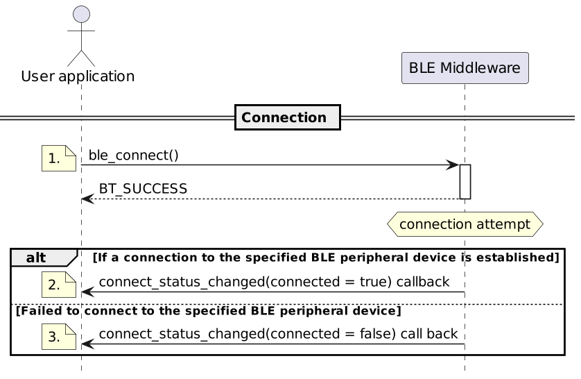
-
Request connection with the BLE address and address type information of the device found by scan_result callback.
-
If a connection is established, the callback function signals bool connected = true. At this time, the structure member ble_connect_handle, the first argument of the callback function, represents the connection identifier, which is required by all APIs used in the connection state and must be remembered. Henceforth, connection identifier is taken to mean the information received here.
-
If the connection could not be made, the callback function will inform bool connected = false.
5.17.2.5. Obtaining service information
The sequence for obtaining service information is shown in Figure 100.
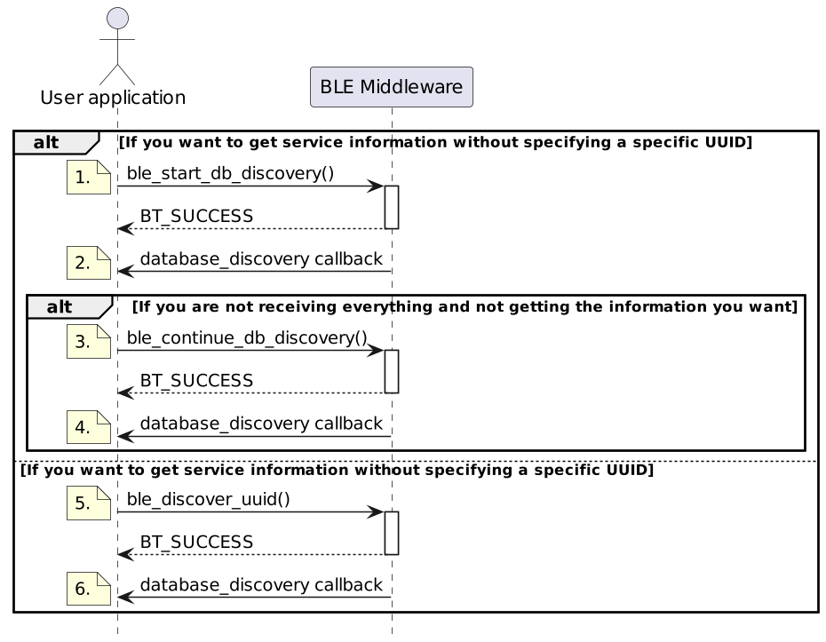
-
If you want to get service information in order from the beginning, run ble_start_db_discovery() with the connection identifier.
-
You will be notified of the list of service information found.
-
If all has not been received, and if the information you want is not among the received data, you can request a continuation with ble_continue_db_discovery().
-
The result of the acquisition is notified by callback as in ble_start_db_discovery().
-
ble_discover_uuid() can be used to retrieve only the information for a given UUID.
-
Even when a UUID is specified, the acquisition result is notified by callback in the same way as in ble_start_db_discovery().
The information obtained includes the following information
-
UUID
-
property (whether or not notify, read, or write permissions are granted)
-
handle(identifier used when sending/receiving data)
5.17.2.6. Encryption of communication channel
The communication channel encryption sequence is shown in Figure 101.
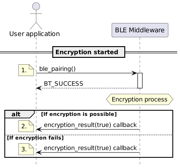
-
Start encryption.
-
If encryption of the communication path between the BLE peripheral and the connection partner is successful, the successful encryption is notified by callback.
-
If encryption of the communication path between the BLE peripheral and the connection partner fails, the encryption failure is notified by callback.
5.17.2.7. Data communication
5.17.2.7.1. Data update
The data update sequence is shown in Figure 102.
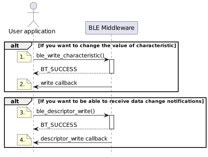
-
For a given connection identifier and a given characteristic identifier, update the value with the specified buffer data.
-
Update results are notified by write callback.
-
To be able to receive data change notifications from the BLE peripheral, specify CCCD in ble_descriptor_write().
-
Update results are notified by descriptor_write callback.
5.17.2.7.2. Data readout
The data read sequence is shown in Figure 103.
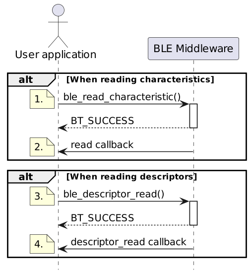
-
Read requests are made for the specified connection identifier and the characteristic identifier.
-
Read results are notified by read callback.
-
Read requests are made for the specified connection identifier and descriptor identifier.
-
Read results are notified by descriptor_read callback.
5.17.2.7.3. Data received
The data reception sequence is shown in Figure 104.
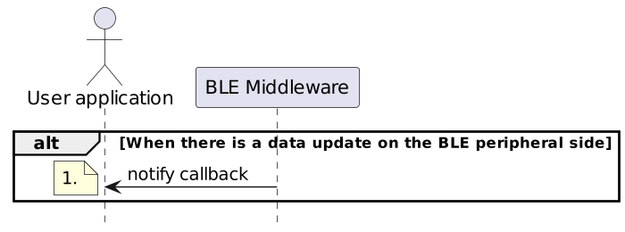
-
When there is a data update on the BLE peripheral side, the updated data is notified by notify callback.
5.17.2.8. Disconnected
The disconnect sequence is shown in Figure 105.
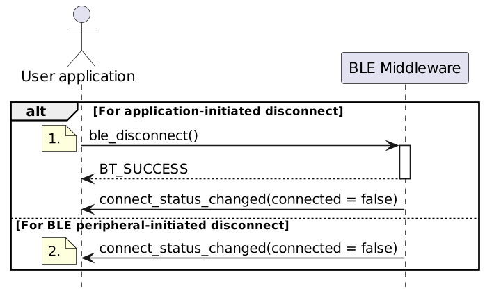
-
For application-initiated disconnection, the connection identifier is specified in ble_disconnect(). When the disconnection is complete, connect_status_changed callback is called with the argument connected = false.
-
If a BLE peripheral-initiated disconnection occurs, simply connect_status_changed callback is called with the argument connected = false.
5.17.3. BLE peripheral
5.17.3.1. Basic flow
When operated as a BLE peripheral, it connects to BLE central and communicates data as follows.
-
initialization
-
Service Configuration
-
Advertise (let surrounding BLE central know of your presence)
-
Connect (wait for BLE central-driven process to connect)
-
Encryption of communication channel (waiting for BLE central initiative to encrypt)
-
data communication
-
disconnection
5.17.3.2. Initialization process
5.17.3.2.1. Initializing BLE Middleware
Initialize the BLE middleware with bt_init().
This is same as BLE central.
5.17.3.2.2. callback function registration
The BLE middleware notifies the user of the results of each API execution and of messages received from the BLE peripheral. This is accomplished by executing a callback function registered by the application.
There are two major groups of callback functions to register.
The functions that share the same type definitions as BLE central are Register with ble_register_common_cb() API.
The structure is of type struct ble_common_ops_s and has the following members
| Registered function | Timing when member functions are called |
|---|---|
connect_status_changed |
when BLE central connects |
scan_result |
Not used in BLE peripheral. |
load_bondinfo |
called before return when bt_enable() is executed. |
saved_bondinfo |
called upon successful pairing. |
encryption_result |
BLE central-driven encryption process. |
BLE peripheral-specific callback functions are registered with the ble_add_characteristic() API used in the service configuration process described below.
The structure is of type struct ble_gatt_peripheral_ops_s and has the following members
| Registered function | Timing when member functions are called |
|---|---|
write |
Called when BLE central updates a characteristic. |
notify |
Called when BLE central updates CCCD. |
The callback function members for unused functions can be set to NULL.
5.17.3.3. Service settings
The service configuration sequence is shown in Figure 106.
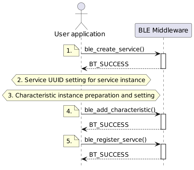
-
Obtain a service instance.
-
Set the UUID to the acquired service instance.
-
Prepare and set up an instance in your application to configure the characteristics you wish to hang on the service.
-
Hanging the specified characteristic instance on the specified service instance.
-
Configure and enable the specified service instance for HW.
The only service setting to be made within the application process is the UUID setting. Set to the member uuid of the instance structure obtained by ble_create_service().
Characteristic settings include attributes, data size, and permissions in addition to UUID.
| member | meaning | how to set |
|---|---|---|
value.len |
data length |
max length. |
value.attrPerm |
attribute |
Set encryption required or not. |
property |
authority |
bit field structure, and the bit of the operation you want to allow is set to 1. |
5.17.3.4. Advertise
Advertising is the act of letting the surrounding BLE central know what kind of device you are, while letting the surrounding BLE central know the presence of your device.
This sequence is shown in Figure 107.
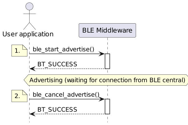
-
Start advertising and be found by surrounding BLE central.
-
Stops advertising and makes the device undetectable to surrounding BLE central.
Thereafter, BLE central will initiate connection and communication channel encryption.
5.17.3.5. Connection
Because BLE central initiates connection, BLE peripheral waits for the connection to be established after the start of the advertisement.
Notification is called by the connect_status_changed() callback in the group of callback functions registered with ble_register_common_ops().
The argument struct ble_state_s *state in the connect_status_changed callback function, The member ble_connect_handle is the connection identifier, Since it is commonly used by all APIs that take place in a connected state It must be memorized by the application.
5.17.3.6. Encryption of communication channel
Because BLE central initiates encryption of the communication channel, BLE peripheral waits for the encryption completion notification after the connection is made.
Notification is called by the encryption_result() callback in the group of callback functions registered with ble_register_common_ops().
5.17.4. Various conditions
6. Functions provided by NuttX
For the functions provided by NuttX, please refer to the NuttX documentation.