
1. Audio Tutorial
The audio library contains a variety of sample sketches, including audio playback and recording.
By taking advantage of the multi-core characteristics of Spresense, codec processing such as audio encoding/decoding is executed by a dedicated core which we call DSP. The audio applications can run without doing the heavy codec processing on the main core.
Audio Tutorial explains how to install DSP files and how to execute various sample sketches.
-
-
Playback system
-
Recording system
-
Composite system
-
-
-
Playback system
-
Recording system
-
Record while listening to the input from the microphone
-
Process audio and output
-
1.1. Install DSP files
When running the sample, it is necessary to install the DSP file in advance for decoder if use audio playback or encoder if you use audio recorder. This section describes how to install the DSP file.
1.1.1. DSP file type
| DSP file name | DSP installer | Description |
|---|---|---|
MP3DEC |
mp3_dec_installer |
Used for MP3 audio playback |
MP3ENC |
mp3_enc_installer |
Used for MP3 audio recording |
WAVDEC |
wav_dec_installer |
Used for WAV (PCM) audio playback |
SRC |
src_installer |
Use for WAV(PCM) audio recording |
1.1.2. How to install DSP
There are two ways to install DSP.
-
How to download DSP file and copy directly to microSD card
-
Using the DSP installer sketch
You can use either method when installing to a microSD card. When using the DSP installer, it is possible to install it on the SPI-Flash on the main board in addition to the microSD card on the extension board.
| The DSP needs to be install once, you only need to re install it if the DSP file is updated. |
1.1.2.1. How to install by copying DSP file to microSD card
Download the latest DSP file from here.
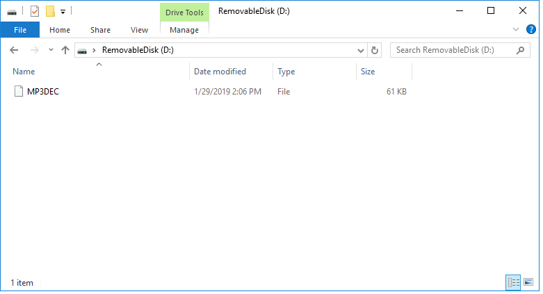
Please insert this microSD card into the extension board and run it when you want to execute the audio samples.
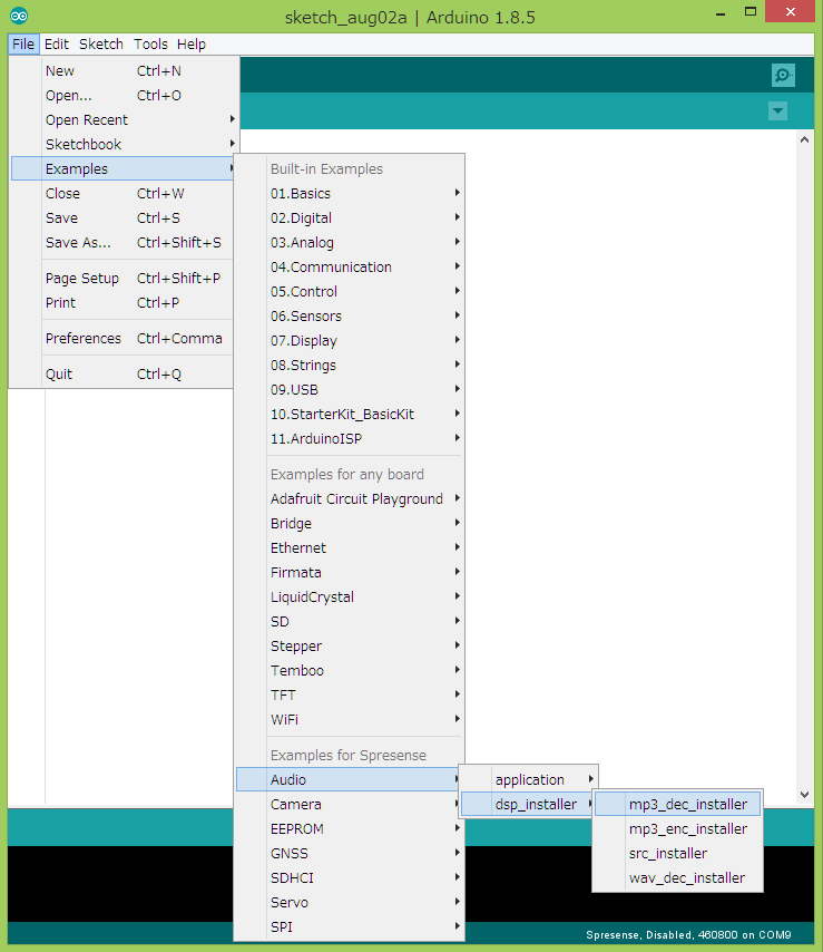
1.1.2.2. How to install using DSP installer
A DSP installer is provided for each DSP file you install.
-
From the Arduino IDE, start from
File → Examples → Examples for Spresense / Audio → dsp_installer. Figure 2. Starting the DSP installer
 -
Select the COM port of Spresense in
Tools → Portand execute writing. -
When the compilation & writing (Upload) is completed, start the serial monitor.
-
If you select a baud rate of 115200 bps, a message will appear as shown in the figure below.
-
Select the number that you want to install and press the send button.
When installing to a microSD card, insert a FAT32 formatted microSD card into the microSD card slot on the extension board. Figure 3. Select DSP installation location
 -
If the installation is successful, the message shown below is displayed.
 Figure 4. DSP installation execution


In the audio playback/recording application program, the location where the DSP file is installed is specified by the argument of the initPlayer() function or the initRecorder() function.
By default, a microSD card (/mnt/sd0/BIN) is specified. When changing to SPI-Flash, rewrite to /mnt/spif/BIN.
|
1.2. High-level interface layer
Spresense Audio library has a layer structure as described in Audio library development guide.
In the high-level interface layer, typical functions with a high degree of abstraction are supported while maintaining the consistency of the entire system.
Below is a sample using this high-level interface layer.
1.2.1. Make a beep
1.2.1.1. Overview
This sample uses the capabilities of the Audio hardware to emit a beep.
Output the sound of the specified frequency with the setBeep() function of the Audio library.
This function is very similar to Arduino’s tone() function, but it does not require a piezoelectric buzzer.
Sound is output from the headphone terminal of the Spresense extension board.
In this sample, it is not necessary to install the DSP file.
1.2.1.2. Operating environment
-
Spresense Main & Extension Board
-
Playback headphones or speakers
Connect headphones or active speakers to the headphone jack on the extension board.
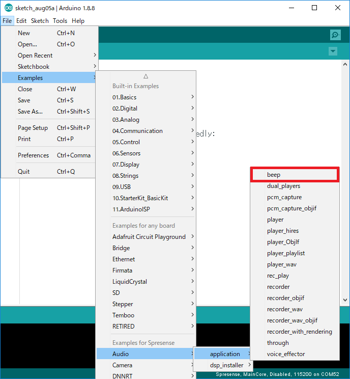
1.2.1.3. Operating procedure
-
Open the sample sketch by selecting
File → Examples → Example for Spresense / Audio → application → beepfrom Arduino IDE.
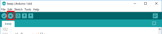
Select the COM port of Spresense with Tools → Port and write to the microcomputer board.
The scale of Do-re-mi-fa-so-la-ti-do is output from the headphones.
1.2.1.4. Program description
-
Set the player mode with the
setPlayerMode()function.theAudio->setPlayerMode(device, (1) player0bufsize, (2) player1bufsize); (3)1 device: Select the output device, whether to output to speaker headphones (AS_SETPLAYER_OUTPUTDEVICE_SPHP) or I2S (AS_SETPLAYER_OUTPUTDEVICE_I2SOUTPUT).
This sample usesAS_SETPLAYER_OUTPUTDEVICE_SPHP.
When using I2S, refer to How to output to I2S.2 player0bufsize: Specifies the buffer size of player 0.3 player1bufsize: Specifies the buffer size of player 1.
For details, refer to Player buffer size.
The buffer is not used if only the beep sound is output, so 0 is specified in this sample. -
To output the beep sound, use the
setBeep()function.theAudio->setBeep(enable, (1) volume, (2) frequency); (3)1 If you set enableto 1, the beep sound will be output, and if enable is set to0, the output will stop.2 volume: You can change the volume (-90 ~ 0 [dB]).3 frequency: Outputs the sound of the specified frequency.
1.2.2. Play MP3 music
1.2.2.2. Operating environment
-
Spresense Main & Extension Board
-
microSD card
-
Playback headphones or speakers
This sample uses a microSD card and headphones. Connect headphones or active speakers to the headphone jack on the extension board.
1.2.2.3. Operating procedure
-
Install the DSP file
MP3DECfor MP3 decoding to the microSD card (see Install DSP files). -
Put on the MP3 file you want to play with the file name "Sound.mp3" in the root directory of the microSD card.
-
Insert the microSD card into the microSD card slot on the extension board.
-
Open the sample sketch by selecting
File → Examples → Examples for Spresense / Audio → application → playerfrom Arduino IDE.

Select the COM port of Spresense with Tools → Port and write to the microcomputer board.
When the sketch is uploaded and executed, the MP3 file placed on the microSD card will be played via headphone.
Play the file to the end and stop.
1.2.2.4. Program description
-
Set the clock mode with the
setRenderingClockMode()function.theAudio->setRenderingClockMode(mode); (1)1 mode: Select normal (AS_CLKMODE_NORMAL) or high resolution (AS_CLKMODE_HIRES) or clock mode.
For MP3 playback, specifyAS_CLKMODE_NORMAL. -
Set the player mode with the
setPlayerMode()function.theAudio->setPlayerMode(device, (1) sp_drv); (2)1 device: Select the output device, whether to output to speaker headphones (AS_SETPLAYER_OUTPUTDEVICE_SPHP) or I2S (AS_SETPLAYER_OUTPUTDEVICE_I2SOUTPUT).
This sample usesAS_SETPLAYER_OUTPUTDEVICE_SPHP.
When using I2S, refer to How to output to I2S.2 sp_drv: Sets the output drive.
In this sample, specifyAS_SP_DRV_MODE_LINEOUT.
For details, refer to When using the speaker terminal of the extension board. -
Initialize the player with the
initPlayer()function.theAudio->initPlayer(id, (1) codec, (2) codec_path, (3) fs, (4) channel); (5)1 id: Select Player ID.
This sample usesAudioClass::Player0.2 codec: Specify MP3 (AS_CODECTYPE_MP3) as the codec type.3 codec_path: Specify the location where the DSP file is installed.
Specify "/mnt/sd0/BIN" for microSD card and "/mnt/spif/BIN" for SPI-Flash.4 fs: Specify the sampling rate.
MP3 supports 32kHz (AS_SAMPLINGRATE_32000), 44.1kHz (AS_SAMPLINGRATE_44100), 48kHz (AS_SAMPLINGRATE_48000). If you specifyAS_SAMPLINGRATE_AUTO, the sampling rate is automatically determined.5 channel: Specify monaural (AS_CHANNEL_MONO) or stereo (AS_CHANNEL_STEREO). -
Write the contents of the MP3 file to the decoder with the
writeFrames()function.theAudio->writeFrames(id, (1) myFile); (2)1 id: Select Player ID.
This sample usesAudioClass::Player0.2 You can change the playback file by specifying myFile in the argument.
This sample uses a file called "Sound.mp3".
Execute this function periodically to supply the stream to the decoder so that the decoding will not be interrupted. When writing the file is completed,AUDIOLIB_ECODE_FILEENDis returned as the return value of the function. -
Start the player with the
startPlayer()function.theAudio->startPlayer(id); (1)1 id: Select Player ID.
This sample usesAudioClass::Player0.
Call it after writing to the decoder with thewriteFrames()function. -
Stop the player with the
stopPlayer()function.theAudio->stopPlayer(id, (1) mode); (2)1 id: Select Player ID.
This sample usesAudioClass::Player0.2 You can choose to stop immediately in mode(AS_STOPPLAYER_NORMAL) or wait until the stream supplied to the decoder has finished playing and then stop (AS_STOPPLAYER_ESEND). If called without themodeargument, it works withAS_STOPPLAYER_NORMAL. -
Adjust the volume with the
setVolume(volume)function.theAudio->setVolume(volume); (1)1 volume: You can change the volume. (-1020 ~ 120)
1/10 of the specified value becomes the actual volume [dB]. For example, the volume when 15 is specified, is 1.5 [dB].
1.2.2.5. Player buffer size
A buffer size of 160kByte to use for reading from the microSD card is secured by default for each player. This size is such that high resolution WAV audio can be read, and when playing a 48 kHz MP3 file or etc, you can reduce the buffer size used in the argument of the setPlayerMode function. As a guideline, when playing a 192kHz high resolution WAV file, it needs the 160kByte which is default, and it is recommended to set it to about 24kByte when playing an MP3 file of about 128kbps.
| Regarding the size, it is a suggestion only. Adjust according to the performance of the microSD card and the processing amount of the application. If you make the buffer too small, you will get errors when reading from the microSD card. If read data underflow occurs, increase the buffer size. |
1.2.2.6. How to output to I2S
If you want to switch the output device to I2S, switch the output device with setPlayerMode to AS_SETPLAYER_OUTPUTDEVICE_I2SOUTPUT. The I2S operation mode supports only Slave mode, I2S format mode, 48000Hz, and Stereo.
1.2.2.7. When using the speaker terminal of the extension board
In the case of line-out using the headphone terminal of the extension board as the audio output destination, as the drive capability setting of Audio signal,
Specify AS_SP_DRV_MODE_LINEOUT as the argument sp_drv of setPlayerMode (default).
When outputting from the speaker terminal of the extension board, specify AS_SP_DRV_MODE_4DRIVER in the argument sp_drv.
When using the speaker terminal, the board needs to be modified. For details, refer to the following hardware guide.
| MP3 files have ID3v2 TAGs (especially large metadata like image data) will cause parse errors by the decoder. |
Please delete the tag information with some tool.
1.2.3. Play WAV music
1.2.3.2. Operating environment
-
Spresense Main & Extension Board
-
microSD card
-
Playback headphones or speakers
This sample uses a microSD card and headphones. Connect headphones or active speakers to the headphone jack on the extension board.
1.2.3.3. Operating procedure
-
Install the DSP file
WAVDECfor WAV decoding to the microSD card (see Install DSP files). -
Put on the WAV file you want to play with the file name "Sound.wav" in the root directory of the microSD card.
-
Insert the microSD card into the microSD card slot on the extension board.
-
Open the sample sketch by selecting
File → Examples → Examples for Spresense / Audio → application → player_wavfrom Arduino IDE.
-
Select the COM port of Spresense with
Tools → Portand write to the microcomputer board. -
When the sketch is uploaded and executed, the WAV file placed on the microSD card will be played via headphone.
Play the file to the end and stop.

1.2.3.4. Program description
-
Set the clock mode with the
setRenderingClockMode()function.theAudio->setRenderingClockMode(mode); (1)1 mode: Select normal (AS_CLKMODE_NORMAL) or high resolution (AS_CLKMODE_HIRES) or clock mode.
This sample usesAS_CLKMODE_NORMAL.
This function only accepts before callingsetPlayerMode()or in ReadyMode.
To switch between normal and high resolution dynamically, callsetReadyMode()and transition to the Ready state, then switchAS_CLKMODE_NORMALorAS_CLKMODE_HIRES. -
Set the player mode with the
setPlayerMode()function.theAudio->setPlayerMode(device, (1) sp_drv); (2)1 device: Select the output device, whether to output to speaker headphones (AS_SETPLAYER_OUTPUTDEVICE_SPHP) or I2S (AS_SETPLAYER_OUTPUTDEVICE_I2SOUTPUT).
This sample usesAS_SETPLAYER_OUTPUTDEVICE_SPHP.
When using I2S, refer to How to output to I2S.2 sp_drv: Sets the output drive.
In this sample, specifyAS_SP_DRV_MODE_LINEOUT.
For details, refer to When using the speaker terminal of the extension board. -
Initialize the player with the
initPlayer()function.theAudio->initPlayer(id, (1) codec, (2) codec_path, (3) fs, (4) channel); (5)1 id: Select Player ID.
This sample usesAudioClass::Player0.2 codec: Specify WAV (AS_CODECTYPE_WAV) as the codec type.3 codec_path: Specify the location where the DSP file is installed.
Specify "/mnt/sd0/BIN" for microSD card and "/mnt/spif/BIN" for SPI-Flash.4 fs: Specify the sampling rate.
5 channel: Specify monaural (AS_CHANNEL_MONO) or stereo (AS_CHANNEL_STEREO). -
Write the contents of the WAV file to the decoder with the
writeFrames()function.theAudio->writeFrames(id, (1) myFile); (2)1 id: Select Player ID.
This sample usesAudioClass::Player0.2 You can change the playback file by specifying myFile in the argument.
This sample uses a file called "Sound.wav".
Execute this function periodically to supply the stream to the decoder so that the decoding will not be interrupted. When writing the file is completed,AUDIOLIB_ECODE_FILEENDis returned as the return value of the function. -
Start the player with the
startPlayer()function.theAudio->startPlayer(id); (1)1 id: Select Player ID.
This sample usesAudioClass::Player0.
Call it after writing to the decoder with thewriteFrames()function. -
Stop the player with the
stopPlayer()function.theAudio->stopPlayer(id, (1) mode); (2)1 id: Select Player ID.
This sample usesAudioClass::Player0.2 You can choose to stop immediately in mode(AS_STOPPLAYER_NORMAL) or wait until the stream supplied to the decoder has finished playing and then stop (AS_STOPPLAYER_ESEND). If called without themodeargument, it works withAS_STOPPLAYER_NORMAL. -
Adjust the volume with the
setVolume(volume)function.theAudio->setVolume(volume); (1)1 volume: You can change the volume. (-1020 ~ 120)
1/10 of the specified value becomes the actual volume [dB]. For example, the volume when 15 is specified, is 1.5 [dB].
1.2.4. Play high resolution audio
1.2.4.2. Operating environment
-
Spresense Main & Extension Board
-
microSD card
-
Playback headphones or speakers
This sample uses a microSD card and headphones. Connect headphones or active speakers to the headphone jack on the extension board.
1.2.4.3. Operating procedure
Install the DSP file WAVDEC for WAV decoding to the microSD card (see Install DSP files).
Put on the WAV file you want to play and rename the file name to "HiResSound.wav" in the root directory of the microSD card.
-
Insert the microSD card into the microSD card slot on the extension board.
-
Open the sample sketch by selecting
File → Examples → Examples for Spresense / Audio → application → player_hiresfrom Arduino IDE.
-
Select the COM port of Spresense with
Tools → Portand write to the microcomputer board. -
When the sketch is uploaded and executed, the WAV file of high-resolution sound placed on the microSD card will be played via headphone.
Play the file to the end and stop.

1.2.4.4. Program description
-
Set the clock mode with the
setRenderingClockMode()function.theAudio->setRenderingClockMode(mode); (1)1 mode: Select normal (AS_CLKMODE_NORMAL) or high resolution (AS_CLKMODE_HIRES) or clock mode.
This sample usesAS_CLKMODE_NORMAL.
setPlayerMode()can be called only inReadyMode.
To switch between normal and high resolution dynamically, callsetReadyMode()and transition to the Ready state, then switchAS_CLKMODE_NORMALorAS_CLKMODE_HIRES. -
Set the player mode with the
setPlayerMode()function.theAudio->setPlayerMode(device, (1) sp_drv); (2)1 device: Select the output device, whether to output to speaker headphones (AS_SETPLAYER_OUTPUTDEVICE_SPHP) or I2S (AS_SETPLAYER_OUTPUTDEVICE_I2SOUTPUT).
This sample usesAS_SETPLAYER_OUTPUTDEVICE_SPHP.
When using I2S, refer to How to output to I2S.2 sp_drv: Sets the output drive.
In this sample, specifyAS_SP_DRV_MODE_LINEOUT.
For details, refer to When using the speaker terminal of the extension board. -
Initialize the player with the
initPlayer()function.theAudio->initPlayer(id, (1) codec, (2) codec_path, (3) fs, (4) bitlen, (5) channel); (6)1 id: Select Player ID.
This sample usesAudioClass::Player0.2 codec: Specify WAV (AS_CODECTYPE_WAV) as the codec type.3 codec_path: Specify the location where the DSP file is installed.
Specify "/mnt/sd0/BIN" for microSD card and "/mnt/spif/BIN" for SPI-Flash.4 fs: Specify the sampling rate.
In this sample, 96kHz (AS_SAMPLINGRATE_96000) is specified.5 bitlen: Specify the bit length.
In this sample, 24bit (AS_BITLENGTH_24) is specified.6 channel: Specify monaural (AS_CHANNEL_MONO) or stereo (AS_CHANNEL_STEREO). -
Write the contents of the WAV file to the decoder with the
writeFrames()function.theAudio->writeFrames(id, (1) myFile); (2)1 id: Select Player ID.
This sample usesAudioClass::Player0.2 You can change the playback file by specifying myFile in the argument.
This sample uses a file called "HiResSound.wav".
Execute this function periodically to supply the stream to the decoder so that the decoding will not be interrupted. When writing the file is completed,AUDIOLIB_ECODE_FILEENDis returned as the return value of the function. -
Start the player with the
startPlayer()function.theAudio->startPlayer(id); (1)1 id: Select Player ID.
This sample usesAudioClass::Player0.
Call it after writing to the decoder with thewriteFrames()function. -
Stop the player with the
stopPlayer()function.theAudio->stopPlayer(id, (1) mode); (2)1 id: Select Player ID.
This sample usesAudioClass::Player0.2 You can choose to stop immediately in mode(AS_STOPPLAYER_NORMAL) or wait until the stream supplied to the decoder has finished playing and then stop (AS_STOPPLAYER_ESEND). If called without themodeargument, it works withAS_STOPPLAYER_NORMAL. -
Adjust the volume with the
setVolume(volume)function.theAudio->setVolume(volume); (1)1 volume: You can change the volume. (-1020 ~ 120)
1/10 of the specified value becomes the actual volume [dB]. For example, the volume when 15 is specified, is 1.5 [dB].
1.2.5. Play Playlist of music
1.2.5.1. Overview
This sample is a sample sketch for playing music using a playlist.
Plays multiple music files in the microSD card in order. You can perform operations such as play, stop, send to next song, return, repeat play and random play.
1.2.5.2. Operating environment
-
Spresense Main & Extension Board
-
microSD card
-
Playback headphones or speakers
This sample uses a microSD card and headphones. Connect headphones or active speakers to the headphone jack on the extension board.
1.2.5.3. Program description
In order to use the playlist function, it is necessary to create a playlist file on a PC beforehand and copy it to the microSD card. The directory structure of the microSD card used in this sample sketch is shown below.
microSD card root directory
|-- BIN/
|   |-- MP3DEC
|   `-- WAVDEC
|-- AUDIO/
|   |-- Sound1.mp3
|   |-- Sound2.mp3
|   |--   :
|   |-- Sound1.wav
|   |-- Sound2.wav
|   |--   :
`-- PLAYLIST/
`-- TRACK_DB.CSV-
Install the
MP3DECandWAVDECDSP binary files in the BIN/ directory (see Install DSP files). -
Copy the music content files to play in the playlist to the AUDIO/ directory.
-
Copy the playlist file (
TRACK_DB.CSV) to the PLAYLIST/ directory.
How to create a playlist file
The format of the playlist file TRACK_DB.CSV is shown below.
It is the text file in CSV (comma-separated values) format and in which the information of each file is written in line units.
[filename],[artist],[album],[channel number],[bit length],[sampling rate],[file format]
[filename],[artist],[album],[channel number],[bit length],[sampling rate],[file format]
[filename],[artist],[album],[channel number],[bit length],[sampling rate],[file format]
 :
Please describe the file name, artist name, album name, and codec information (number of channels, bit length, sampling rate) of the music contents.
An example of TRACK_DB.CSV is shown below.
Sound1.mp3,Artist1,Album1,2,16,44100,mp3
Sound2.mp3,Artist1,Album1,2,16,44100,mp3
Sound1.wav,Artist2,Album2,2,16,48000,wav
Sound2.wav,Artist2,Album2,2,24,192000,wav
We also provide a simple script tool, mkplaylist.py, for creating playlist files. Please right-click here and download the file. This script uses ffmpeg-python, so please use it with ffmpeg and ffmpeg-python installed.
The usage of mkplaylist.py is shown below.
python mkplaylist.py
usage: python mkplaylist.py dirname [dirname2] [dirname3] ...
usage: python mkplaylist.py -f filename

Generate an audio playlist file named as TRACK_DB.CSV
Please execute by specifying the directory path containing the music file as an argument. When the execution is completed normally, the TRACK_DB.CSV file will be output to the current directory. If the TRACK_DB.CSV file already exists, it will be added to the end of the file.
python mkplaylist.py MyMusic
|
-
Open the sample sketch by selecting
File → Examples → Examples for Spresense / Audio → application → play_playlistfrom Arduino IDE.
-
Select the COM port of Spresense with
Tools → Portand write to the microcomputer board. -
When you start the serial monitor, the following menu is displayed. Various operations are performed according to the key input from the serial.

=== MENU (input key ?) ==============
p: play  s: stop  +/-: volume up/down
l: list  n: next  b: back
r: repeat on/off  R: random on/off
a: auto play      m,h,?: menu
=====================================| The EEPROM library is used to save setting information such as volume value, random / repeat / auto play, etc. in non-volatile memory. It is a sample application that operates based on the previously preset information at the next startup. Please refer to it when creating your own music player. |
1.2.6. Play dual MP3 music
1.2.6.2. Operating environment
-
Spresense Main & Extension Board
-
microSD card
-
Playback headphones or speakers
This sample uses a microSD card and headphones. Connect headphones or active speakers to the headphone jack on the extension board.
1.2.6.3. Operating procedure
-
Install the DSP file
MP3DECfor MP3 decoding to the microSD card (see Install DSP files). -
Put the two MP3 files you want to play in the root directory of the microSD card with the file names "Sound0.mp3" and "Sound1.mp3".
-
Insert the microSD card into the microSD card slot on the extension board.
-
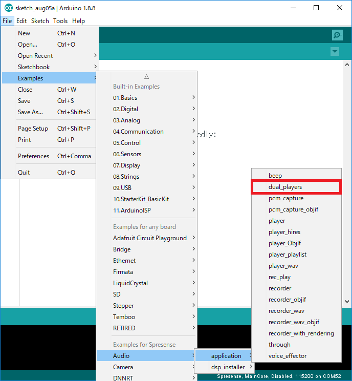
Open the sample sketch by selecting
File → Examples → Examples for Spresense / Audio → application → dual_playersfrom Arduino IDE.
-
Select the COM port of Spresense with
Tools → Portand write to the microcomputer board. -
Once the sketch is uploaded and executed, the two MP3 files placed on the microSD card will be mixed and played from the line-out at the same time. Play each file repeatedly.
1.2.6.4. Program description
-
Set the clock mode with the
setRenderingClockMode()function.theAudio->setRenderingClockMode(mode); (1)1 mode: Select normal (AS_CLKMODE_NORMAL) or high resolution (AS_CLKMODE_HIRES) or clock mode.
For MP3 playback, specifyAS_CLKMODE_NORMAL. -
Set the player mode with the
setPlayerMode()function.theAudio->setPlayerMode(device, (1) sp_drv); (2)1 device: Select the output device, whether to output to speaker headphones (AS_SETPLAYER_OUTPUTDEVICE_SPHP) or I2S (AS_SETPLAYER_OUTPUTDEVICE_I2SOUTPUT).
This sample usesAS_SETPLAYER_OUTPUTDEVICE_SPHP.
When using I2S, refer to How to output to I2S.2 sp_drv: Sets the output drive.
In this sample, specifyAS_SP_DRV_MODE_LINEOUT.
For details, refer to When using the speaker terminal of the extension board. -
Initialize the player with the
initPlayer()function for players 0 and 1 respectively.theAudio->initPlayer(id, (1) codec, (2) codec_path, (3) fs, (4) channel); (5)1 id: Select Player ID.
One specifiesAudioClass::Player0and the other specifiesAudioClass::Player1.2 codec: Specify MP3 (AS_CODECTYPE_MP3) as the codec type.3 codec_path: Specify the location where the DSP file is installed.
Specify "/mnt/sd0/BIN" for microSD card and "/mnt/spif/BIN" for SPI-Flash.4 fs: Specify the sampling rate.
MP3 supports 32kHz (AS_SAMPLINGRATE_32000), 44.1kHz (AS_SAMPLINGRATE_44100), 48kHz (AS_SAMPLINGRATE_48000). If you specifyAS_SAMPLINGRATE_AUTO, the sampling rate is automatically determined.5 channel: Specify monaural (AS_CHANNEL_MONO) or stereo (AS_CHANNEL_STEREO). -
Write the MP3 file contents to the decoder with the
writeFrames()function for players 0 and 1, respectively.theAudio->writeFrames(id, (1) myFile); (2)1 id: Select Player ID.
One specifiesAudioClass::Player0and the other specifiesAudioClass::Player1.2 You can change the playback file by specifying myFile in the argument.
This sample uses files called "Sound0.mp3" and "Sound1.mp3".
Execute this function periodically to supply the stream to the decoder so that the decoding will not be interrupted. When writing the file is completed,AUDIOLIB_ECODE_FILEENDis returned as the return value of the function. -
Start the player with the
startPlayer()function for each of players 0 and 1.theAudio->startPlayer(id); (1)1 id: Select Player ID.
One specifiesAudioClass::Player0and the other specifiesAudioClass::Player1.
Call it after writing to the decoder with thewriteFrames()function. -
Stop the player with the
stopPlayer()function for each of players 0 and 1.theAudio->stopPlayer(id, (1) mode); (2)1 id: Select Player ID.
One specifiesAudioClass::Player0and the other specifiesAudioClass::Player1.
2 You can choose to stop immediately in mode(AS_STOPPLAYER_NORMAL) or wait until the stream supplied to the decoder has finished playing and then stop (AS_STOPPLAYER_ESEND). If called without themodeargument, it works withAS_STOPPLAYER_NORMAL. -
Adjust the volume with the
setVolume(master, player0, player1)function.theAudio->setVolume(master, (1) player0, (2) player1); (3)1 master: You can change the volume for both players 0 and 1. (-1020 ~ 120)2 You can change the volume for player 0 with player0. (-1020 ~ 120)3 You can change the volume for player 1 with player1. (-1020 ~ 120)
1/10 of the specified value becomes the actual volume [dB]. For example, the volume when 15 is specified, is 1.5 [dB]. You can adjust the overall volume withmasterand the individual volume withplayer0andplayer1.
1.2.7. Listen to the sound input from the microphone
1.2.7.1. Overview
You can hear the sound from the microphone from the headphone jack by using the audio path setting function of Audio HW.
For example, to output digital audio input from I2S to analog, or such as outputting the input from the microphone to I2S it is possible. This function supports an output mechanism that saves power and has very low latency.
1.2.7.2. Operating environment
-
Spresense Main & Extension Board
-
Playback headphones or speakers
-
Recording microphone
In this sample, headphones and a microphone are used. Connect headphones or active speakers to the headphone jack on the extension board. Please refer to the following hardware guide for microphone connection.
In this sample, it is not necessary to install the DSP file.
1.2.7.3. Operating procedure
-
Open the sample sketch by selecting
File → Examples → Examples for Spresense Audio → application → throughfrom Arduino IDE.
-
The sample sketch outputs the sound input from I2S to the headphone terminal.
Here, change the sketch so that the sound input from the microphone is output to the headphone jack.
Save it in an editable location by doingFile → Save As. -
Change the argument
inputof thesetThroughMode()function fromAudioClass::I2sIntoAudioClass::MicInand save. -
Select the COM port of Spresense with
Tools → Portand write to the microcomputer board. -
Once the sketch is uploaded and executed, you will hear the sound coming from the microphone in your headphones.

1.2.7.4. Program description
-
To set the through mode, use the
setThroughMode()function.theAudio->setThroughMode(input, (1) i2s_out, (2) sp_out, (3) input_gain, (4) sp_drv); (5)1 Select the input system with input.2 Select the source to output to I2S with i2s_out.3 Select whether to output to the headphone speaker with sp_out.
For example, to output the audio input from the microphone to I2S, use
SpecifyAudioClass::MicInforinput,
SpecifyAudioClass::Micini2s_out,
Specifyfalseinsp_out.4 Set the microphone gain with input_gain.
The range is 0 to 21 [dB] for analog microphones and -78.5 to 0 [dB] for digital microphones.
For an analog microphone, specify an integer value multiplied by 10 for input_gain, for example, 100 when setting 10 [dB].
For a digital microphone, specify an integer value multiplied by 100 for input_gain, for example -5 when setting -0.05 [dB].5 For sp_drv, refer to When using the speaker terminal of the extension board.
1.2.8. Record in MP3 format
1.2.8.2. Operating environment
-
Spresense Main & Extension Board
-
Playback headphones or speakers
-
Recording microphone
In this sample, headphones and a microphone are used. Connect headphones or active speakers to the headphone jack on the extension board. Please also refer to the following hardware guide for microphone connection.
1.2.8.3. Operating procedure
-
Install the DSP file
MP3ENCfor MP3 encoding to the microSD card (see Install DSP files). -
Open the sample sketch by selecting
File → Examples →Examples for Spresense Audio → application → recorderon the Arduino IDE.
-
Select the COM port of Spresense with
Tools → Portand write to the microcomputer board. -
Once the sketch is uploaded and executed, recording will start and stop recording after a certain period of time.
-
The recorded data is saved in the microSD card with the file name "Sound.mp3".
Take out the microSD card and check the data recorded on the PC.

1.2.8.4. Program description
-
Set the recorder mode with the
setRecorderMode()function.theAudio->setRecorderMode(input_device, (1) input_gain, (2) bufsize, (3) is_digital); (4)1 input_device: Input from the microphone (AS_SETRECDR_STS_INPUTDEVICE_MIC) as the input device.2 Set the microphone gain with input_gain.
The range is 0 to 21 [dB] for analog microphones and -78.5 to 0 [dB] for digital microphones.
For an analog microphone, specify an integer value multiplied by 10 for input_gain, for example, 100 when setting 10 [dB].
For a digital microphone, specify an integer value multiplied by 100 for input_gain, for example -5 when setting -0.05 [dB].3 bufsize: Specify the buffer size of the recorder.
For details, refer to Recorder buffer size.4 If the connected microphone is a digital microphone, specify truein the argumentis_digital. -
Initialize the recorder with the
initRecorder()function.theAudio->initRecorder(codec, (1) codec_path, (2) fs, (3) channel); (4)1 Specify MP3 ( AS_CODECTYPE_MP3) as the codec type ofcodec.2 Specify the location where the DSP file is installed with codec_path.
Specify "/mnt/sd0/BIN" for microSD card and "/mnt/spif/BIN" for SPI-Flash.3 Specify the sampling rate with fs.
MP3 supports 32kHz (AS_SAMPLINGRATE_32000), 44.1kHz (AS_SAMPLINGRATE_44100), 48kHz (AS_SAMPLINGRATE_48000).4 channel: Specify monaural (AS_CHANNEL_MONO) or stereo (AS_CHANNEL_STEREO). -
Read MP3 encoded data for recording to a file with the
readFrames()function.theAudio->readFrames(myFile); (1)1 The file to be recorded can be changed with the specified myFile.
This sample write to a file called "Sound.mp3".
Execute this function periodically to read the encoding result so that the encoding buffer does not overflow. -
Start the recorder with the
startRecorder()function. -
Stop the recorder with the
stopRecorder()function.
1.2.8.5. Recorder buffer size
The default buffer size used for writing to the microSD card is 160kByte. This size is a size that can write high resolution WAV audio enough, but this memory size is too large for playing a 48 kHz MP3 file, so memory is wasted.
Therefore, when recording a 48kHz MP3 file, You can change the buffer size by setRecorderMode. As a guide, the default 160 kByte is when playing a 192 kHz high resolution WAV file, and when recording a 48 kHz MP3 file, it is recommended to set it to about 8 kByte.
| Regarding size, it is a guide only. Adjust according to the performance of the microSD card and the processing amount of the application. If you make the buffer too small, you will get errors when writing to the microSD card. If overflow occurs, increase the buffer size. |
| Even if audio is obtained, it may not be possible to write all the data due to factors such as the writing performance of the microSD card and the applications that are running. In the case of the current extension board, the limit is 8ch/48kHz or 2ch/192kHz. It also depends on the speed class of the microSD card, so please use the one with the highest transfer rate possible. |
1.2.9. Record in WAV format
1.2.9.2. Operating environment
-
Spresense Main & Extension Board
-
Playback headphones or speakers
-
Recording microphone
In this sample, headphones and a microphone are used. Connect headphones or active speakers to the headphone jack on the extension board. Please refer to the following hardware guide for microphone connection.
1.2.9.3. Operating procedure
-
Install the DSP file
SRCfor WAV(PCM) encoding to the microSD card (see Install DSP files). -
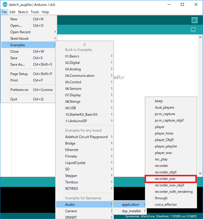
Open the sample sketch by selecting
File → Examples →Examples for Spresense Audio → application → recorder_wavon the Arduino IDE.
-
Select the COM port of Spresense with
Tools → Portand write to the microcomputer board. -
Once the sketch is uploaded and executed, recording will start and stop recording after a certain period of time.
-
The recorded data is saved in the microSD card with the file name "Sound.wav".
Take out the microSD card and check the data recorded on the PC.
1.2.9.4. Program description
-
Set the recorder mode with the
setRecorderMode()function.theAudio->setRecorderMode(input_device, (1) input_gain, (2) bufsize, (3) is_digital); (4)1 input_device: Input from the microphone (AS_SETRECDR_STS_INPUTDEVICE_MIC) as the input device.2 Set the microphone gain with input_gain.
The range is 0 to 21 [dB] for analog microphones and -78.5 to 0 [dB] for digital microphones.
For an analog microphone, specify an integer value multiplied by 10 for input_gain, for example, 100 when setting 10 [dB].
For a digital microphone, specify an integer value multiplied by 100 for input_gain, for example -5 when setting -0.05 [dB].3 bufsize: Specify the buffer size of the recorder.
For details, refer to Recoder buffer size.4 If the connected microphone is a digital microphone, specify truein the argumentis_digital. -
Initialize the recorder with the
initRecorder()function.theAudio->initRecorder(codec, (1) codec_path, (2) fs, (3) channel); (4)1 Specify WAV ( AS_CODECTYPE_WAV) as the codec type ofcodec.2 Specify the location where the DSP file is installed with codec_path.
Specify "/mnt/sd0/BIN" for microSD card and "/mnt/spif/BIN" for SPI-Flash.3 Specify the sampling rate with fs.4 channel: Specify the number of channels(upto 8 channels).
When recording at high resolution (192kHz, 24bit), fs is AS_SAMPLINGRATE_192000 and bitlen is AS_BITLENGTH_24.
|
+
theAudio->initRecorder(codec,
                       codec_path,
                       fs,
                       bitlen,
channel);-
When recording a WAV file, call the
writeWavHeader()function to create a WAV header before executing the audio recording.theAudio->writeWavHeader(myFile); (1)1 Specify the file to record.
This sample uses a file called "Sound.wav". -
The
readFrames()function reads WAV (PCM) encoded data for recording to a file.theAudio->readFrames(myFile); (1)1 You can change the file to be recorded by specifying myFile.
This sample uses a file called "Sound.wav".
Please execute this function periodically to read the encoding result so that the encoding buffer does not overflow.
1.2.9.5. About recorder buffer size
See Recorder buffer size.
1.2.9.6. If recording fails
Depending on the state of the microSD, the manufacturer, etc., recording may fail even with the default buffer size. In that case, secure a larger buffer size for writing.
You can change the buffer size used with setRecorderMode . When performing 8-channel recording, high-resolution stereo recording, etc., increasing the size to about 500 kB will result in fairly stable recording operation.
However, in that case, the memory area for MainCore will be insufficient, so select Tools→ Memory→ 1024KB from the Arduino IDE to secure the memory area.
example.)
/* Select input device as microphone */
  theAudio->setRecorderMode(AS_SETRECDR_STS_INPUTDEVICE_MIC);
⇒
/* Select input device as microphone */
  theAudio->setRecorderMode(AS_SETRECDR_STS_INPUTDEVICE_MIC, "microphone gain" ,(500*1024));
1.2.10. Retrieve PCM data
1.2.10.1. Overview
This example captures PCM data input from the microphone.
In this sample, only the beginning of the PCM data is displayed, by using this sample, it is possible to perform frequency analysis processing of PCM raw data and signal processing such as various filters.
1.2.10.2. Operating environment
-
Spresense Main & Extension Board
-
Recording microphone
In this sample, microphones are used. Please refer to the following hardware guide for microphone connection.
|
If you want to reconfigure the microphone, see Setting of "MIC channel select map". If you want to build for SDK and integration into the Arduino IDE, please refer to: https://github.com/sonydevworld/spresense-arduino-compatible/blob/master/README.md [How to prepare Arduino environment] . |
In this sample, it is not necessary to install the DSP file.
For sound capture and analytics, only 48kHz or 192kHz is supported.
|
1.2.10.3. Operating procedure
-
Open the sample sketch by selecting
File → Examples →Examples for Spresense Audio → application → pcm_captureon the Arduino IDE.
-
Select the COM port of Spresense with
Tools → Portand write to the microcomputer board. -
When you start the serial monitor, the PCM data of the audio input from the microphone is displayed.

1.2.10.4. Program description
-
Set the recorder mode with the
setRecorderMode()function.theAudio-> setRecorderMode(input_device); (1)1 input_device: Specify the input from the microphone (AS_SETRECDR_STS_INPUTDEVICE_MIC) as the input device.
| The microphones gain setting is the default value of 0[db] and the default analog microphones setting. |
-
Initialize the recorder with the
initRecorder()function.theAudio->initRecorder(codec, (1) codec_path, (2) fs, (3) channel); (4)1 Specify WAV ( AS_CODECTYPE_PCM) as the codec type ofcodec.2 Specify the location where the DSP file is installed with codec_path.
Specify "/mnt/sd0/BIN" for microSD card and "/mnt/spif/BIN" for SPI-Flash.3 Specify the sampling rate with fs.4 channel: Specify the number of channels(upto 8 channels).
When recording at high resolution (192kHz, 24bit), fs is AS_SAMPLINGRATE_192000 and bitlen is AS_BITLENGTH_24.
|
+
theAudio->initRecorder(codec,
                       codec_path,
                       fs,
                       bitlen,
channel);-
The
readFrames()function reads PCM data for analyzing.theAudio-> readFrames(p_buffer, (1) buffer_size, (2) read_size); (3)1 Read the PCM data to p_buffer.2 Specify the read size. 3 The size actually read is returned.
you should reads the PCM data by running this function on a regular basis to prevent the capture buffer from overflowing.
1.2.10.5. About the read size of readFrames
Even if the read buffer size is specified in readFrames, if there is data that can be read internally, only the size of the data will be read. The internal processing is performed by the 768 sample, and even if the buffer size is specified as 2048 , if there is data of the 768 size, the 768 sample will be read.
If you want to read the data up to the buffer size, repeat readFrames until you write the rest, or wait long enough for the data to be ready.
1.2.11. Repeat recording and playback
1.2.11.2. Operating environment
-
Spresense Main & Extension Board
-
microSD card
-
Playback headphones or speakers
-
Recording microphone
In this sample, headphones and a microphone are used. Connect headphones or active speakers to the headphone jack on the extension board. And please refer to the following hardware guide for microphone connection.
1.2.11.3. Operating procedure
-
Install the DSP file
MP3ENCandMP3DECfor MP3 encoding and decoding to the microSD card (see Install DSP files). -
Open the sample sketch by selecting
File → Examples →Examples for Spresense Audio → application → recorderon the Arduino IDE.
-
Select the COM port of Spresense with
Tools → Portand write to the microcomputer board. -
When the sketch is uploaded and executed, the sound from the microphone is recorded and this sound is played back in a cycle of about 20 seconds.
Record and play 5 times before exiting.

1.3. Object interface layer
Spresense Audio library
has a layer structure as described in Audio Library Development Guide.
The object interface layer allows you to achieve combinations of functions that cannot be achieved with the high-level interface layer.
These samples of this object interface layer are description below.
1.3.1. Play MP3 music
1.3.1.1. Overview
Play MP3 music files on the microSD card.
The function of this sample by the object level interface is the same as the sample Play MP3 music by the high level interface.
1.3.1.2. Operating environment and procedure
-
Open the sample sketch by selecting
File → Examples → Examples for Spresense / Audio → application → player_objiffrom Arduino IDE.For details on the operating environment and operating procedure, please refer to << _mp3_player, Play MP3 music>>.
1.3.1.3. Program description
-
Specify by
createStaticPools()the layout of shared memory.initMemoryPools (); createStaticPools (no); (1)1 no: Specify the layout number. In this sample, specify the layout for the playback function (MEM_LAYOUT_PLAYER). -
Specify the clock mode for rendering by
setRenderingClockMode().theMixer->setRenderingClkMode(mode); (1)1 mode: Select clock mode of the normal mode (OUTPUTMIXER_RNDCLK_NORMAL) or high resolution mode (OUTPUTMIXER_RNDCLK_HIRES).
For MP3 playback, specifyOUTPUTMIXER_RNDCLK_NORMAL.
Set the HW operating clock before the Mixer HW is powered on, that is, before theMixer→begin().
|
-
Generate and initialize each Audio library.
theMixer->begin();                              (1)
thePlayer->begin();                             (2)
thePlayer->create(                              (3)
                    id,                         (4)
                    attention_cb);              (5)
theMixer->create(                               (6)
                    attention_cb);              (5)
thePlayer->activate(                            (7)
                    id,                         (4)
                    mediaplayer_done_callback); (8)
theMixer->activate(                             (9)
                    OutputMixer0,               (10)
                    HPOutputDevice,             (11)
                    outputmixer_done_callback); (12)
1 theMixer→begin
Initializes the Audio HW block of Mixer and turns on the power.
(PreviouslytheMixer→activateBaseband.)2 thePlayer→begin
Initialize the Player.
(It works even if you do not call it to maintain compatibility.)3 thePlayer→create
Generates and initializes the Player software module.4 id: Specify the ID of the Player. With Spresense, you can play up to two at the same time. You can specifyMediaPlayer::Player0orMediaPlayer::Player1.5 attention_cb: Callback for error or warning notified from each module. Please implement error handling.6 theMixer→create
Generates and initializes the Mixer software module.7 thePlayer→activate
Set the playback operation mode of Player8 mediaplayer_done_callback: Callback for error or warning notified from each module. Please implement error handling.9 theMixer→activate
Set the sounding operation mode of Mixer10 OutputMixer0: Specify the ID of the Mixer. Please use the same ID as Player.11 HPOutputDevice: Set the output destination.HPOutputDeviceis an analog output.I2SOutputDeviceis the I2S output.12 outputmixer_done_callback: Callback for result notification when an event is issued to Mixer. -
Initialize the Player library.
thePlayer->initPlayer(id,        (1)
                     codec,      (2)
                     codec_path, (3)
                     fs,         (4)
                     channel);   (5)
1 id: Select Player ID.
This sample usesAudioClass::Player0.2 codec: Specify MP3 (AS_CODECTYPE_MP3) as the codec type.3 codec_path: Specify the location where the DSP file is installed.
Specify "/ mnt / sd0 / BIN" for a microSD card and "/ mnt / spif / BIN" for SPI-Flash.4 fs: Specify the sampling rate.
MP3 supports 32kHz (AS_SAMPLINGRATE_32000), 44.1kHz (AS_SAMPLINGRATE_44100), 48kHz (AS_SAMPLINGRATE_48000).AS_SAMPLINGRATE_AUTOIf specified, the sampling rate will be determined automatically.5 channel: Specify monaural (AS_CHANNEL_MONO) or stereo (AS_CHANNEL_STEREO). -
Use
writeFrames()to write the stream of the MP3 file to the decoder.thePlayer->writeFrames(id, (1) myFile); (2)1 id: Select Player ID.
This sample usesAudioClass::Player0.2 You can change the playback file by specifying myFile as an argument.
This sample uses a file called "Sound.mp3".
Execute this function periodically to feed the stream to the decoder so that the decoding is uninterrupted. When it is written the end of the file,AUDIOLIB_ECODE_FILEENDis returned as the return value. -
Adjust the volume with
setVolume(volume).thePlayer->setVolume(volume); (1)1 volume: You can change the volume. (-1020 to 120)
1/10 of the specified value becomes the actual volume [dB]. For example, if you specify 15, the volume is 1.5 [dB]. -
Start the player with the
startPlayer().thePlayer->startPlayer(id, (1) mediaplayer_decode_callback (2) );1 id: Select Player ID.
This sample usesAudioClass::Player0.
Write to the decoder with thewriteFrames()function before calling.2 mediaplayer_decode_callback: Decode This is a callback that is called in frame units. You need to transfer the data (AsPcmDataParam) to Mixer in the callback. Please implement the code below.
theMixer->sendData (OutputMixer0,
                    outmixer_send_callback,
                    pcm_param);
| On this callback, it is possible to process the PCM that will output before transferring to Mixer. |
-
Stop the player with the
stopPlayer().thePlayer->stopPlayer(id, (1) mode); (2)1 id: Select Player ID.
This sample usesAudioClass::Player0.2 You can choose to stop immediately with mode(AS_STOPPLAYER_NORMAL) or wait until the stream supplied to the decoder finishes playing and then stop (AS_STOPPLAYER_ESEND). When called without themodeargument, it works withAS_STOPPLAYER_NORMAL.
1.3.1.4. Player buffer size
See Play MP3 Music for more information.
1.3.1.5. How to output to I2S
See Play MP3 Music for more information.
1.3.1.6. When using the speaker terminal of the extension board
See Play MP3 Music for more information.
1.3.2. Play dual MP3 music
1.3.2.1. Overview
Play two MP3 music files on microSD card at the same time. The function of this sample by the object level interface is the same as the sample Play dual MP3 music by the high level interface.
1.3.2.2. Operating environment and procedure
Open the sample sketch by selecting File → Examples → Examples for Spresense / Audio → application → dual_players_objif from Arduino IDE.
+ For details on the operating environment and operating procedure, please refer to Play dual MP3 music.
1.3.2.3. Program description
This sample plays MP3 and WAV files, and each player needs to supply Audio ES data independently, in order to avoid effecting each other’s operations.
See Play MP3 Music for the following details of each.
-
Set the layout of shared memory.
-
Initialize each Audio library.
-
Set the clock mode.
-
Initialize the Player library.
-
Write the contents of the MP3/WAV file to the decoder.
-
Start the player.
-
Stop the player.
| The clock mode is a setting common to both players. the different resolutions cannot be set. |
-
Adjust the volume with
setVolume(master, player0, player1).thePlayer->setVolume(master, (1) player0, (2) player1); (3)1 master: You can change the volume for both players 0 and 1. (-1020 ~ 120)2 player0: You can change the volume for player 0. (-1020 ~ 120)3 player1: You can change the volume for player 1. (-1020 ~ 120)
1/10 of the specified value becomes the actual volume [dB]. For example, if you specify 15, the volume is 1.5 [dB].You can adjust the overall volume with
masterand the individual volume withplayer0andplayer1.
1.3.3. Low delay Rendering
1.3.3.1. Overview
This is a sample of low-latency playback(Rendering) for cases where you want to make some sounds at high speed for some input, such as a switch push sound, a game, or a musical instrument. Plays audio files (RAW fill only) on the microSD card with low latency.
In order to try low-latency playback, it is designed to be rendering sounds according to the characters entered in the shell. Moreover, in order to support low delay, when it takes time to read an audio file, it is complemented with silence so that playback does not stop.
1.3.3.2. Operating environment
-
Spresense Main & Extension Board
-
microSD card
-
Playback headphones or speakers
In this sample, headphones and a microphone are used. Connect headphones or active speakers to the headphone jack on the extension board.
1.3.3.3. Operating procedure
-
Save the audio PCM (RAW) files you want to play with the filenames "sound0.raw", "sound1.raw", and "sound2.raw" in the root directory of the microSD card.
RAW files are PCM files that do not have headers such as WAV headers. If the bit length is 16 bits, the channel data will be interleaved every 16 bits. Basically, the read speed from the SD card is the speed-determining speed of this sample, so currently, only 16 bits are supported as shown below.
If you have no choice but to use 24-bit data, create a 24-bit RAW in a channel-interleaved form by aligning the data in the lower 24 bits with alignment every 32 bits. -
Insert the microSD card into the microSD card slot on the extension board.
-
Open the sample sketch by selecting
File → Examples → Examples for Spresense / Audio → application → rendering_objiffrom Arduino IDE. -
Select the COM port of Spresense with
Tools → Portand write to the microcomputer board. -
Once the sketch is uploaded and executed, it will be waiting for input from the serial monitor. At this time, if you enter "p\n", "Sound0.raw" will be played, if you enter "o\n", "Sound1.raw" will be played, and if you enter "i\n", "Sound2.raw" will be played. Playback will stop at "s\n".
| During audio playback, new playback will start as soon as a new playback instruction is received. |
1.3.3.4. Program description
SD card read speed is the bottleneck for low latency playback. For this reason, a ring buffer is used to buffer reads from the SD card. In addition, in order to have robustness against read delay under low delay, silence is inserted when read data is missing, so that the sound itself is not stopped.
-
BridgeBufferclassThis class is for buffering RAW data which we read from the SD card.
writebuf(File& file, uint32_t size)writessizebytes of data from the file specified by thefileobject in the SD card to the buffer.
readbuf(uint8_t * dst)read the data which size is indicated by the return value to the address indicated bydst. Clear the buffer withclearbuf(). -
Specify by
createStaticPools()the layout of shared memory.initMemoryPools (); createStaticPools (no); (1)1 no: Specify the layout number. In this sample, specify the layout for the playback function (MEM_LAYOUT_PLAYER). -
Specify the clock mode for rendering by
setRenderingClockMode().theMixer->setRenderingClkMode(mode); (1)1 mode: Select clock mode of the normal mode (OUTPUTMIXER_RNDCLK_NORMAL) or high resolution mode (OUTPUTMIXER_RNDCLK_HIRES).
For low delay Rendering, specifyOUTPUTMIXER_RNDCLK_NORMAL.
Set the HW operating clock before the Mixer HW is powered on, that is, before theMixer→begin().
|
-
Generate and initialize each Mixer library.
theMixer->begin();                              (1)
theMixer->create(                               (2)
                    attention_cb);              (3)
theMixer->activate(                             (4)
                    OutputMixer0,               (5)
                    HPOutputDevice,             (6)
                    outputmixer_done_callback); (7)
1 theMixer→begin
Initializes the Audio HW block of Mixer and turns on the power. (PreviouslytheMixer→activateBaseband.)2 theMixer→create
Generates and initializes the Mixer software module.3 attention_cb: Callback for error or warning notified from each module. Please implement error handling.4 theMixer→activate
Set the sounding operation modes of Mixer5 OutputMixer0: Specify the ID of the Mixer.6 HPOutputDevice: Set the output destination.HPOutputDeviceis an analog output.I2SOutputDeviceis the I2S output.7 outputmixer_done_callback: Callback for result notification when an event is issued to Mixer. -
Adjust the volume with
setVolume(volume).thePlayer->setVolume(volume); (1)1 volume: You can change the volume. (-1020 to 120)
1/10 of the specified value becomes the actual volume [dB]. For example, if you specify 15, the volume is 1.5 [dB].
Mixer does not have a special event to start. It starts when data (AsPcmDataParam) is sent to Mixer for 3 frames or more.
|
Mixer does not have a special event for termination. If you set bool is_end in the data (AsPcmDataParam) to be sent to Mixer to ture and send it, the frame will be rendered and the process will end. And the last frame is fade out.
|
-
About the implementation in
outmixer_send_callbackoutmixer_send_callbackis called after one frame has been rendered. In this, the following rendering frame must be supplied to Mixer with the following code.theMixer->sendData(OutputMixer0, outmixer_send_callback, pcm_param);It is necessary to assign the data to each parameter of the data (
AsPcmDataParam pcm_param).static bool getFrame(AsPcmDataParam * pcm) {In this sample, the assignment process is performed in the above function. For details on the data structure, refer to the API specification in the SDK development document.
In addition, if the data cannot be read, it is filled with 0 and the pronunciation is continued in this sample.
     if (! getFrame(& pcm_param)) {       : Read from Fifo here
       break;
     }

     / * Send PCM * /
     pcm_param.is_end = false;
     pcm_param.is_valid = true;
     if (pcm_param.size == 0) {           : If it cannot be read, the size is 0.
       pcm_param.size = READSIZE;
       pcm_param.sample = pcm_param.size / BYTEWIDTH / CHNUM;
       memset (pcm_param.mh.getPa(), 0, pcm_param.size);         : If it cannot be read, fill in 0 and output.
     }
1.3.3.5. About frame size and buffer size
In this sample, the frame size is READSAMPLE (240).
It cannot be set to smaller than this
Also, the larger the value, the larger the delay amount.
The buffer size is set to 30 frames at m_buf[30 * READSIZE] in BridgeBuffer. Please adjust accordingly.
| It’s support Stereo and 48kHz only, because the playback is performed without internal signal processing to reduce the delay. |
1.3.4. Record in MP3 format
1.3.4.1. Overview
The sound from the microphone is recorded as an MP3 file on the microSD card. The function of this sample by the object level interface is the same as the sample Record in MP3 format by the high level interface.
1.3.4.2. Operating environment and procedure
-
Open the sample sketch by selecting
File → Examples → Examples for Spresense / Audio → application → recorder_objiffrom Arduino IDE.For details on the operating environment and operating procedure, please refer to Record in MP3 format.
1.3.4.3. Program description
-
Specify by
createStaticPools()the layout of shared memory.initMemoryPools (); createStaticPools (no); (1)1 no: Specify the layout number. In this sample, specify the layout for the recording function (MEM_LAYOUT_RECORDER). -
Generate and initialize the Recoder library.
theRecorder->begin(                         (1)
                   attention_cb);           (2)
theRecorder->activate(                      (3)
                      dev,                  (4)
                      done_callback);       (5)
1 theRecorder→ begin
Generates the Recorder software module.2 attention_cb: Callback for error warning notified from each module. Please implement error handling.3 theRecorder→ activate
Set the recording operation mode of Recorder.4 dev: Set the input device. It can set only microphone devices (AS_SETRECDR_STS_INPUTDEVICE_MIC) now.5 done_callback: Callback for result notification when an event is issued to Recorder. -
Set the recording clock mode with the
setCapturingClkMode().theRecorder-> setCapturingClkMode(mode); (1)1 mode: Select clock mode, normal mode (MEDIARECORDER_CAPCLK_NORMAL), or high resolution mode (MEDIARECORDER_CAPCLK_HIRES).
For MP3 recording, specifyMEDIARECORDER_CAPCLK_NORMAL. -
Initialize the recorder with the
initRecorder().theRecorder->init(codec, (1) channel, (2) fs, (3) bits, (4) bitrate, (5) path); (6)1 codec: Specify codec type. It is set MP3 (AS_CODECTYPE_MP3).2 channel: Specify the number of channels. You can specify 1 or 2.3 fs: Specify the sampling rate.
it support 48kHz (48000) for MP3.4 bits: Specify the bit length of the audio data. Specify16for MP3.5 bitrare: Specify the bit rate of ES data generated by compression. It is set to96000in this sample.6 path: Specify the location where the DSP files are installed.
Specify "/mnt/sd0/BIN" for a microSD card and "/mnt/spif/BIN" for SPI-Flash. -
Read and encode data to MP3 for recording to a file with the
readFrames().theRecorder->readFrames(ptr, (1) buffer_size, (2) size); (3)1 ptr: Specify the start address of the buffer for writing the generated audio stream. 2 buffer_size: Specify the size of the buffer for writing the generated audio stream. 3 size: The size of the data actually written out is stored.
If size is 0, there is no data can read. -
Start the recorder with the
start(). ++
theRecorder->start();
-
Stop the recorder with the
stop().theRecorder->stop();
1.3.4.4. About recorder buffer size
See Recorder buffer size.
1.3.5. Record in WAV format
1.3.5.1. Overview
The sound from the microphone is recorded as a WAV file on the microSD card. The function of this sample by the object level interface is the same as the sample Record in WAV format by the high level interface.
1.3.5.2. Operating environment and procedure
-
Open the sample sketch by selecting
File → Examples → Examples for Spresense / Audio → application → recorder_wav_objiffrom Arduino IDE.For details on the operating environment and operating procedure, please refer to Record in WAV format.
1.3.5.3. Program description
-
Specify by
createStaticPools()the layout of shared memory.initMemoryPools (); createStaticPools (no); (1)1 no: Specify the layout number. In this sample, specify the layout for the recording function (MEM_LAYOUT_RECORDER). -
Generate and initialize the Recorder library.
theRecorder->begin(                         (1)
                   attention_cb);           (2)
theRecorder->activate(                      (3)
                      dev,                  (4)
                      done_callback);       (5)
1 theRecorder→ begin
Generates the Recorder software module.2 attention_cb: Callback for error warning notified from each module. Please implement error handling.3 theRecorder→ activate
Set the recording operation mode of Recorder.4 dev: Set the input device. It can set only microphone devices (AS_SETRECDR_STS_INPUTDEVICE_MIC) now.5 done_callback: Callback for result notification when an event is issued to Recorder. -
Set the recording clock mode with the
setCapturingClkMode().theRecorder-> setCapturingClkMode(mode); (1)1 mode: Select clock mode, normal mode (MEDIARECORDER_CAPCLK_NORMAL), or high resolution mode (MEDIARECORDER_CAPCLK_HIRES).
SpecifyMEDIARECORDER_CAPCLK_NORMALfor recording at 48kHz or 16kHz, and specifyMEDIARECORDER_CAPCLK_HIRESfor recording at 192kHz. -
Initialize the recorder with the
initRecorder().theRecorder->init(codec, (1) channel, (2) fs, (3) bits, (4) bitrate, (5) path); (6)1 codec: Specify codec type. It is set WAV (AS_CODECTYPE_WAV).2 channel: Specify the number of channels. You can specify 1, 2, 4, or 8.3 fs: Specify the sampling rate.
it support 16kHz (16000), 48kHz (48000), or 192kHz (192000) for WAV.4 bits: Specify the bit length of the audio data. Specify16or24for WAV.5 bitrare: In the case of WAV, only uncompressed (PCM) is supported, so the bit rate isDon’t care.6 path: Specify the location where the DSP files are installed.
Specify "/mnt/sd0/BIN" for a microSD card and "/mnt/spif/BIN" for SPI-Flash. -
Read the PCM data for recording to a file with the
readFrames().theRecorder->readFrames(ptr, (1) buffer_size, (2) size); (3)1 ptr: Specify the start address of the buffer for writing the PCM data. 2 buffer_size: Specify the size of the buffer for writing the PCM data. 3 size: The size of the data actually written out is stored.
If size is 0, there is no data can read. -
Start the recorder with the
start(). ++
theRecorder->start();
-
Stop the recorder with the
stop().theRecorder->stop();
1.3.5.4. About recorder buffer size
See Recorder buffer size.
1.3.6. Retrieve PCM data
1.3.6.1. Overview
In this sample, only the beginning of the PCM data is displayed, by using this sample, it is possible to perform frequency analysis processing of PCM raw data and signal processing such as various filters. The function of this sample by the object level interface is the same as the sample Retrieve PCM data by the high level interface.
1.3.6.2. Operating environment and procedure
-
Open the sample sketch by selecting
File → Examples → Examples for Spresense / Audio → application → pcm_capture_objiffrom Arduino IDE.For details on the operating environment and operating procedure, please refer to Retrieve PCM data. In this sample, the standard output of the first 8 data is performed, but please change this, if you want to process.
1.3.6.3. Program description
-
The operation mode is specified at the beginning of this sample program.
static const int32_t channel_num  = AS_CHANNEL_4CH;                                     (1)
static const int32_t bit_length   = AS_BITLENGTH_16;                                    (2)
static const int32_t frame_sample = 384;                                                (3)
static const int32_t frame_size   = frame_sample * (bit_length / 8) * channel_num;      (4)

static CMN_SimpleFifoHandle simple_fifo_handle;                                         (5)
static const int32_t fifo_size  = frame_size * 10;                                      (6)
static uint8_t fifo_buffer[fifo_size];                                                  (7)


static const int32_t proc_size  = frame_size * 2;                                       (8)
static uint8_t proc_buffer[proc_size];                                                  (9)
1 In this sample, the number of channels is specified. The sound collection operation of 4 channels is specified. 1/2/4/8 channels can be specified. 2 Specify the bit length of the audio data. In this sample, a bit length of 16 bits is specified. 16/24 can be specified. 3 Specify the number of samples per frame. In this sample, 320 samples are specified. Specify a number from 240 to 1024. 4 The number of bytes in one frame is calculated. 5 A FIFO handle (CMN_SimpleFifoHandle) for reading data is defined. 6 Specify the size of the FIFO for reading data. In this sample, the size for 10 frames is specified. Please adjust for your application. 7 The FIFO area for reading data is secured. 8 Specify the size of the memory area for signal processing. In this sample, the size that is twice the frame size is specified. Specify according to the signal processing you want to perform. 9 A memory area for signal processing is secured. Please allocate according to the signal processing you want to perform. -
Specify by
createStaticPools()the layout of shared memory.initMemoryPools (); createStaticPools (no); (1)1 no: Specify the layout number. In this sample, specify the layout for the recording function (MEM_LAYOUT_RECORDER). -
Generate and initialize the Recoder library.
theFrontEnd = FrontEnd::getInstance();      (1)

theFrontEnd->begin(                         (2)
                   frontend_attention_cb);  (3)
1 getInstance
Generates and get instance the FrontEnd software module.2 theFrontEnd→ begin
Start-up the FrontEnd software module.3 attention_cb: Callback for error warning notified from each module. Please implement error handling. -
Set the capturing clock mode with the
setCapturingClkMode().theFrontEnd-> setCapturingClkMode(mode); (1)1 mode: Select clock mode, normal mode (MEDIARECORDER_CAPCLK_NORMAL), or high resolution mode (MEDIARECORDER_CAPCLK_HIRES).
SpecifyMEDIARECORDER_CAPCLK_NORMALfor recording at 48kHz, and specifyMEDIARECORDER_CAPCLK_HIRESfor recording at 192kHz. -
Activate the sound collection operation with the
activate()theFrontEnd-> activate(frontend_done_callback); (1)1 frontend_done_callback: Specifies the callback for the completion event of each control function. -
Initialize the sound collection operation with the
init().theFrontEnd->init(channel_num, (1) bit_length, (2) frame_sample, (3) path, (4) dst); (5)1 channel_num: Specify the number of channels. You can specify 1/2/4/8.2 bit_length: Specify the bit length of the audio data. SpecifyAS_BITLENGTH_16orAS_BITLENGTH_24.3 frame_sample: Specify the number of frame samples. Set a value between240and1024.
4 path: Specify the data output method. If you want to get the data by callback to the app, please doAsDataPathCallback.5 dst: Specify the data output destination. If you specifyAsDataPathCallback, specify the callback function. In this sample, it is specified bydst.cb = frontend_pcm_callback;. -
Start the recorder with the
start().theFrontEnd->start(); -
Stop the recorder with the
stop().theFrontEnd->stop(); -
The processing in the callback function
frontend_pcm_callback()is as follows.static void frontend_pcm_callback(AsPcmDataParam pcm) { if (!pcm.is_valid) { (1) puts("Invalid data !"); return; } if (CMN_SimpleFifoGetVacantSize(&simple_fifo_handle) < pcm.size) { (2) puts("Simple FIFO is full !"); return; } if (CMN_SimpleFifoOffer(&simple_fifo_handle, (const void*)(pcm.mh.getPa()), pcm.size) == 0) { (3) puts("Simple FIFO is full !"); return; } return; }1 Check if the acquired data is valid. If it is not valid, do not use it as data. 2 Check that there is free space in the FIFO for reading data. 3 If there is free space in the FIFO for reading data, write the data to the FIFO. From FrontEnd Object, PCM data for the size ofpcm.sizeis written to the address indicated bypcm.mh.getPa(). -
About signal processing in application loop
The actual signal processing is done inside the application loop of
loop(). The data in the FIFO for reading is written in the callback is read appropriately in the loop, andexecute_aframeis used for frame-by-frame processing.bool execute_aframe() { size_t size = CMN_SimpleFifoGetOccupiedSize(&simple_fifo_handle); (1) if (size > 0) { if (size > proc_size) { size = (size_t)proc_size; } if (CMN_SimpleFifoPoll(&simple_fifo_handle, (void*)proc_buffer, size) == 0) { (2) printf("ERROR: Fail to get data from simple FIFO.\n"); return false; } signal_process(size); (3) }1 Get the size of the data in the FIFO for reading the data. 2 Copy the data from the FIFO for reading data to the buffer for signal processing. 3 Perform desired processing such as signal processing. Please implement the contents of signal_processfor each application.
1.3.6.4. About signal processing at the time of writing
By performing signal processing (frequency analysis, AI, etc.) in the acquired voice data in signal_process(uint32_t size) you can perform the desired sensing process.
==== About recorder buffer size
See Recorder buffer size.
2. Spresense Arduino Sensing Library
2.1. Let’s try Step Counter on Spresense
2.1.1. An example sketch of Step Counter
The following are the requirements to run the Step Counter sketch.
-
Sensor Add-on Board Add-on board for SPRESENSE with BMI160 and BMP280 has 3-axis acceleration, 3-axis gyro, pressure, & temperature sensor
-
-
How to install BMI160-Arduino library
-
Select
Clone or download → Download ZIPon GitHub site and download a ZIP file. -
On Arduino IDE menu, open
Sketch → Include Library → Add .ZIP Library…and select the downloaded ZIP file. -
If
Library added to your libraries.is shown on Arduino IDE, the installation is successful.
-
-
-
Sony’s provided Step Counter algorithm (AESM)
In this sketch, a physical sensor client using the BMI160 library works with a logical sensor client using the AESM. The acceleration data obtained from BMI160 is input, the activity recognition is performed by using machine learning (AI), and the recognition result is output.
AESM is installed by Tools > Burn Bootloader on Arduino IDE menu.
Please refer to Install Bootloader for details.
|
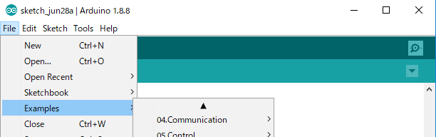
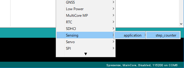
On the Arduino IDE, select File→ Examples → Sensing under "Examples for Spresense" → application → step_counter and open the example sketch.
Compile this sketch and upload it to the Spresense board.
When you open serial monitor, the pedometer and other information will be displayed in real time.
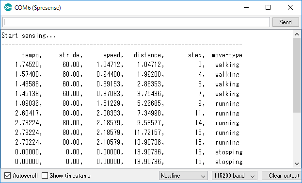
- tempo
-
Number of steps per second [Hz]
- stride
-
Stride [cm]
This is fixed value. - speed
-
Moving speed [m/s]
- distance
-
Moving distance [m]
The option of calculating the distance by fusing GPS positioning data will be supported in the future.
The current released software does not use GPS data. - step
-
Number of steps
- move-type
-
Activity recognition result (stopping, walking and running)
2.1.2. Try to change the physical sensor of Step Counter
Here, let’s change the physical sensor to another sensor.
-
Sensor board to ROHM’s SPRESENSE-SENSOR-EVK-701.
-
-
How to install KX122 Arduino library
-
Select
Clone or download → Download ZIPon GitHub site and download a ZIP file. -
Extract the downloaded ZIP file into any folder.
-
On Arduino IDE menu, open
Sketch → Include Library → Add .ZIP Library…and select theKX122folder from the extracted folder. -
If
Library added to your libraries.is shown on Arduino IDE, the installation is successful.
-
-
How to change step_counter.ino is below.
-
Include library
Change to inclue <KX122.h>.
#include <BMI160Gen.h>to
#include <Wire.h> #include <KX122.h> KX122 kx122(KX122_DEVICE_ADDRESS_1F); -
setup() function
Change to initialize KX122. The
accel_rateis set to 50 Hz by default of KX122 library./* Initialize device. */ BMI160.begin(BMI160GenClass::I2C_MODE, i2c_addr); /* Set device setting */ BMI160.setAccelerometerRange(accel_range); BMI160.setAccelerometerRate(accel_rate);to
Wire.begin(); kx122.init(); -
loop() function
Change to get the acceleration data from KX122.
  float x;
  float y;
  float z;

  /* Read raw accelerometer measurements from BMI160 */

  BMI160.readAccelerometerScaled(x, y, z);

  AccelSensor.write_data(x, y, z);
to
  float acc[3];

  /* Read raw accelerometer measurements from KX122 */

  kx122.get_val(acc);

  AccelSensor.write_data(acc[0], acc[1], acc[2]);
After applying the above modifications, you should be able to work the Step Counter with KX122.
2.1.3. Let’s try to create the unique logical sensor of Step Counter
If you want to implement your own Step Counter algorithm instead of Sony’s provided Step Counter algorithm, create a logic sensor client as follow.
Create a logical sensor class that inherits SensorClient .
For example, implement MyCounterClass in MyCounter.h. Include the header file as needed. For example, SensorClient.h is required, but sensing/logical_sensor/step_counter.h is necessary only if you want to use the StepCounter definition.
Also, as an example, the figure below shows the storage location of generally used code.
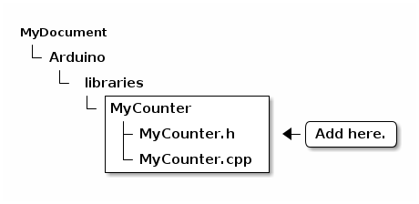
MyCounter code storage locationAbove diagram is an example of Windows environment.
The Arduino directory is ~/Arduino in Ubuntu environment and ~/Documents/Arduino in macOS environment.
class MyCounterClass : public SensorClientOverride the following methods of MyCounterClass on MyCounter.cpp .
bool begin(int id,
           uint32_t subscriptions,
           int      rate,
           int      sample_watermark_num,
           int      size_per_sample));

int publish(FAR void* data,
            uint32_t  size_per_sample,
            uint32_t  freq,
            uint32_t  sample_watermark_num,
            uint32_t  timestamp);

int subscribe(sensor_command_data_mh_t& data);-
Implementation of
begin():
Set initial settings for MyCounter. It is necessary to register a callback function to receive published accelerometer data. The callback function calls MyCounter’s subscribe() and get the data.
/* Callback function to receive accel sensor data. */

unsigned char mycounter_cb(sensor_command_data_mh_t &data)
{
  /* MyCounter subscribes to the received accel data. */

  return MyCounter.subscribe(data);
}

/* Initial setting of MyCounterClass. */

bool MyCounterClass::begin(int      id,
                           uint32_t subscriptions,
                           int      rate,
                           int      sample_watermark_num,
                           int      size_per_sample)
{
  /* Call super class begin() method. */

  return SensorClient::begin(id,
                             subscriptions,
                             rate,
                             sample_watermark_num,
                             size_per_sample,
                             mycounter_cb);        /* <-- Register callback function. */
}-
Implementation of
subscribe():
You can create your own Step Counter by subscribing to the accelerometer data and processing it with your own algorithm.
If you use AccelSensorClass which is provided by the library, the data which is publised from accel sensor is 50 samples of acceleration data. The acceleration data is sampled by 50Hz. And the structure of them is data array of x, y, z axis acceleration (the unit is [G]). This structure is defined as st_accel_axis. Call Subscribe() in the base class ( SensorClient ) to get this data.
Next, please apply your original process and publish result of them. In this example, you will publish with SensorResultStepCounter data format. Each parameter of the data format is described here for more details.
/* Subscribe the accel sensor data which is published from AccelSenseorClass. */

int MyCounterClass::subscribe(sensor_command_data_mh_t& data)
{
  struct st_accel_axis
  {
    float x;
    float y;
    float z;
  } *accel_axis;

  /* Get accel sensor data via subscribe() of super class. */

  accel_axis = static_cast<accel_axis*>(SensorClient::subscribe(data));
  uint32_t  timestamp = data.time;

  /* In this sample, output parameter structure is SensorResultStepCounter. */

  SensorResultStepCounter output;

  /*
    Implement your own algorithm and put a value in output.
   */

  /* Publish processed data to subscriber. */

  publish(&output,
          sizeof(SensorResultStepCounter),
          1, /* 1Hz */
          1, /* 1sample */
          timestamp);
}
The subscribed data is sensor_command_data_mh_t . Please refer to here for this data structure.
|
-
Implementation of
publish():
publish() send the data calculated by MyCounter.
The StepCounterReader is provided as a sample of the reading application client, and if you use it as it is, the data structure to publish is
SensorResultStepCounterNote that the parameter exec_result in SensorResultStepCounter should be set to SensorOK to notify result to application.
As mentioned above, when passed in the form of SensorResultStepCounter , publish() of the base class ( SensorClient ) can be used as it is.
SensorResultStepCounter format is below.
/*--------------------------------------------------------------------------*/
/**
 * @struct StepCounterStepInfo
 * @brief the structure of STEP_COUNTER results.
 */
typedef struct {

  float    tempo;     /**< Indicates tempo of walking / jogging calculated
                       *   from the input acceleration data.
                       *   The unit is [Hz].
                       */
  float    stride;    /**< Indicates stride calculated
                       *   from input acceleration data.
                       *   The unit is [cm].
                       */
  float    speed;     /**< Indicates speed of walking / jogging calculated
                       *   from the input acceleration data.
                       *   The unit is [m/s].
                       */
  float    distance;  /**< Indicates cumulative travel distance calculated
                       *   from the input acceleration data.
                       *   The unit is [m].
                       */
  uint32_t step;      /**< Indicates the number of steps calculated
                       *   from the input acceleration data.
                       * The unit is [step].
                       */
  StepCounterMovementType  movement_type; /**<
                                    * Indicates the walking type calculated
                                    * from the input acceleration data.
                                    */
  uint64_t          time_stamp;    /**< Indicates latest timestamp of the
                                    *   acceleration sensor data used.
                                    */
} StepCounterStepInfo;

/*--------------------------------------------------------------------------*/
/**
 * @struct SensorResultStepCounter
 * @brief the structure of sensor result on step counter commands.
 */
typedef struct
{
  SensorExecResult exec_result; /**< Execute resule.  */

  union
    {
      StepCounterStepInfo steps;        /**< Step count.         */
      SensorAssertionInfo assert_info;  /**< Assert information. */
    };
} SensorResultStepCounter;
2.1.4. Let’s try to change the data according to your logic sensor
Of course, you may want to change the resulting sensor data to match your own logic sensor.
In that case, use your defined data type (e.g. MyStepCounterResult) in publish() of MyCounter class.
int MyCounterClass::subscribe(sensor_command_data_mh_t& data)
{
  ..(Omission)..

  MyStepCounterResult output;

  publish(&output,
          sizeof(MyStepCounterResult),
          1, /* 1Hz */
          1, /* 1sample */
          timestamp);
}
Please implement as follows in Application ( StepCountReaderClass ).
subscribe()
{
  MyStepCounterResult* steps = reinterpret_cast<MyStepCounterResult*>(ApplicationSensorClass.subscribe(data));
}3. LTE tutorial
The LTE tutorials explain how to run the various sample sketches.
3.1. Get modem information
3.1.1. Overview
This sample sketch retrieves information about the modem. The sketch will obtain the following information after the modem is turned on:
-
IMEI
-
Firmware Version
3.1.2. Requirements
-
Spresense Main Board
-
Spresense LTE extension board
For instructions on how to connect the boards, please refer to How to connect the Spresense main board to the Spresense LTE extension board.
3.1.3. Instructions
-
From the Arduino IDE, select
File → Examples → LTE → LteTestModemto open the example sketch.
-
In
Tools → Portselect the COM port of Spresense and upload the sketch. -
After compiling and uploading are finished, start the serial monitor.
-
Make sure the baud rate is set to 115200 bps and you should see the message below.


3.1.4. Application Description
The application consists of three different parts: initialization, setup() and loop().
3.1.4.1. initialization
-
Include the header file for the library used in this sketch.
// libraries
#include <LTE.h>  (1)
1 Include the <LTE.h> header file to use the LTE library to register the modem to the LTE network. -
Instantiate the class to be used.
// initialize the library instance
LTEModem modem;  (1)
1 Initializes an instance of the LTEModem class. -
Initialize the variables used in the sketch.
// IMEI variable
String IMEI = "";     (1)
String VERSION = "";
LTENetworkRatType RAT = LTE_NET_RAT_UNKNOWN;
1 Define the variables used to store the IMEI number, firmware version and RAT(Radio Access Technology) obtained from the modem.
3.1.4.2. setup()
-
The setup() function sets up the Serial and modem classes.
void setup() {
  // initialize serial communications and wait for port to open:
  Serial.begin(115200);                          (1)
  while (!Serial) {
      ; /* wait for serial port to connect. Needed for native USB port only */
  }

  // start modem test (reset and check response)
  Serial.println("Starting modem test...");
  if (LTE_IDLE == modem.begin()) {               (2)
    Serial.println("modem.begin() succeeded.");
  } else {
    Serial.println("ERROR, no modem answer.");
  }
}
1 Setup Serial for displaying messages. 2 Call the begin() method of LTEModem.
Calling the begin() method will turn on the modem. When the modem is successfully turned on, the begin() method returns LTE_IDLE.
3.1.4.3. loop()
-
The loop() function retrieves the IMEI number, firmware version and RAT of the modem and displays them in the serial monitor.
void loop() {

  // IMEI of the modem
  IMEI = modem.getIMEI();                 (1)
  Serial.println("IMEI: " + IMEI);

  //Firmware version of the modem.
  VERSION = modem.getFirmwareVersion();   (2)
  Serial.println("VERSION: " + VERSION);

  // Current RAT of the modem.
  RAT = modem.getRAT();                   (3)

  switch (RAT) {
    case LTE_NET_RAT_CATM:
      Serial.println("RAT: LTE-M (LTE Cat-M1)");
      break;
    case LTE_NET_RAT_NBIOT:
      Serial.println("RAT: NB-IoT");
      break;
    default:
      Serial.println("RAT: Unknown type [" + String(RAT) + "]");
      break;
  }

  sleep(1);
}
1 Get the IMEI number from the modem using the getIMEI() method of LTEModem. 2 Get the firmware version from the modem using the getFirmwareVersion() method of LTEModem. 3 Get the RAT set on the modem using the getRAT() method of LTEModem.
3.2. Get network status
3.2.1. Overview
This sample sketch retrieves the LTE network status.
The sketch registers the modem to the LTE network and then retrieves the following information:
-
IP Address
-
Signal strength
-
Network carrier name
3.2.2. Requirements
-
Spresense Main Board
-
Spresense LTE extension board
-
SIM card
For instructions on how to connect the boards, please refer to How to connect the Spresense main board to the Spresense LTE extension board.
This sketch requires a SIM card to connect to the network.
Please check the Confirmed LTE operator list.
3.2.3. Instructions
-
From the Arduino IDE, select
File → Examples → LTE → LteScanNetworksto open the example sketch.
-
Define the APN parameters required to register the modem to the LTE network.
You will need to modify the values to match your SIM.#define APP_LTE_APN "apn" // replace your APN (1) /* APN authentication settings * Ignore these parameters when setting LTE_NET_AUTHTYPE_NONE. */ #define APP_LTE_USER_NAME "user" // replace with your username (2) #define APP_LTE_PASSWORD "password" // replace with your password (3)1 Please enter the access point name that matches your SIM. 2 Enter a username that matches your SIM. 3 Enter a password that matches the SIM you are using. -
Set the RAT to use.
Switch the comment out part according to the SIM you are using./* RAT to use * Refer to the cellular carriers information * to find out which RAT your SIM supports. * The RAT set on the modem can be checked with LTEModemVerification::getRAT(). */ #define APP_LTE_RAT (LTE_NET_RAT_CATM) // RAT : LTE-M (LTE Cat-M1) (1) // #define APP_LTE_RAT (LTE_NET_RAT_NBIOT) // RAT : NB-IoT (2)1 Use this definition when communicating by LTE-M (LTE Cat-M1). 2 Use this definition when communicating by NB-IoT. -
In
Tools → Portselect the COM port of Spresense and upload the sketch -
After compiling and uploading are finished, start the serial monitor.
-
Make sure the baud rate is set to 115200 bps and you should see the message below.


|
Depending on the environment, network communication may become unstable and may not work properly. |
3.2.4. Application Description
The application consists of three different parts: initialization, setup() and loop().
3.2.4.1. initialization
-
Include the header file for the library used in this sketch.
// libraries #include <LTE.h> (1)1 Include the <LTE.h> header file to use the LTE library to register the modem to the LTE network. -
Define the APN parameters required to register the modem to the LTE network.
The values have to be replaced with the ones matching your SIM card.#define APP_LTE_APN "apn" // replace your APN (1) /* APN authentication settings * Ignore these parameters when setting LTE_NET_AUTHTYPE_NONE. */ #define APP_LTE_USER_NAME "user" // replace with your username (2) #define APP_LTE_PASSWORD "password" // replace with your password (3)1 Please enter the access point name that matches your SIM. 2 Enter a username that matches your SIM. 3 Enter a password that matches the SIM you are using. -
Instantiate the classes to be used.
// initialize the library instance LTE lteAccess; (1) LTEScanner scannerNetworks; (2)1 Initializes an instance of the LTE class. 2 Initializes an instance of the LTEScanner class.
3.2.4.2. setup()
-
The setup() function sets up the Serial and modem classes.
void setup() { // initialize serial communications and wait for port to open: Serial.begin(115200); (1) while (!Serial) { ; // wait for serial port to connect. Needed for Leonardo only } Serial.println("LTE networks scanner"); while (true) { /* Power on the modem and Enable the radio function. */ if (lteAccess.begin() != LTE_SEARCHING) { (2) Serial.println("Could not transition to LTE_SEARCHING."); Serial.println("Please check the status of the LTE board."); for (;;) { sleep(1); } } /* The connection process to the APN will start. * If the synchronous parameter is false, * the return value will be returned when the connection process is started. */ if (lteAccess.attach(APP_LTE_RAT, APP_LTE_APN, APP_LTE_USER_NAME, APP_LTE_PASSWORD, APP_LTE_AUTH_TYPE, APP_LTE_IP_TYPE) == LTE_READY) { (3) Serial.println("attach succeeded."); break; } /* If the following logs occur frequently, one of the following might be a cause: * - APN settings are incorrect * - SIM is not inserted correctly * - If you have specified LTE_NET_RAT_NBIOT for APP_LTE_RAT, * your LTE board may not support it. * - Rejected from LTE network */ Serial.println("An error has occurred. Shutdown and retry the network attach process after 1 second."); lteAccess.shutdown(); (4) sleep(1); } }1 Setup Serial for displaying messages. 2 Call the begin() method of the LTE class. Calling the begin() method will turn on the modem and search the network.
When the network search is successfully started, the begin() method returns LTE_SEARCHING.3 Call the attach() method of LTE.
Register the modem with the LTE network by calling the attach() method.
When the modem is successfully registered to the LTE network, the attach() method returns LTE_READY.4 If the method does not return the expected return value, the LTE method shutdown() will be called.
This will turn off the modem.
3.2.4.3. loop()
-
The loop() function obtains the IP address, the name of the connected LTE network carrier and the signal strength of the LTE network, and displays them in the serial monitor.
void loop() { // Assigned IP address IPAddress address = lteAccess.getIPAddress(); (1) Serial.print("IP address: "); Serial.println(address); // currently connected carrier Serial.print("Current carrier: "); Serial.println(scannerNetworks.getCurrentCarrier()); (2) // return signal strength Serial.print("Signal Strength: "); Serial.print(scannerNetworks.getSignalStrength()); (3) Serial.println(" [dBm]"); sleep(1); }1 Get the IP address assigned by the LTE network with the getIPAddress() method of LTE. 2 Get the name of the connected LTE network carrier with the LTEScanner’s getCurrentCarrier() method. 3 The getSignalStrength() method of the LTEScanner retrieves the signal strength of the LTE network.
3.3. Send a HTTP GET request to retrieve server data
3.3.1. Overview
This sample sketch requests data from a server via the LTE network. The sketch will register the modem to the LTE network, send a HTTP GET request to a server and retrieve the result.
3.3.2. Requirements
-
Spresense Main Board
-
Spresense LTE extension board
-
SIM card
For instructions on how to connect the boards, please refer to How to connect the Spresense main board to the Spresense LTE extension board.
This sketch requires a SIM card to connect to the network.
Please check the Confirmed LTE operator list.
3.3.3. Instructions
-
From the Arduino IDE, select
File → Examples → LTE → LteWebClientto open the example sketch.
-
Define the APN parameters required to register the modem to the LTE network.
You will need to modify the values to match your SIM.#define APP_LTE_APN "apn" // replace your APN (1) /* APN authentication settings * Ignore these parameters when setting LTE_NET_AUTHTYPE_NONE. */ #define APP_LTE_USER_NAME "user" // replace with your username (2) #define APP_LTE_PASSWORD "password" // replace with your password (3)1 Please enter the access point name that matches your SIM. 2 Enter a username that matches your SIM. 3 Enter a password that matches the SIM you are using. -
Set the RAT to use.
Switch the comment out part according to the SIM you are using./* RAT to use * Refer to the cellular carriers information * to find out which RAT your SIM supports. * The RAT set on the modem can be checked with LTEModemVerification::getRAT(). */ #define APP_LTE_RAT (LTE_NET_RAT_CATM) // RAT : LTE-M (LTE Cat-M1) (1) // #define APP_LTE_RAT (LTE_NET_RAT_NBIOT) // RAT : NB-IoT (2)1 Use this definition when communicating by LTE-M (LTE Cat-M1). 2 Use this definition when communicating by NB-IoT. -
In
Tools → Portselect the COM port of Spresense and upload the sketch. -
After compiling and uploading are finished, start the serial monitor.
-
Make sure the baud rate is set to 115200 bps and you should see the message below.


|
Depending on the environment, network communication may become unstable and may not work properly. |
3.3.4. Application Description
The application consists of three different parts: initialization, setup() and loop().
3.3.4.1. initialization
-
Include the header file for the library used in this sketch.
// libraries #include <LTE.h> (1)1 Include the <LTE.h> header file to use the LTE library to register the modem to the LTE network. -
Define the APN parameters required to register the modem to the LTE network.
The values have to be replaced with the ones matching your SIM card.#define APP_LTE_APN "apn" // replace your APN (1) /* APN authentication settings * Ignore these parameters when setting LTE_NET_AUTHTYPE_NONE. */ #define APP_LTE_USER_NAME "user" // replace with your username (2) #define APP_LTE_PASSWORD "password" // replace with your password (3)1 Please enter the access point name that matches your SIM. 2 Enter a username that matches your SIM. 3 Enter a password that matches the SIM you are using. -
Instantiate the classes to be used.
// initialize the library instance LTE lteAccess; (1) LTEClient client; (2)1 Initializes an instance of the LTE class. 2 Initializes an instance of the LTEClient class. -
Defines the parameters of the server to connect to.
// URL, path & port (for example: arduino.cc) char server[] = "arduino.cc"; (1) char path[] = "/asciilogo.txt"; (2) int port = 80; // port 80 is the default for HTTP (3)1 URL of the server to connect to 2 Server path of the HTTP GET request 3 Port number of the server to connect to
3.3.4.2. setup()
-
The setup() function sets up the Serial and modem classes.
void setup() { // initialize serial communications and wait for port to open: Serial.begin(115200); (1) while (!Serial) { ; // wait for serial port to connect. Needed for native USB port only } Serial.println("Starting web client."); while (true) { /* Power on the modem and Enable the radio function. */ if (lteAccess.begin() != LTE_SEARCHING) { (2) Serial.println("Could not transition to LTE_SEARCHING."); Serial.println("Please check the status of the LTE board."); for (;;) { sleep(1); } } /* The connection process to the APN will start. * If the synchronous parameter is false, * the return value will be returned when the connection process is started. */ if (lteAccess.attach(APP_LTE_RAT, APP_LTE_APN, APP_LTE_USER_NAME, APP_LTE_PASSWORD, APP_LTE_AUTH_TYPE, APP_LTE_IP_TYPE) == LTE_READY) { (3) Serial.println("attach succeeded."); break; } /* If the following logs occur frequently, one of the following might be a cause: * - APN settings are incorrect * - SIM is not inserted correctly * - If you have specified LTE_NET_RAT_NBIOT for APP_LTE_RAT, * your LTE board may not support it. * - Rejected from LTE network */ Serial.println("An error has occurred. Shutdown and retry the network attach process after 1 second."); lteAccess.shutdown(); (4) sleep(1); } // if you get a connection, report back via serial: if (client.connect(server, port)) { (5) Serial.println("connected"); // Make a HTTP request: client.print("GET "); (6) client.print(path); client.println(" HTTP/1.1"); client.print("Host: "); client.println(server); client.println("Connection: close"); client.println(); } else { // if you didn't get a connection to the server: Serial.println("connection failed"); } }1 Setup Serial for displaying messages. 2 Call the begin() method of the LTE class. Calling the begin() method will turn on the modem and search the network.
When the network search is successfully started, the begin() method returns LTE_SEARCHING.3 Call the attach() method of LTE.
Register the modem with the LTE network by calling the attach() method.
When the modem is successfully registered to the LTE network, the attach() method returns LTE_READY.4 If the method does not return the expected return value, the LTE method shutdown() will be called.
This will turn off the modem.5 Call the connect() method of LTEClient.
Calling the connect() method connects to the host name and port specified in the arguments.
The connect() method returns the value 1 when the connection to the server is successfully established.6 Send an HTTP request to the server using the print() and println() methods of LTEClient.
3.3.4.3. loop()
-
The loop() function receives the HTTP response and displays the response message in the serial monitor.
void loop() { // if there are incoming bytes available // from the server, read them and print them: if (int len = client.available()) { (1) char buff[len + 1]; buff[len] = '\0'; client.read(buff, len); (2) Serial.print(buff); } // if the server's disconnected, stop the client: if (!client.available() && !client.connected()) { (3) Serial.println(); Serial.println("disconnecting."); client.stop(); (4) // do nothing forevermore: for (;;) sleep(1); } }1 Use the available() method of LTEClient to get the number of bytes available for reading. 2 Use the read() method of LTEClient to read the data received from the connected server into a buffer and output it in the serial monitor. 3 Use the connected() method of LTEClient to find out whether the client is connected to the server or not. 4 Disconnect from the server using the stop() method of LTEClient.
3.4. Checking HTTP Client behavior using the TLS protocol
3.4.1. Overview
This sample sketch demonstrates how to create a HTTP Client that uses the TLS protocol.
The sketch will register the modem to the LTE network, connect to a server using the TLS protocol and use the Arduino HTTP Client library to test the get() and post() methods that it provides.
|
If the LTE firmware version is RK_03_00_00_00_00_04121_001, the TLS communication API may not work. (Please refer to here ) |
3.4.2. Environment
-
Spresense Main Board
-
Spresense LTE extension board
-
SIM card
-
microSD card
For the instructions on how to connect the hardware, please refer to How to connect the Spresense main board to the Spresense LTE extension board.
This sketch requires a SIM card to connect to the network.
Please check the Confirmed LTE operator list.
3.4.3. Instructions
-
From the Arduino IDE, select
File → Example sketch → Example sketch for Spresense LTE → LteHttpSecureClientto open the example sketch.
-
From the Arduino IDE, select
Tools → Manage Libraries….
TypeArduinoHttpClientin the search field and install theArduinoHttpClient by Arduinoitem in the results.
-
Define the APN parameters associated with your SIM card to register the modem to the LTE network.
#define APP_LTE_APN "apn" // replace your APN                       (1)

/* APN authentication settings
 * Ignore these parameters when setting LTE_NET_AUTHTYPE_NONE.
 */
#define APP_LTE_USER_NAME "user"     // replace with your username  (2)
#define APP_LTE_PASSWORD  "password" // replace with your password  (3)
1 Please enter the access point name that matches your SIM. 2 Enter a user name that matches your SIM. 3 Enter a password that matches the SIM you are using. -
Set the RAT to use.
Switch the comment out part according to the SIM you are using./* RAT to use * Refer to the cellular carriers information * to find out which RAT your SIM supports. * The RAT set on the modem can be checked with LTEModemVerification::getRAT(). */ #define APP_LTE_RAT (LTE_NET_RAT_CATM) // RAT : LTE-M (LTE Cat-M1) (1) // #define APP_LTE_RAT (LTE_NET_RAT_NBIOT) // RAT : NB-IoT (2)1 Use this definition when communicating by LTE-M (LTE Cat-M1). 2 Use this definition when communicating by NB-IoT. -
Export the root certificate required for the TLS protocol.
Please refer to root certificate export procedure for the procedure. -
Put the certificate on the microSD card. Make sure that the name of the directory where it is located matches the illustration below:
microSD: └CERTS/ └httpbin-org.pem -
Modify
ROOTCA_FILEin the sample sketch to match the name of the file on the microSD card.#define ROOTCA_FILE "CERTS/httpbin-org.pem" // Define the path to a file containing CA // certificates that are trusted.Set the file name of the root certificate saved on the microSD card.
-
Select the COM port of Spresense in Tools → Serial Port and perform the write operation.
-
After compiling and writing (Upload) is finished, start the serial monitor.
-
If you select the baud rate 115200 bps you should see log output as shown below.


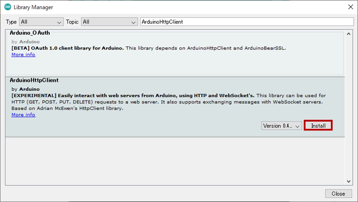

|
If the terminal log does not proceed beyond the indication |
|
Depending on the operating environment, the communication state may become unstable and may not working correctly. |
3.4.4. Program Description
The application consists of three different steps: "initialization", "setup()", and "loop()". These steps are explained in detail below.
3.4.4.1. initialization
-
Include header files for the libraries used in this sketch.
// libraries
#include <ArduinoHttpClient.h> (1)
#include <RTC.h>               (2)
#include <SDHCI.h>             (3)
#include <LTE.h>               (4)
1 To use the Arduino HTTP Client library for sending HTTP GET and POST requests, include <ArduinoHttpClient.h>. 2 Include the header file <RTC.h> to use the RTC library to set the SPRESENSE time. 3 Include the header file <SDHCI.h> to use the SD library to reference the certificate and private key required for the TLS protocol. 4 Include the header file <LTE.h> to use the LTE library to register the modem to the LTE network. -
Define the APN parameters required to register the modem to the LTE network.
The values must be updated to match those of your SIM card.#define APP_LTE_APN "apn" // replace your APN (1) /* APN authentication settings * Ignore these parameters when setting LTE_NET_AUTHTYPE_NONE. */ #define APP_LTE_USER_NAME "user" // replace with your username (2) #define APP_LTE_PASSWORD "password" // replace with your password (3)1 Please enter the access point name that matches your SIM. 2 Enter a user name that matches your SIM. 3 Enter a password that matches your SIM. -
Define the parameters of the server you are connecting to.
// URL, path & port (for example: httpbin.org)
char server[] = "httpbin.org";                       (1)
char getPath[] = "/get";                             (2)
char postPath[] = "/post";                           (3)
int port = 443; // port 443 is the default for HTTPS (4)
1 URL of the server to connect to 2 Server path of the HTTP GET destination 3 Server path of the HTTP POST destination 4 Port number of the server to connect to -
Define the parameters for the root certificate, client certificate, and private key required for the TLS protocol.
The file names must be updated to match those of the files saved in the microSD card.#define ROOTCA_FILE "path/to/cafile" // Define the path to a file containing CA (1) // certificates that are trusted. #define CERT_FILE "path/to/certfile" // Define the path to a file containing certificate (2) // for this client, if required by the server. #define KEY_FILE "path/to/keyfile" // Define the path to a file containing private key (3) // for this client, if required by the server.1 Describe the file name of the root certificate stored on the microSD card. 2 Describe the file name of the client certificate stored on the microSD card. 3 Describe the file name of the private key stored on the microSD card. -
Initialize the instance of the class to be used.
// initialize the library instance LTE lteAccess; LTETLSClient tlsClient; HttpClient client = HttpClient(tlsClient, server, port); (1) SDClass theSD;1 Specifies an instance of LTETLSClient when initializing an instance of HttpClient.
3.4.4.2. setup()
This section describes the setup() function step by step.
-
Setup Serial for displaying log messages.
// initialize serial communications and wait for port to open: Serial.begin(115200); while (!Serial) { ; // wait for serial port to connect. Needed for native USB port only } Serial.println("Starting secure HTTP client."); -
Mount the microSD card in theSD.begin() method.
/* Initialize SD */ while (!theSD.begin()) { ; /* wait until SD card is mounted. */ } -
Register the modem to the LTE network.
while (true) { /* Power on the modem and Enable the radio function. */ if (lteAccess.begin() != LTE_SEARCHING) { (1) Serial.println("Could not transition to LTE_SEARCHING."); Serial.println("Please check the status of the LTE board."); for (;;) { sleep(1); } } /* The connection process to the APN will start. * If the synchronous parameter is false, * the return value will be returned when the connection process is started. */ if (lteAccess.attach(APP_LTE_RAT, APP_LTE_APN, APP_LTE_USER_NAME, APP_LTE_PASSWORD, APP_LTE_AUTH_TYPE, APP_LTE_IP_TYPE) == LTE_READY) { (2) Serial.println("attach succeeded."); break; } /* If the following logs occur frequently, one of the following might be a cause: * - APN settings are incorrect * - SIM is not inserted correctly * - If you have specified LTE_NET_RAT_NBIOT for APP_LTE_RAT, * your LTE board may not support it. * - Rejected from LTE network */ Serial.println("An error has occurred. Shutdown and retry the network attach process after 1 second."); lteAccess.shutdown(); (3) sleep(1); }1 Use the lteAccess.begin() method to start exploring the LTE network. lteAccess.begin() method is called repeatedly until it starts exploring the LTE network. 2 Use the lteAccess.attach() method to register the modem with the LTE network. The loop is exited when the modem is successfully registered with the LTE network. 3 If the modem fails to register with the LTE network, use the lteAccess.shutdown() method to turn off the modem, call sleep() to halt execution for about one second and then retry the LTE network search process. If your SIM has a PIN lock, please provide the PIN unlock code in the begin() method.
-
Set the SPRESENSE time and output the set time to serial.
void printClock(RtcTime &rtc) (1) { printf("%04d/%02d/%02d %02d:%02d:%02d\n", rtc.year(), rtc.month(), rtc.day(), rtc.hour(), rtc.minute(), rtc.second()); } void setup() { : // Set local time (not UTC) obtained from the network to RTC. RTC.begin(); unsigned long currentTime; while(0 == (currentTime = lteAccess.getTime())) { (2) sleep(1); } RtcTime rtc(currentTime); (3) printClock(rtc); (4) RTC.setTime(rtc); (5) }1 Define the printClock() function to output the time given in the parameter to serial. 2 Use the lteAccess.getTime() method to get the local time (in seconds from the source). 3 Create an instance of RtcTime with the local time. 4 Outputs the local time to serial using the printClock() function. 5 Use the RTC.setTime() method to set the local time of SPRESENSE.
3.4.4.3. loop()
This section describes the loop function.
-
Configure the modem with the certificate and private key stored on the microSD card.
// Set certifications via a file on the SD card before connecting to the server File rootCertsFile = theSD.open(ROOTCA_FILE, FILE_READ); (1) tlsClient.setCACert(rootCertsFile, rootCertsFile.available()); (2) rootCertsFile.close(); // Remove these commented out if client authentication is required. //File certsFile = theSD.open(CERT_FILE, FILE_READ); //tlsClient.setCertificate(certsFile, certsFile.available()); (3) //certsFile.close(); //File priKeyFile = theSD.open(KEY_FILE, FILE_READ); //tlsClient.setPrivateKey(priKeyFile, priKeyFile.available()); (4) //priKeyFile.close();1 Use theSD.open() method to create a File instance of the root certificate. 2 Set the root certificate to the modem by providing the File instance to the tlsClient.setCACert() method. 3 If a client certificate is required, create a File instance just like the one for the root certificate and use tlsClient.setCertificate() to set it in the modem. 4 If a private key is required, create a File instance for this one as well and use tlsClient.setPrivateKey() to set it in the modem. -
Verify the operation of the HTTP GET method.
// HTTP GET method Serial.println("making GET request"); client.get(getPath); (1) // read the status code and body of the response int statusCode = client.responseStatusCode(); (2) String response = client.responseBody(); (3) Serial.print("Status code: "); Serial.println(statusCode); (4) Serial.print("Response: "); Serial.println(response); (5) Serial.println("Wait five seconds"); sleep(5);1 Uses client.get() to connect to the server using the TLS protocol and send the HTTP GET request. 2 Uses client.responseStatusCode() to receive a response message from the server and extract the status code from it. 3 Uses client.responseBody() to get the body of the server’s response message. 4 Outputs the obtained status code to serial. 5 Outputs the body of the retrieved message to serial. -
Check the operation of the HTTP POST method.
// HTTP POST method Serial.println("making POST request"); String contentType = "application/x-www-form-urlencoded"; (1) String postData = "name=Alice&age=12"; (2) client.post(postPath, contentType, postData); (3) // read the status code and body of the response statusCode = client.responseStatusCode(); (4) response = client.responseBody(); (5) Serial.print("Status code: "); Serial.println(statusCode); (6) Serial.print("Response: "); Serial.println(response); (7) // do nothing forevermore: for (;;) sleep(1);1 Specifies the Content-Type of the message to be POSTed. 2 Specifies the body part of the message to be POSTed. 3 Uses client.post() to connect to the server using the TLS protocol and send the HTTP POST request. 4 Uses client.responseStatusCode() to receive the response message from the server and extract the status code from it. 5 Uses client.responseBody() to get the body of the server’s response message. 6 Outputs the obtained status code to serial. 7 Outputs the body of the retrieved message to serial.
3.5. Verifying the NTP Client using the UDP protocol.
3.5.1. Overview
This sample sketch shows how to run the NTP Client using the UDP protocol.
The sketch registers the modem to the LTE network, connects to a NTP server using the UDP protocol and calls the update() method provided by the Arduino NTP Client library.
3.5.2. Requirements
-
Spresense Main Board
-
Spresense LTE extension board
-
SIM card
For instructions on how to connect the boards, please refer to How to connect the Spresense main board to the Spresense LTE extension board.
This sketch requires a SIM card to connect to the network.
Please check the Confirmed LTE operator list.
3.5.3. Instructions
-
From the Arduino IDE, select
File → Examples → LTE → LteNtpClientto open the example sketch.
-
From the Arduino IDE, select
Tools → Manage Libraries….
TypeNTPClientin the search field and installNTPClient by Fabrice Weinbergin the results.
-
Define the APN parameters required to register the modem to the LTE network.
You will need to modify the values to match your SIM.#define APP_LTE_APN "apn" // replace your APN (1) /* APN authentication settings * Ignore these parameters when setting LTE_NET_AUTHTYPE_NONE. */ #define APP_LTE_USER_NAME "user" // replace with your username (2) #define APP_LTE_PASSWORD "password" // replace with your password (3)1 Please enter the access point name that matches your SIM. 2 Enter a username that matches your SIM. 3 Enter a password that matches the SIM you are using. -
Set the RAT to use.
Switch the comment out part according to the SIM you are using./* RAT to use * Refer to the cellular carriers information * to find out which RAT your SIM supports. * The RAT set on the modem can be checked with LTEModemVerification::getRAT(). */ #define APP_LTE_RAT (LTE_NET_RAT_CATM) // RAT : LTE-M (LTE Cat-M1) (1) // #define APP_LTE_RAT (LTE_NET_RAT_NBIOT) // RAT : NB-IoT (2)1 Use this definition when communicating by LTE-M (LTE Cat-M1). 2 Use this definition when communicating by NB-IoT. -
In
Tools → Portselect the COM port of Spresense and perform the write operation. -
After compiling and writing (
Upload) is finished, start the serial monitor. -
Make sure the baud rate is set to 115200 bps and you should see the message below.


|
Depending on the environment, network communication may become unstable and may not work properly. |
3.5.4. Application Description
The application consists of three different parts: initialization, setup() and loop().
3.5.4.1. initialization
-
Include header files for the libraries used in this sketch.
// libraries #include <NTPClient.h> (1) #include <LTE.h> (2)1 Include the <NTPClient.h> header file to use the Arduino NTP Client library to synchronize with the NTP server. 2 Include the <LTE.h> header file to use the LTE library to register the modem to the LTE network. -
Define the APN parameters required to register the modem to the LTE network.
The values have to be replaced with the ones matching your SIM card.// APN data #define LTE_APN "apn" // replace your APN (1) #define LTE_USER_NAME "user" // replace with your username (2) #define LTE_PASSWORD "password" // replace with your password (3)1 Please enter the access point name that matches your SIM. 2 Enter a username that matches your SIM. 3 Enter a password that matches the SIM you are using. -
Define the NTP server name, time offset and time synchronization interval.
#define NTP_SERVER_NAME "pool.ntp.org" (1) #define TIME_OFFSET (9 * 60 * 60) // time offset in seconds(This example is JST) (2) #define UPDATE_INTERVAL 60000 // update interval in milliseconds (3)1 Hostname of NTP server to synchronize 2 Time offset value 3 Time synchronization interval with NTP server -
Instantiate the classes to be used.
// initialize the library instance LTE lteAccess; (1) LTEUDP ntpUDP; (2) // You can specify the time server pool and the offset (in seconds, can be // changed later with setTimeOffset() ). Additionally you can specify the // update interval (in milliseconds, can be changed using setUpdateInterval() ). NTPClient timeClient(ntpUDP, NTP_SERVER_NAME, TIME_OFFSET, UPDATE_INTERVAL); (3)1 Initializes an instance of the LTE class. 2 Initializes an instance of the LTEUDP class. 3 Initializes an instance of the NTPClient class.
3.5.4.2. setup()
-
The setup() function sets up the Serial and modem classes, and starts the UDP client.
void setup() { // initialize serial communications and wait for port to open: Serial.begin(115200); (1) while (!Serial) { ; // wait for serial port to connect. Needed for native USB port only } Serial.println("Starting NTP client."); while (true) { /* Power on the modem and Enable the radio function. */ if (lteAccess.begin() != LTE_SEARCHING) { (2) Serial.println("Could not transition to LTE_SEARCHING."); Serial.println("Please check the status of the LTE board."); for (;;) { sleep(1); } } /* The connection process to the APN will start. * If the synchronous parameter is false, * the return value will be returned when the connection process is started. */ if (lteAccess.attach(APP_LTE_RAT, APP_LTE_APN, APP_LTE_USER_NAME, APP_LTE_PASSWORD, APP_LTE_AUTH_TYPE, APP_LTE_IP_TYPE) == LTE_READY) { (3) Serial.println("attach succeeded."); break; } /* If the following logs occur frequently, one of the following might be a cause: * - APN settings are incorrect * - SIM is not inserted correctly * - If you have specified LTE_NET_RAT_NBIOT for APP_LTE_RAT, * your LTE board may not support it. * - Rejected from LTE network */ Serial.println("An error has occurred. Shutdown and retry the network attach process after 1 second."); lteAccess.shutdown(); (4) sleep(1); } timeClient.begin(); (5) }1 Setup Serial for message display. 2 Call the begin() method of the LTE class. Calling the begin() method will turn on the modem and search the network.
When the network search is successfully started, the begin() method returns LTE_SEARCHING.3 Call the attach() method of LTE.
Register the modem with the LTE network by calling the attach() method.
When the modem is successfully registered to the LTE network, the attach() method returns LTE_READY.4 If the method does not return the expected return value, the LTE method shutdown() will be called.
This will turn off the modem.5 Use the begin() method of NTPClient to connect to the NTP server using the UDP protocol.
3.5.4.3. loop()
-
The loop() function updates the synchronization with the NTP server and displays the synchronization time in the serial output.
void loop() { timeClient.update(); (1) Serial.println(timeClient.getFormattedTime()); sleep(1); }1 Use the NTPClient update() method to synchronize the time with the NTP server at the update interval of UPDATE_INTERVAL.
3.6. Publish GNSS positioning information to AWS server
3.6.1. Overview
This sample sketch uses the GNSS Library to publish acquired positioning data to the MQTT broker using the MQTT protocol.
The sketch will register the modem to the LTE network and then connect to the MQTT broker using Arduino MQTT Client library. It starts positioning using the GNSS library and publishes a message containing the location and time to the MQTT broker using the Arduino MQTT Client library.
|
If the LTE firmware version is RK_03_00_00_00_00_04121_001, the TLS communication API may not work. (Please refer to here ) |
3.6.2. Environment requirements
-
Spresense main board
-
Spresense LTE extension board
-
SIM card
-
microSD card
For instructions on how to connect the boards, please refer to How to connect the Spresense main board to the Spresense LTE extension board.
This sketch requires a SIM card to be able to connect to the network.
Please check the Confirmed LTE operator list.
3.6.3. Procedure
-
To use AWS IoT you first need to create an AWS account.
-
For getting started with AWS IoT, please refer to Getting started with AWS IoT Core.
-
Download the certificate to your PC.
Download the certificate issued by following the guide describing how to create a thing object. The three files to download are as follows-
Root certificate:Amazon_Root_CA_1.pem
-
Client certificate:c3c4ff2375.cert.pem
-
Private key:c3c4ff2375.private.key
These file names are just examples. The actual names of the downloaded files may vary depending on your environment, so please change them accordingly.
-
-
Download the certificate to your PC and save it to a microSD card.
Create a directory named CERTS on the microSD card and put the three files in it. -
From the Arduino IDE, select
File → Example Sketch → Example Sketch for Spresense LTE → LteGnssTrackerto open the example sketch.
-
From the Arduino IDE, select
Tools → Manage Libraries….
TypeArduinoMqttClientin the search field of the dialog and installArduinoMqttClient by Arduinofrom the list of results.
-
Define the APN parameters required to register the modem to the LTE network.
You will have to modify these values to match your SIM card.#define APP_LTE_APN "apn" // replace your APN (1) /* APN authentication settings * Ignore these parameters when setting LTE_NET_AUTHTYPE_NONE. */ #define APP_LTE_USER_NAME "user" // replace with your username (2) #define APP_LTE_PASSWORD "password" // replace with your password (3)1 Please enter the access point name that matches the SIM you are using. 2 Enter the user name that matches the SIM you are using. 3 Enter the password that matches the SIM you are using. -
Set the RAT to use.
Switch the comment out part according to the SIM you are using./* RAT to use * Refer to the cellular carriers information * to find out which RAT your SIM supports. * The RAT set on the modem can be checked with LTEModemVerification::getRAT(). */ #define APP_LTE_RAT (LTE_NET_RAT_CATM) // RAT : LTE-M (LTE Cat-M1) (1) // #define APP_LTE_RAT (LTE_NET_RAT_NBIOT) // RAT : NB-IoT (2)1 Use this definition when communicating by LTE-M (LTE Cat-M1). 2 Use this definition when communicating by NB-IoT. -
Describes the configuration parameters required to connect to the MQTT broker.
The procedure for checking the MQTT broker name is as follows:
-
Open the AWS IoT console.
-
Select Manage and then Things. Select the IoT thing you previously created and select Interact. The endpoint will appear in the HTTPS section of the thing’s details page.
// MQTT broker #define BROKER_NAME "your-MQTT-broker" // replace with your broker (1) #define BROKER_PORT 8883 // port 8883 is the default for MQTT over TLS. (2)1 Describe the endpoint displayed in the [HTTPS] section. 2 Specify the port to connect to. The default is 8883 and you can leave it unchanged in this procedure.
-
-
Describe the parameters of the root certificate, client certificate, and private key required for the TLS protocol.
Make sure the file names match those of the files saved on the microSD card.#define ROOTCA_FILE "CERTS/Amazon_Root_CA_1.pem" // Define the path to a file containing CA (1) // certificates that are trusted. #define CERT_FILE "CERTS/c3c4ff2375.cert.pem" // Define the path to a file containing certificate (2) // for this client, if required by the server. #define KEY_FILE "CERTS/c3c4ff2375.private.key" // Define the path to a file containing private key (3) // for this client, if required by the server.1 Describe the file name of the root certificate saved in the microSD card. 2 Describe the file name of the client certificate saved in the microSD card. 3 Describe the file name of the private key stored in the microSD card. The file names used above are just examples. Please replace with the names of the files you actually downloaded.
-
Describe the topic that the sample application will publish.
Checking the MQTT messages for a device in the AWS IoT MQTT client.// MQTT topic #define MQTT_TOPIC "spresense/gnss_tracker" // replace with your topic -
Select the COM port used by Spresense in Tools → Serial Port and perform the write operation.
-
After compiling and flashing the sketch, start the serial monitor.
-
Set baud rate to 115200 bps.
When the modem successfully registers with the LTE network and completes the connection to the MQTT broker, the messageYou’re connected to the MQTT broker!will be displayed.
After that, when positioning is completed,Position is fixed.will be displayed.
After the positioning is completed, the device will publish the positioning data every second for a total of 60 times. If successful, a message will be displayed as shown below.
If the terminal log does not proceed beyond the indication
Attempting to connect to the MQTT broker:, your Spresense LTE extension board firmware may be out of date.
Please update the Spresense LTE board firmware to refer Updater Tool .Depending on the operating environment, the communication may become unstable and not working correctly.
For more details, please the FAQ. -
Check the AWS IoT console to see if the message has been published.
-
Export the messages subscribed to in the AWS IoT console as a CSV file.
-
The downloaded CSV file will be processed to create GPS logger data. You can use a dedicated tool such as a PC to view and display the trajectory of your movement on a map.
-
Extract only the payload part (from
$GPGGA,to,*xx) from the downloaded CSV. The extracted data should look similar to the example below, and there should be 60 such similar lines in total.$GPGGA,053156.05,3525.6925,N,13922.2242,E,1,08,1.1,47.8,M,,M,,*44
-
Check the GPS logger data.
See GPS logger data checking procedure.
-
3.6.4. Program Description
The application consists of three functional parts: "initialization", "doAttach()", "setup()", and "loop()". These three operations will be explained in detail.
3.6.4.1. initialization
-
Include the header file for the library used in this sketch.
// APN data #include <RTC.h> (1) #include <SDHCI.h> (2) #include <GNSS.h> (3) #include <LTE.h> (4) #include <ArduinoMqttClient.h> (5)1 Include <RTC.h> to use the RTC library to set the SPRESENSE system time. 2 Include <SDHCI.h> to use the SD library to reference the certificate and private key required for the TLS protocol. 3 Include <GNSS.h> to use the GNSS library for positioning. 4 Include <LTE.h> to use the LTE library to register the modem to the LTE network. 5 Include <ArduinoMqttClient.h> to use the Arduino MQTT Client library to publish messages via MQTT. -
Define the APN parameters required to register the modem to the LTE network.
You will need to modify the values according to your SIM.#define APP_LTE_APN "apn" // replace your APN (1) /* APN authentication settings * Ignore these parameters when setting LTE_NET_AUTHTYPE_NONE. */ #define APP_LTE_USER_NAME "user" // replace with your username (2) #define APP_LTE_PASSWORD "password" // replace with your password (3)1 Please enter the access point name that matches your SIM. 2 Enter the user name that matches your SIM. 3 Enter the password that matches the SIM you are using. -
Define the configuration parameters required for the MQTT broker connection.
// MQTT broker #define BROKER_NAME "your-MQTT-broker" // replace with your broker (1) #define BROKER_PORT 8883 // port 8883 is the default for MQTT over TLS. (2)1 Specify the MQTT broker name. 2 Specify the port to connect to; the default for MQTT using the TLS protocol is 8883. -
Define the storage location for the root certificate, client certificate, and private key required for the TLS protocol.
#define ROOTCA_FILE "path/to/cafile"   // Define the path to a file containing CA           (1)
                                       // certificates that are trusted.
#define CERT_FILE   "path/to/certfile" // Define the path to a file containing certificate  (2)
                                       // for this client, if required by the server.
#define KEY_FILE    "path/to/keyfile"  // Define the path to a file containing private key  (3)
                                       // for this client, if required by the server.
1 Insert the file name of the root certificate. 2 Insert the file name of the client certificate. 3 Insert the file name of the private key. For example, if you create a CERTS directory and save the certificate with the name
cafile, writeCERTS/cafile.You do not necessarily need to save the file to the microSD card; you can also specify a file saved in SPI-Flash.
In that case, include <Flash.h> and change the object name fromtheSDtoFlashin the sketch.
Removes the process of waiting for the mounting to complete in theSD.begin. -
Describe the topic that the sample application will publish.
// MQTT topic #define MQTT_TOPIC "spresense/gnss_tracker" // replace with your topic -
Define the interval and number of messages to be published to the MQTT broker.
// MQTT publish interval settings #define PUBLISH_INTERVAL_SEC 1 // MQTT publish interval in sec (1) #define MAX_NUMBER_OF_PUBLISH 60 // Maximum number of publish (2)1 Insert the interval (in seconds) determining how often a message is should be published to the MQTT broker. 2 Insert the number of messages to publish to the MQTT broker. When this limit is reached, the Publish operation will be terminated. -
Initialize an instance of the classes to be used.
// initialize the library instance LTE lteAccess; LTETLSClient client; (1) MqttClient mqttClient(client); (2) SDClass theSD; SpGnss Gnss;1 Initializes an instance of LTETLSClient. 2 Provide the LTETLSClient instance when initializing an instance of MqttClient. By changing from the LTETLSClient class to the LTEClient class, it is possible to operate with plain MQTT.
Use port number1883when connecting using plain MQTT. Also, when using plain MQTT the process of setting up a certificate is no longer necessary.
3.6.4.2. doAttach()
This section describes the doAttach() function.
-
Start the registration process of the modem to the LTE network.
while (true) { /* Power on the modem and Enable the radio function. */ if (lteAccess.begin() != LTE_SEARCHING) { (1) Serial.println("Could not transition to LTE_SEARCHING."); Serial.println("Please check the status of the LTE board."); for (;;) { sleep(1); } } /* The connection process to the APN will start. * If the synchronous parameter is false, * the return value will be returned when the connection process is started. */ if (lteAccess.attach(APP_LTE_RAT, APP_LTE_APN, APP_LTE_USER_NAME, APP_LTE_PASSWORD, APP_LTE_AUTH_TYPE, APP_LTE_IP_TYPE, false) == LTE_CONNECTING) { (2) Serial.println("Attempting to connect to network."); break; } /* If the following logs occur frequently, one of the following might be a cause: * - APN settings are incorrect * - SIM is not inserted correctly * - If you have specified LTE_NET_RAT_NBIOT for APP_LTE_RAT, * your LTE board may not support it. */ Serial.println("An error has occurred. Shutdown and retry the network attach preparation process after 1 second."); lteAccess.shutdown(); (3) sleep(1); }1 Use lteAccess.begin() to start exploring the LTE network. The lteAccess.begin() method will be repeated until it starts exploring the LTE network. 2 Use lteAccess.attach() to register the modem with the LTE network. Set the sixth argument, synchronous, tofalseto perform the registration process asynchronously. This is because the GNSS initialization process is done in parallel with the modem being registered. When the modem registration is correctly started, the loop process will be exited.3 If the modem LTE network registration fails, use the lteAccess.shutdown() method to turn off the modem, wait for a second or so using the sleep() function and then resume the LTE network search process.
3.6.4.3. setup()
This section describes the setup() function.
-
Setup Serial to display log messages.
// Open serial communications and wait for port to open Serial.begin(115200); while (!Serial) { ; // wait for serial port to connect. Needed for native USB port only } Serial.println("Starting GNSS tracker via LTE."); -
Wait for the microSD card to be mounted.
/* Initialize SD */ while (!theSD.begin()) { ; /* wait until SD card is mounted. */ } -
Call the doAttach () function and start the registration process of the modem to the LTE network.
/* Connect LTE network */ doAttach(); -
Execute the GNSS initialization process.
int result; /* Activate GNSS device */ result = Gnss.begin(); assert(result == 0); /* Start positioning */ result = Gnss.start(); assert(result == 0); Serial.println("Gnss setup OK"); -
Wait for the modem to register with the LTE network.
  while(LTE_READY != lteAccess.getStatus()) { (1)
    sleep(1);
  }
  Serial.println("attach succeeded.");
1 Use the lteAccess.getStatus() method to get the status of the modem. Exit the loop when the modem status transitions to LTE_READY. -
Synchronize the SPRESENSE time with the network and output the set time to the serial output.
void printClock(RtcTime &rtc)                        (1)
{
  printf("%04d/%02d/%02d %02d:%02d:%02d\n",
         rtc.year(), rtc.month(), rtc.day(),
         rtc.hour(), rtc.minute(), rtc.second());
}

void setup()
{
  :
  // Set local time (not UTC) obtained from the network to RTC.
  RTC.begin();
  unsigned long currentTime;
  while(0 == (currentTime = lteAccess.getTime())) { (2)
    sleep(1);
  }
  RtcTime rtc(currentTime);                         (3)
  printClock(rtc);                                  (4)
  RTC.setTime(rtc);                                 (5)
  :
}
1 Define the printClock() function to output the time given in the argument to serial. 2 Use the lteAccess.getTime() method to get the local time (in seconds from the source). 3 Create an instance of RtcTime with the local time. 4 Outputs the local time to serial using the printClock() function. 5 Use the RTC.setTime() method to set the local time to SPRESENSE. -
Load the root certificate, client certificate and private key saved in the microSD card and connect to the MQTT broker.
// Set certifications via a file on the SD card before connecting to the MQTT broker
File rootCertsFile = theSD.open(ROOTCA_FILE, FILE_READ);    (1)
client.setCACert(rootCertsFile, rootCertsFile.available()); (2)
rootCertsFile.close();

File certsFile = theSD.open(CERT_FILE, FILE_READ);          (3)
client.setCertificate(certsFile, certsFile.available());    (4)
certsFile.close();

File priKeyFile = theSD.open(KEY_FILE, FILE_READ);          (5)
client.setPrivateKey(priKeyFile, priKeyFile.available());   (6)
priKeyFile.close();

Serial.print("Attempting to connect to the MQTT broker: ");
Serial.println(broker);

if (!mqttClient.connect(broker, port)) {                    (7)
  Serial.print("MQTT connection failed! Error code = ");
  Serial.println(mqttClient.connectError());
  // do nothing forevermore:
  for (;;)
    sleep(1);
}

Serial.println("You're connected to the MQTT broker!");
1 Use theSD.open() method to create a File instance of the root certificate. 2 Set the root certificate to the modem by specifying the File instance of the root certificate in the client.setCACert() method. 3 Create a File instance of the client certificate using theSD.open() method. 4 Set the client certificate to the modem by specifying the File instance of the client certificate in the client.setCertificate() method. 5 Create a File instance of the private key using theSD.open() method. 6 Set the private key to the modem by specifying the File instance of the private key in the client.setPrivateKey() method. 7 Use the mqttClient.connect() method to connect to the MQTT broker.
3.6.4.4. loop()
This section explains the loop function.
Wait for the GNSS connection to be established and obtain positioning data.
+
void loop()
{
  /* Check update. */
  if (Gnss.waitUpdate(-1)) {   (1)
    /* Get navData. */
    SpNavData navData;
Gnss.getNavData(&navData); (2)| 1 | Wait for the GNSS connection using the Gnss.waitUpdate() function. |
| 2 | Get the positioning result using the Gnss.getNavData() function.
|
| 3 | Determine if the navData obtained from the Gnss.getNavData() function contains a valid position. |
| 4 | Get a GPGGA sentence in NMEA 0183 format using the getNmeaGga() function. |
| 5 | Obtain the current time using the lteAccess.getTime() function. Publishing to broker if the obtained time is past the time of the last publish + publish interval. |
| 6 | Construct an MQTT message for the target topic name using the mqttClient.beginMessage() function. |
| 7 | Use the mqttClient.print() function to set the GPGGA sentence in the MQTT message. |
| 8 | Publish the constructed MQTT message to the MQTT broker using mqttClient.endMessage(). |
3.7. How to export a root certificate
3.7.1. Overview
To access a server using HTTPS or other secure communication via TLS, the root certificate must be downloaded and copied to a location specified by the application.
Spresense supports the following certificates
-
DER encoded binary X.509 (DER)
Binary certificate file in DER format. The extension is
.cer. -
Base 64 encoded X.509 (PEM)
ASCII text certificate file in Base 64 format. The extension is
.pem/.cer.
| The size of the certificate must be less than 1999 bytes. If it exceeds 2000 bytes in PEM text format, please use a certificate in DER binary format. |
This section describes how to download a root certificate for server access.
3.7.2. How to download
Follow the steps below to download the file. The following procedure uses Windows/Chrome, but you can follow the same procedure for other OS and browsers to download the file by selecting the supported format.
-
Open the page of the site you wish to access. + . Open the page you wish to access in your browser. The following is an example of the page you want to access:
https://example.com/.
-
Open the site’s certificate.
-
Click the Security Communication button displayed in the page URL section.
-
Open the Security Protection menu.
-
Open a valid certificate.

-
-
Open the root certificate.
-
Open the certificate path (hierarchy).
-
Selects the Root certificate.
-
Click View Certificate.

-
-
Copy (export) the root certificate.
-
Select
Copy to File….
-
Navigate to the page where you select the format of the export file.

-
Select the format of the file to be exported.
Select
DER encoded binary X.509orBase 64 encoded X.509as supported by Spresense.
-
Select the export destination.

-
Execute the export.

-
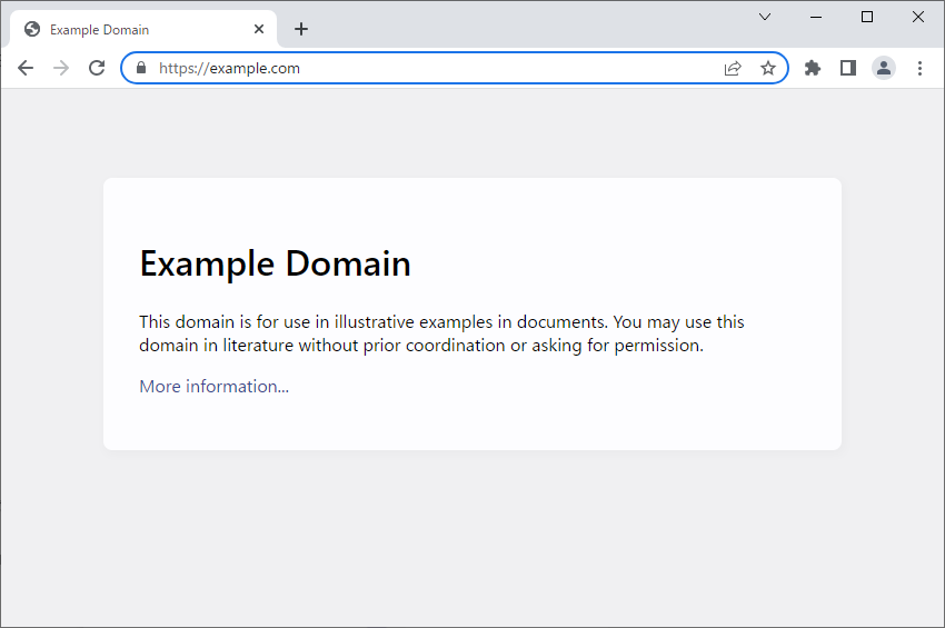
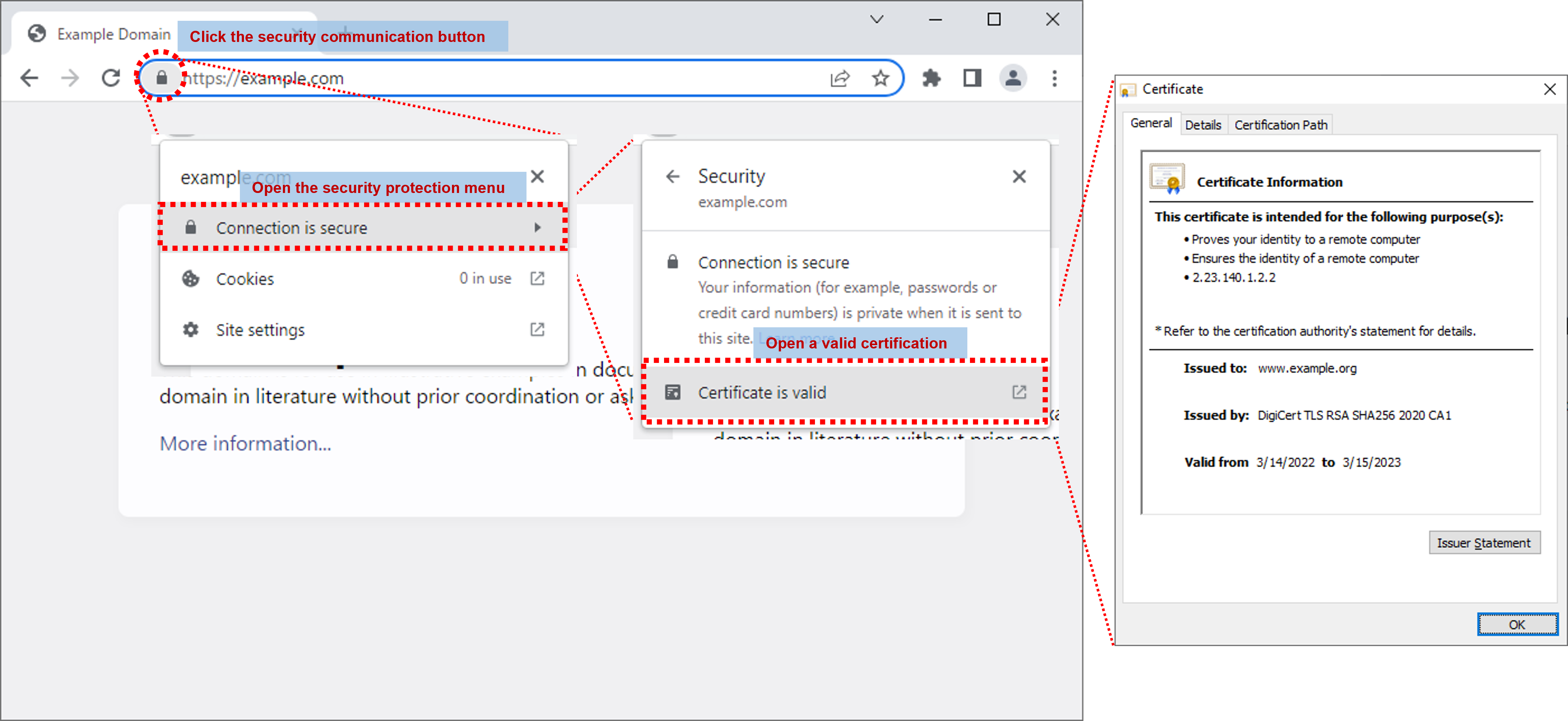
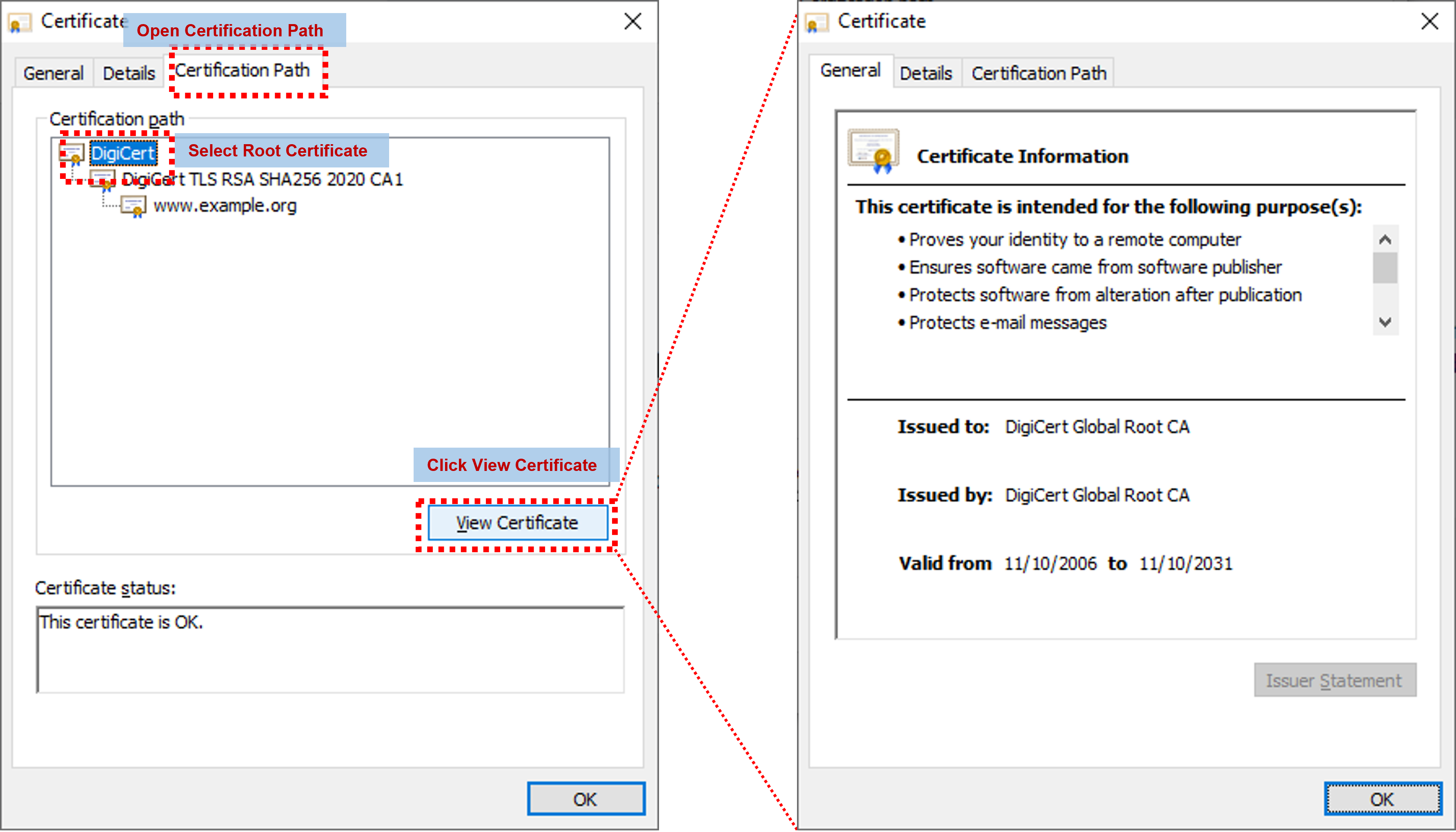
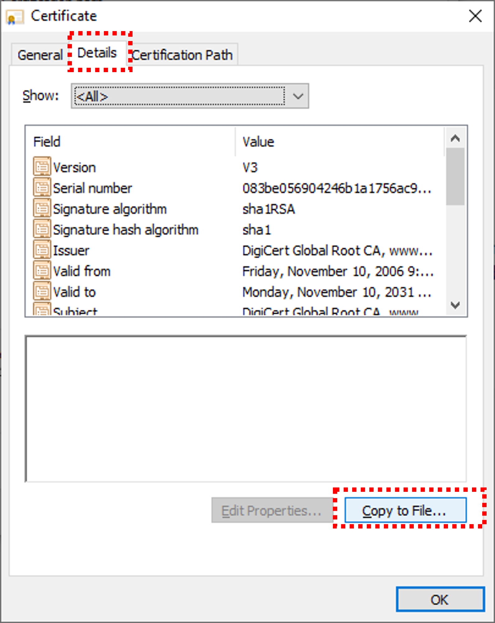
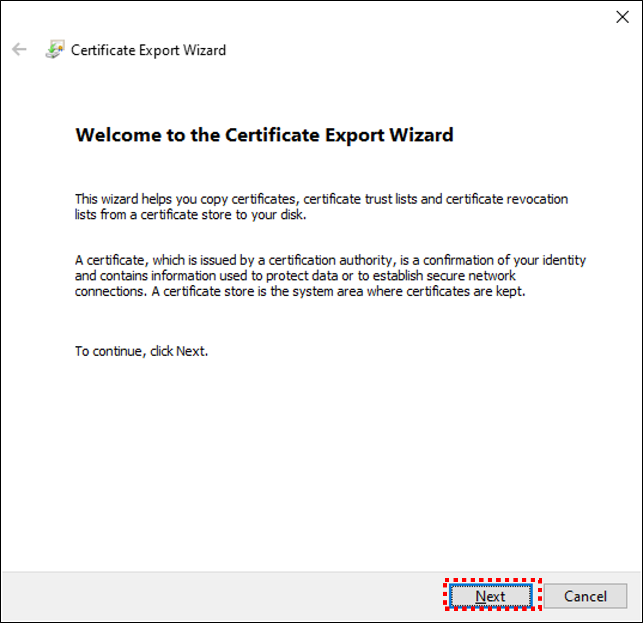
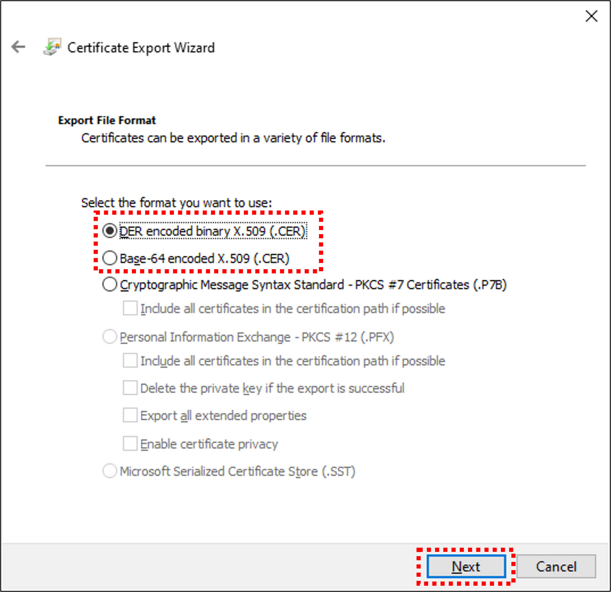
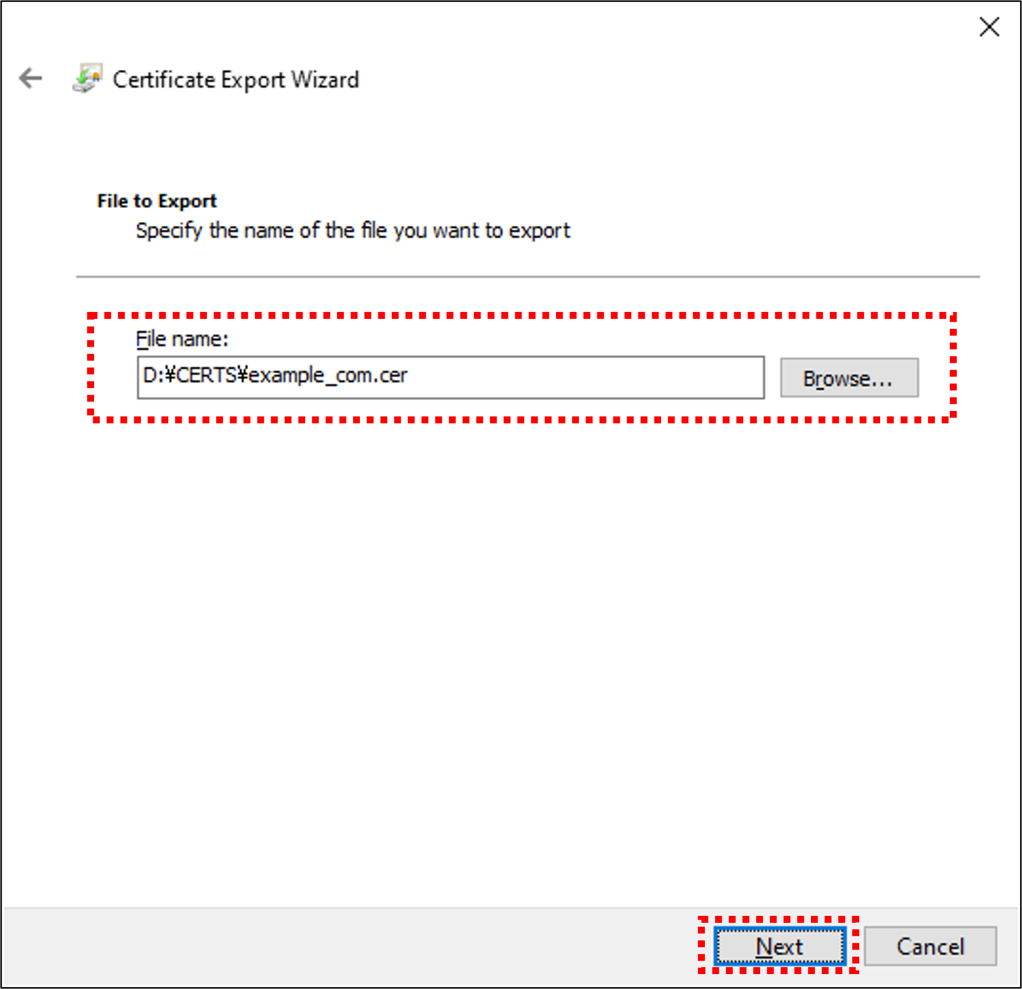
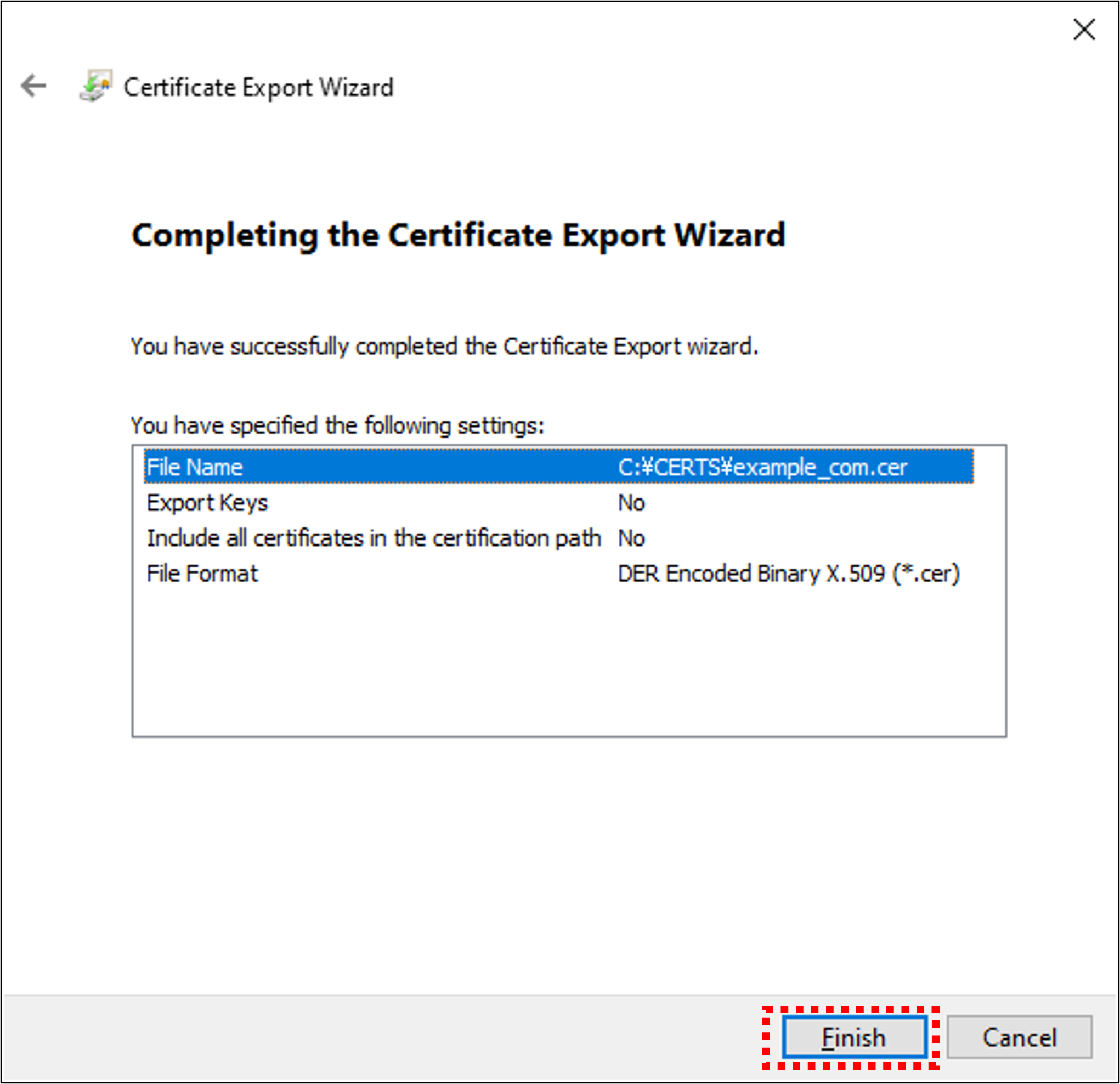
By performing the above steps, the root certificate is copied (exported). The copied root certificate can then be copied to the location specified in the application to enable secure communication with Spresense.
4. Spresense Arduino multi-core environment
This section describes the multi-core programming development environment using Arduino IDE.
In Arduino multi-core environments, please use the MultiCore MP library.
The application CPU has total of 6 cores, consisting of 1 MainCore and 5 SubCore.
In the normal single core application, the user programs only use MainCore.
In the multi-core application environment described here, you can program all cores including SubCore.
- MainCore
-
MainCore is always started at power on.
- SubCore(s)
-
SubCore(s) are launched from MainCore. There are total of 5 SubCores.
In this tutorial, we show two examples with the MultiCore MP library.
- Multicore Boot Example
-
Boot 4 SubCores and perform LED blinking using multicore.
By running this sample, you can understand the procedure to boot SubCore. - Multicore MessageHello Example
-
Communicate messages between MainCore and SubCore.
By running this sample, you can understand how to communicate between MainCore and SubCore.
4.1. Multicore Boot example
The main steps are:
-
Open a sketch using Arduino IDE
-
Select core
-
Compile & upload
Repeat above for the number of cores you want to program.
Please follow the procedure as below.
-
Launch Arduino IDE from your desktop
(If there is no icon on your desktop, please launch from the start menu etc.)
In multi-core programming, please note when you launch multiple Arduino IDE windows.
If you open a new window withFile→ Newfrom the Arduino IDE menu, if you switch the menu ofCoreselection in one window, the setting is reflected to all the windows.As a workaround, when you open multiple Arduino IDE windows for every Core, please launch Arduino IDE from the icon on your desktop. Then, menu settings such asCoreselection can be set independently for each window. -
MainCore programming
-
Open a sketch from Arduino IDE menu
File → Examples → MultiCore MP → Boot → Main.

-
Explanation for Main.ino sketch
MP.begin(subid)boot 4 SubCores.
-
Select MainCore from Arduino IDE menu
Tools → Core → MainCore.
You can see that
MainCoreis selected in the status bar.
In Arduino IDE from 1.8.9 to 1.8.13, there is an issue, the status bar is not displayed correctly after switching menu. -
Press the Upload button to do Compile & Upload.

You cannot upload multiple core programs from multiple windows at the same time.
Upload each core one by one so that the upload operation is not executed simultaneously. -
Size of used memory is displayed on the log of compilation result.
MainCore always uses 768 KByte of memory.

If Upload is successful, MainCore programming is completed.
-
As a test, try to open the serial monitor without SubCore program.
Since there is no SubCore, you can see thatMP.begin(1~4)returns error.
If the serial monitor is open, uploading from other windows may fail.
Please close the serial monitor after this trial.
-
-


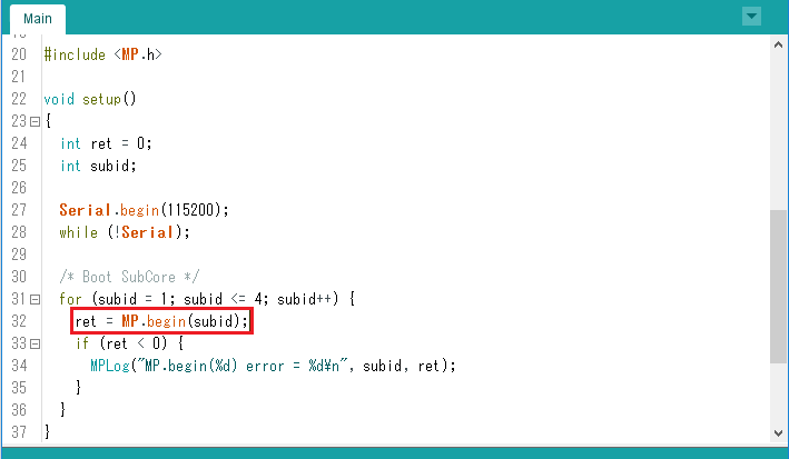


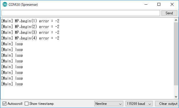
Then we will program the SubCore.
-
SubCore programming
-
Open a sketch from Arduino IDE menu
File → Examples → MultiCore MP → Boot → Sub1.

-
Explanation for Sub1.ino sketch
In setup(), by calling
MP.begin(), notify MainCore that startup is complete.
In loop(), output log byMPLog()and blink a LED.
-
Select SubCore 1 from Arduino IDE menu
Tools → Core → SubCore 1.
You can see that
SubCore 1is selected in the status bar.
In Arduino IDE from 1.8.9 to 1.8.13, there is an issue, the status bar is not displayed correctly after switching menu. -
Press the Upload button to do Compile & Upload.

You cannot upload multiple core programs from multiple windows at the same time.
Upload each core one by one so that the upload operation is not executed simultaneously. -
Size of used memory is displayed on the log of compilation result.
You can see that this SubCore sample sketch uses 128 KBytes of memory.
This size increases or decreases depending on the user program.
If Upload is successful, SubCore 1 programming is completed.
-
-
Follow the same procedure for SubCore 2, 3 and 4 and execute Compile & Upload.
-
Open Sub2 sketch, select SubCore 2, and Compile & Upload.
-
Open Sub3 sketch, select SubCore 3, and Compile & Upload.
-
Open Sub4 sketch, select SubCore 4, and Compile & Upload.
-
-
Operation check
-
Blink 4 LEDs on the Spresense main board.
-
Open the serial monitor, and you can see the log from each core.

-
-
Summary
-
We have learned how to boot SubCore using a simple example sketch.
Add a call toMP.begin()when you port an existing sketch to multi-core environment. -
The basic usage, such as Arduino IDE’s Compile & Upload method, is the same as usual in multi-core environments. The main difference is that a menu of core selections has been added in
Tools→ Core.
-


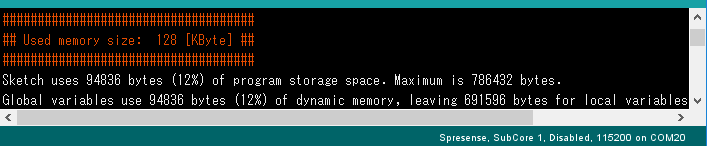

4.2. Multicore MessageHello example
The main steps are the same as Multicore Boot example.
In this example, MainCore and SubCore(s) use a common sketch.
-
Open a sketch using Arduino IDE (only once)
-
Select core
-
Compile & upload
Repeat above for the number of cores you want to program. This example runs all SubCores.
Please follow the procedure as below.
-
Launch Arduino IDE from your desktop
(If there is no icon on your desktop, please launch from the start menu etc.)
In multi-core programming, please note when you launch multiple Arduino IDE windows.
If you open a new window withFile→ Newfrom the Arduino IDE menu, if you switch the menu ofCoreselection in one window, the setting is reflected to all the windows.As a workaround, when you open multiple Arduino IDE windows for every Core, you always launch Arduino IDE from the icon on your desktop. By doing so, menu settings such asCoreselection can be set independently for each window. -
MainCore programming
-
Open a sketch from Arduino IDE menu
File → Examples → MultiCore MP → Message → MessageHello.

-
Explanation for MessageHello.ino sketch
We use
#ifdef SUBCORE~#else~#endifto switch between MainCore and SubCore implementations in this sketch.-
MainCore implementation
In setup(),
MP.begin(subid)boot 5 SubCores
By callingMP.RecvTimeout(MP_RECV_POLLING), set polling in receiver mode. In this mode, whenMP.Recv()is called, Recv() do polling with non-blocking.
In loop(),MP.Recv()receives the packet address from each SubCore, and outputs the message in the packet.
-
SubCore implementation
In setup(), by calling
MP.begin(), notify MainCore that startup is complete.
In loop(), put "Hello" message into packet, and send the packet address byMP.Send().
-
-
Select MainCore from Arduino IDE menu
Tools → Core → MainCore.
You can see that
MainCoreis selected in the status bar.
In Arduino IDE from 1.8.9 to 1.8.13, there is an issue, the status bar is not displayed correctly after switching menu. -
Press the Upload button to do Compile & Upload.

You cannot upload multiple core programs from multiple windows at the same time.
Upload each core one by one so that the upload operation is not executed simultaneously. -
Size of used memory is displayed on the log of compilation result.
MainCore always uses 768 KByte of memory.
If Upload is successful, MainCore programming is completed.
-


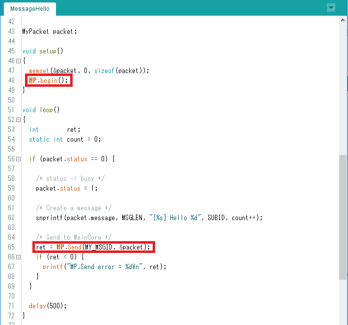


Then we will program the SubCore.
-
SubCore programming
-
Select SubCore 1 from Arduino IDE menu
Tools → Core → SubCore 1.
You can see that
SubCore 1is selected in the status bar.
In Arduino IDE from 1.8.9 to 1.8.13, there is an issue, the status bar is not displayed correctly after switching menu. -
Press the Upload button to do Compile & Upload.
You cannot upload multiple core programs from multiple windows at the same time.
Upload each core one by one so that the upload operation is not executed simultaneously. -
Size of used memory is displayed on the log of compilation result.
You can see that this SubCore sample sketch uses 128 KBytes of memory.
This size increases or decreases depending on the user program.
If Upload is successful, SubCore 1 programming is completed.
-
-
Follow the same procedure for SubCore 2, 3, 4 and 5 and execute Compile & Upload.
-
Select SubCore 2, and Compile & Upload.
-
Select SubCore 3, and Compile & Upload.
-
Select SubCore 4, and Compile & Upload.
-
-
Operation check
-
Open the serial monitor.
-
MainCore receives the message sent from each SubCore and outputs them to the serial monitor.

-
-
Summary
-
We have learned how to communicate between MainCore and SubCore.
-
It can communicate by sending the address of message because of the shared memory.
-
You can use a common sketch for multi-core programming.
-


4.3. Notices
-
See developer guide for the details of
MultiCore MPlibrary. -
If you want to remove SubCore binaries on the Spresense board, please do Install Bootloader. When installing the loader, remove all SubCore binaries and then start installing the loader.

Note that SubCore does not run unless you call
MP.begin()from MainCore. Therefore, there is no problem even if the old SubCore remains on your Spresense board. -
If you open multiple Arduino IDE windows for every
Core, please launch Arduino IDE from the icon on your desktop. Then, menu settings such asCoreselection can be set independently for each window. -
Use Arduino IDE to open multiple windows and select core is complicated, but you can use command line tools such as arduino-builder and arduino-cli. Also, you can upload the multiple binaries for all cores at once by using flash_writer tool. How to use the command line tools will be updated in this manual later.

5. Tutorial of SignalProcessing Library
The SignalProcessing library has FFT/IIR filters and the following sample sketches are provided for them.
-
FFT
-
IIR
-
FFT & IIR
This document explains how to execute these sample sketches.
5.1. PeakDetector
5.1.1. Overview
This sample sketch detects the peak frequency in real time by performing real-time frequency analysis with the FFT library on the sound data input by the microphone. Please refer to Audio library for the Audio function.
In addition, this sample performs with offloading the signal processing library to SubCore. Please see also MultiCore MP Library.
5.1.2. Operating environment
-
Spresense Main & extension Board
-
Microphones for recording
Please refer to the following hardware guide for microphone connection.
|
This sample is the multi-channels application with 4 channels. Connect microphones (up to 4@analog, 8@digital) and please adjust them within the application. |
5.1.3. Operating procedure
The main operation procedure is as follow:
-
Compile & upload SubCore for signal processing
-
Compile & upload MainCore for sound acquisition & application processing
-
Running the application
| If you compile and upload MainCore at first , it will call SubCore after startup, resulting in an error. |
| If you have already compiled and uploaded to SubCore, the program of SubCore that has already been uploaded will start after starting MainCore. |
5.1.3.1. Compilation & upload of SubCore
-
Open the sample sketch by selecting
File→ Sketch example→ Sketch example for Spresense SignalProcessing→ PeakDetector→ SubFFTfrom Arduino IDE. -
Select
Tools→ Core→ SubCore1(Tools→ Core→ SubCore1) from the Arduino IDE menu.In this sample, the offloaded SubCoreisSubCore1.
Select the COM port of Spresense with Tools→ Serial Port and write to the microcomputer board.
+
NOTE: The SubCore program waits for instructions from the MainCore after starting.
Now, the preparation on the SubCore is OK.
5.1.3.2. Compilation & upload of MainCore
-
Open the sample sketch by selecting
File→ Sketch example→ Sketch example for Spresense SignalProcessing→ PeakDetector → MainAudiofrom Arduino IDE. -
Select
Tools→ Core→ MainCore(Tools→ Core→ MainCore) from the Arduino IDE menuWrite to the microcomputer board.
If you have selected the serial port for uploading SubCore, you do not need to select it again.
|
Now, the preparation on the MainCore is also OK.
5.1.4. the Explanation of program
-
The number of input audio channels is specified in the following part of
MainAudio.ino.
/* Select mic channel number */
//const int mic_channel_num = 1;
//const int mic_channel_num = 2;
const int mic_channel_num = 4;
NOTE : #define MAX_CHANNEL_NUM 4 on the SubCore means the max number of channels is 4, user can select 1-4 channels dynamically.
This sketch calls FFT.begin(); without arguments at SubCore, so the execution number of channels on SubCore is equal to the number of maximum channels.If you don’t want the number of execution channels to be equal to the maximum number of channels, Please call FFT.begin (WindowHamming, "The number of execution channels", (FFTLEN / 2));,
and specify the number of execution channels.
|
-
The number of FFT taps is specified as follow in
SubFFT.ino.
/* Select FFT length */

//#define FFT_LEN 32
//#define FFT_LEN 64
//#define FFT_LEN 128
//#define FFT_LEN 256
//#define FFT_LEN 512
#define FFT_LEN 1024
//#define FFT_LEN 2048
//#define FFT_LEN 4096-
The current window function and the number of FFT overlap samples are set to default. The default for the window is
Hamming windowand the overlap size is designed to shift the window by the number of taps/2.
If you want to change this, please change it in the SubFFT.ino from
FFT.begin();to
FFT.begin ("window function you want to use", "number of execution channels", "number of samples you want to overlap");5.1.5. Precautions regarding changing the number of TAPs
When changing the number of FFT TAPs, the following precautions are required regarding the CPU processing performance and SubCore memory usage for real-time processing.
-
If you want to set the number of TAPs to 4096.
If you want to operate on 4 channels, you should change it in SubFFT.ino from
USER_HEAP_SIZE (64 * 1024);To
USER_HEAP_SIZE (64 * 1024 * 5);In this case, default SubCore memory will not be enough,
so you need to select Tools→ Memory→ 640kB from the Arduino IDE to set the MainCore memory size to 640kB.
If you want to operate on 2 channels, you do not need to change MainCore memory size, and only change it in SubFFT.ino to
USER_HEAP_SIZE(64 * 1024 * 4);-
If you want to set the number of TAPs to 2048.
You should change it in SubFFT.ino from
USER_HEAP_SIZE (64 * 1024);To
USER_HEAP_SIZE (64 * 1024 * 4);-
If you want to set the number of TAPs to 256.
Due to the display performance conditions on the MainCore side, only up to 2 channels can be operated.
5.2. SoundDetector
5.2.1. Overview
This sample sketch uses the FFT library for real-time frequency analysis of the sound data input by the microphone, and detects whether sound with a certain sound pressure level is input within the specified frequency range. Please refer to Audio library for the Audio function.
In addition, this sample performs with offloading the signal processing library to SubCore. Please see also MultiCore MP Library.
5.2.2. Operating environment
-
Spresense Main & extension Board
-
Microphones for recording
Please refer to the following hardware guide for microphone connection.
|
This sample is the multi-channels application with 4 channels. Connect microphones (up to 4@analog, 8@digital) and please adjust them within the application. |
5.2.3. Operating procedure
The main operation procedure is as follow:
-
Compile & upload SubCore for signal processing
-
Compile & upload MainCore for sound acquisition & application processing
-
Running the application
| If you compile and upload MainCore at first , it will call SubCore after startup, resulting in an error. |
| If you have already compiled and uploaded to SubCore, the program of SubCore that has already been uploaded will start after starting MainCore. |
5.2.3.1. Compilation & upload of SubCore
-
Open the sample sketch by selecting
File→ Sketch example→ Sketch example for Spresense SignalProcessing→ SoundDetector → SubFFTfrom Arduino IDE. -
Select
Tools→ Core→ SubCore1(Tools→ Core→ SubCore1) from the Arduino IDE menu.In this sample, the offloaded SubCoreisSubCore1. -
Select the COM port of Spresense with
Tools→ Serial Portand write to the microcomputer board.The SubCoreprogram waits for instructions from theMainCoreafter starting.
Now, the preparation on the SubCore is OK.
5.2.3.2. Compilation & upload of MainCore
-
Open the sample sketch by selecting
File→ Sketch example→ Sketch example for Spresense SignalProcessing→ SoundDetector→ MainAudiofrom Arduino IDE. -
Select
Tools→ Core→ MainCore(Tools→ Core→ MainCore) from the Arduino IDE menuWrite to the microcomputer board.
If you have selected the serial port for uploading SubCore, you do not need to select it again.
|
Now, the preparation on the MainCore is also OK.
5.2.3.3. Run the application
-
After uploading
MainCore, openTools→ Serial Monitorand start the application. -
When the application is started, frequency analysis is performed on the sound of each channel input from the microphone, and if sound with more than specified sound power is input within the specified frequency range, it shows the detection and channel numbernel number like
> Found channel 0.
5.2.4. the Explanation of program
-
The number of input audio channels is specified in the following part of
MainAudio.ino.
/* Select mic channel number */
//const int mic_channel_num = 1;
//const int mic_channel_num = 2;
const int mic_channel_num = 4;
NOTE : #define MAX_CHANNEL_NUM 4 on the SubCore means the max number of channels is 4, user can select 1-4 channels dynamically.
This sketch calls FFT.begin(); without arguments at SubCore, so the execution number of channels on SubCore is equal to the number of maximum channels.If you don’t want the number of execution channels to be equal to the maximum number of channels, Please call FFT.begin (WindowHamming, "The number of execution channels", (FFTLEN / 2));,
and specify the number of execution channels.
|
-
The number of FFT taps is specified as follow in
SubFFT.ino.
/* Select FFT length */

//#define FFT_LEN 32
//#define FFT_LEN 64
//#define FFT_LEN 128
//#define FFT_LEN 256
//#define FFT_LEN 512
#define FFT_LEN 1024
//#define FFT_LEN 2048
//#define FFT_LEN 4096-
The current window function and the number of FFT overlap samples are set to default. The default is the window is
Hamming windowand the overlap size is designed to shift the window by the number of taps/2.
If you want to change this, please change it in the SubFFT.ino from
FFT.begin();to
FFT.begin ("window function you want to use", "number of execution channels", "number of samples you want to overlap");-
The detector settings are as follow:
#define POWER_THRESHOLD 30 // Power
#define LENGTH_THRESHOLD 30 // 20ms
#define INTERVAL_THRESHOLD 100 // 100ms

#define BOTTOM_SAMPLING_RATE 1000 // 1kHz
#define TOP_SAMPLING_RATE 1500 // 1.5kHz-
Specify the lower limit of frequency range for the detection with
BOTTOM_SAMPLING_RATE. Set the Hz value. -
Specify the upper limit of frequency range for the detection with
TOP_SAMPLING_RATE. Set the Hz value. -
Specify the threshold of the sound power for the detection with
POWER_THRESHOLD. -
If audio in the relevant frequency range continues to be input for more than
LENGTH_THRESHOLDtime, it is judged that the sound is detected. -
If it is re-detected within
INTERVAL_THRESHOLDafter being detected, it is considered to be a part of the previously detected sound. Also, if it is detected more thanINTERVAL_THRESHOLDaway, another sound is detected and the notification is raised toMainCoreagain.
5.2.5. Precautions regarding changing the number of TAPs
When changing the number of FFT TAPs, the following precautions are required regarding the CPU processing performance and SubCore memory usage for real-time processing.
-
If you want to set the number of TAPs to 4096.
If you want to operate on 4 channels, you should change it in SubFFT.ino from
USER_HEAP_SIZE (64 * 1024);To
USER_HEAP_SIZE (64 * 1024 * 5);In this case, SubCore memory will not be enough on default,
so you need to select Tools→ Memory→ 640kB from the Arduino IDE to set the MainCore memory size to 640kB.
If you want to operate on 2 channels, you do not need to change MainCore memory size, and only change it in SubFFT.ino from
USER_HEAP_SIZE (64 * 1024);to
USER_HEAP_SIZE(64 * 1024 * 4);-
If you want to set the number of TAPs to 2048.
You should change it in SubFFT.ino from
USER_HEAP_SIZE (64 * 1024);To
USER_HEAP_SIZE (64 * 1024 * 4);5.3. LowPassSound
5.3.1. Overview
This sample sketch outputs the sound data that is LPF (low-pass filter) by IIR.
In addition, this sample performs with offloading the signal processing library to SubCore. Please see also MultiCore MP Library.
5.3.2. Operating environment
-
Spresense Main & extension Board
-
Headphones or speakers for playback
-
Microphones for recording
In this sample, headphones and a microphone are used.
Please connect headphones or active speakers to the headphone jack on the extension board.
Please refer to the following hardware guide for microphone connection.
| The samples provided are for a monorail microphone. If you want more microphones, Connect microphones (up to 4@analog, 8@digital) and please adjust them within the application. |
| Audio output can only be up to stereo. If the input is 3 channels or more, perform downmix processing before output, convert to 2 channels data. |
5.3.3. Operating procedure
The main operation procedure is as follow:
-
Compile & upload SubCore for signal processing
-
Compile & upload MainCore for sound acquisition & application processing
-
Running the application
| If you compile and upload MainCore at first, it will call SubCore after startup, resulting in an error. |
| If you have already compiled and uploaded to SubCore, the program of SubCore that has already been uploaded will start after starting MainCore. |
5.3.3.1. Compilation & upload of SubCore
-
Open the sample sketch by selecting
File→ Sketch example→ Sketch example for Spresense SignalProcessing→ HighPassSound / LowPassSound→ SubFFTfrom Arduino IDE. -
Select
Tools→ Core→ SubCore1(Tools→ Core→ SubCore1) from the Arduino IDE menu.In this sample, the offloaded SubCoreisSubCore1. -
Select the COM port of Spresense with
Tools→ Serial Portand write to the microcomputer board.The SubCoreprogram waits for instructions from theMainCoreafter starting.
Now, the preparation on the SubCore is OK.
5.3.3.2. Compilation & upload of MainCore
-
Open the sample sketch by selecting
File→ Sketch example→ Sketch example for Spresense SignalProcessing→ LowPassSound → MainAudiofrom Arduino IDE. -
Select
Tools→ Core→ MainCorefrom the Arduino IDE menuWrite to the microcomputer board.
If you have selected the serial port for uploading SubCore, you do not need to select it again.
|
Now, the preparation on the MainCore is also OK.
5.3.4. the Explanation of program
-
The number of input audio channels is specified in the following part of
MainAudio.ino.
static const int32_t channel_num  = AS_CHANNEL_MONO;
static const int32_t bit_length   = AS_BITLENGTH_16;
static const int32_t frame_sample = 768;| Only the 16 bit mode is supported for bit length. |
The number of channels and the number of frame samples must match the SubCore side.
|
|
When outputting audio, it must be converted to interleaved stereo data. Therefore, in this sample, after signal processing, monaural data is converted to stereo data. |
-
The cutoff frequency and Q value are set by the following part of
SubCore.
const int   g_channel = 1; /* Number of channels */
const int   g_cutoff  = 1000; /* Cutoff frequency */
const float g_Q       = sqrt(0.5); /* Q Value */
In this sample, the cutoff frequency is set to 1kHz and the Q value is set to sqrt(0.5) .
If nothing is specified with the number of samples, the number of samples in the output frame will be the default value of 768 samples.
If nothing is specified with the sampling rate, the sampling rate will be the default value of 48kHz.
If you do not specify an output format, the default format is per-channel output Planar.
|
In this sample, sound is collected by FrontEndObject. Due to HW restrictions, Spresense’s audio function uses 48kHz sampling or 192kHz sampling for all input and output. When realizing an input / output application that involves audio signal processing, if internal processing is performed at a sampling rate such as 16kHz, resampling with SW is required twice, which requires a lot of processor power and memory. In the case of real time audio processing using the IIR filter this time, processing at 16KHz is not recommended due to insufficient memory. |
-
When acquiring data after signal processing, if the output format is
Planar, callgetmultiple times for the number of channels to acquire the multi channel data.
    for (int i = 0; i < g_channel; i++) {
      cnt = LPF.get(pDst, i);
      /* Channels must be stereo for Mixer */
      if(i == 0) {
        for(int j = 0; j < cnt; j++) {
          out_buffer[pos][j * 2]     = pDst[j];
          out_buffer[pos][j * 2 + 1] = 0;
        }
      }
    }
It is necessary to get areas for each channel to write multi channel data.
|
| In order to output audio, this sample is converted to interleaved stereo data. In this sample, the R channel is generated with 0. |
5.4. HighPassSound
5.4.1. Overview
This sample sketch outputs the sound data that is perform HPF (high-pass filter) by IIR.
In addition, this sample performs with offloading the signal processing library to SubCore. Please see also MultiCore MP Library.
5.4.2. Operating environment
-
Spresense Main & extension Board
-
Headphones or speakers for playback
-
Microphones for recording
In this sample, headphones and a microphone are used.
Please connect headphones or active speakers to the headphone jack on the extension board.
Please refer to the following hardware guide for microphone connection.
| The samples provided are for a monorail microphone. If you want more microphones, Connect microphones (up to 4@analog, 8@digital) and please adjust them within the application. |
| Audio output can only be up to stereo. If the input is 3 channels or more, perform downmix processing before output, convert to 2 channels data. |
5.4.3. Operating procedure
The main operation procedure is as follow:
-
Compile & upload SubCore for signal processing
-
Compile & upload MainCore for sound acquisition & application processing
-
Running the application
| If you compile and upload MainCore at first, it will call SubCore after startup, resulting in an error. |
| If you have already compiled and uploaded to SubCore, the program of SubCore that has already been uploaded will start after starting MainCore. |
5.4.3.1. Compilation & upload of SubCore
-
Open the sample sketch by selecting
File→ Sketch example→ Sketch example for Spresense SignalProcessing→ HighPassSound / LowPassSound→ SubFFTfrom Arduino IDE. -
Select
Tools→ Core→ SubCore1(Tools→ Core→ SubCore1) from the Arduino IDE menu.In this sample, the offloaded SubCoreisSubCore1. -
Select the COM port of Spresense with
Tools→ Serial Portand write to the microcomputer board.The SubCoreprogram waits for instructions from theMainCoreafter starting.
Now, the preparation on the SubCore is OK.
5.4.3.2. Compilation & upload of MainCore
-
Open the sample sketch by selecting
File→ Sketch example→ Sketch example for Spresense SignalProcessing→ HighPassSound → MainAudiofrom Arduino IDE. -
Select
Tools→ Core→ MainCorefrom the Arduino IDE menuWrite to the microcomputer board.
If you have selected the serial port for uploading SubCore, you do not need to select it again.
|
Now, the preparation on the MainCore is also OK.
5.4.4. the Explanation of program
-
The number of input audio channels and the number of processing frame samples are specified in the following part of
MainAudio.ino.
static const int32_t channel_num  = AS_CHANNEL_STEREO;
static const int32_t bit_length   = AS_BITLENGTH_16;
static const int32_t frame_sample = 240;
In this sample, the number of channels is set to 2ch and the number of processing frame samples is set to 240.
| Only the 16 bit mode is supported for bit length. |
The number of channels and the number of processing frame samples must match the SubCore side.
|
|
In this sample, the number of processing frame samples is 240. Reducing the number of frame samples reduces the latency of audio processing, but increases the processing load on the CPU. |
-
The cutoff frequency and Q value are set by the following part of
SubCore.
const int   g_channel = 2; /* Number of channels */
const int   g_cutoff  = 1000; /* Cutoff frequency */
const float g_Q       = sqrt(0.5); /* Q Value */
const int   g_sample  = 240; /* Number of channels */
const int   g_fs      = 48000; /* Sampling Rate */
In this sample, the cutoff frequency is set to 1kHz, the Q value is set to 1 / √2, the number of output frame samples is set to 240, and the sampling rate is set to 48kHz.
And,
if (! HPF.begin (TYPE_HPF, g_channel, g_cutoff, g_Q, g_sample, IIRClass :: Interleave, g_fs)) {The output format is specified as Interleave.
|
In this sample, sound is collected by FrontEndObject. Due to HW restrictions, Spresense’s audio function uses 48kHz sampling or 192kHz sampling for all input and output. When realizing an input / output application that involves audio signal processing, if internal processing is performed at a sampling rate such as 16kHz, resampling with SW is required twice, which requires a lot of processor power and memory. In the case of real time audio processing using the IIR filter this time, processing at 16KHz is not recommended due to insufficient memory. |
5.5. VoiceChanger
5.5.1. Overview
This sample sketch performs FFT / iFFT on the voice data input by the microphone to change the pitch and regenerate the voice data. The LP filter is applied to the generated data to cut off the high frequency noise added due to the lack of phase information, etc., and then output. Please refer to Audio library for the Audio function.
In addition, this sample performs with offloading the signal processing library to SubCore. Please see also MultiCore MP Library.
| This sample is provided as a simple FFT/iFFT execution sample. Therefore, it is not good for the sound quality as a pitch shifter. |
5.5.2. Operating environment
-
Spresense Main & extension Board
-
Headphones or speakers for playback
-
Microphones for recording
In this sample, headphones and a microphone are used.
Please connect headphones or active speakers to the headphone jack on the extension board.
Please refer to the following hardware guide for microphone connection.
| The samples provided are for a monorail microphone. If you want more microphones, Connect microphones (up to 4@analog, 8@digital) and please adjust them within the application. |
| Audio output can only be up to stereo. If the input is 3 channels or more, perform downmix processing before output, convert to 2 channels data. |
5.5.3. Operating procedure
The main operation procedure is as follow:
-
Compile & upload SubCore for signal processing
-
Compile & upload MainCore for sound acquisition & application processing
-
Running the application
| If you compile and upload MainCore at first , it will call SubCore after startup, resulting in an error. |
| If you have already compiled and uploaded to SubCore, the program of SubCore that has already been uploaded will start after starting MainCore. |
5.5.3.1. Compilation & upload of SubCore
-
Open the sample sketch by selecting
File→ Sketch example→ Sketch example for Spresense SignalProcessing→ VoiceChanger→ SubFFTfrom Arduino IDE. -
Select
Tools→ Core→ SubCore1(Tools→ Core→ SubCore1) from the Arduino IDE menu.In this sample, the offloaded SubCoreisSubCore1. -
Select the COM port of Spresense with
Tools→ Serial Portand write to the microcomputer board.The SubCoreprogram waits for instructions from theMainCoreafter starting.
Now, the preparation on the SubCore is OK.
5.5.3.2. Compilation & upload of MainCore
-
Open the sample sketch by selecting
File→ Sketch example→ Sketch example for Spresense SignalProcessing→ VoiceChanger → MainAudiofrom Arduino IDE. -
Select
Tools→ Core→ MainCore(Tools→ Core→ MainCore) from the Arduino IDE menuWrite to the microcomputer board.
If you have selected the serial port for uploading SubCore, you do not need to select it again.
Now, the preparation on the MainCore is also OK.
5.5.3.3. Run the application
-
After uploading
MainCore, openTools→ Serial Monitorand start the application. -
When the application is started, the data in the frequency domain obtained by FFT is processed into the audio data input from the microphone, the data with the changed pitch is reconstructed with iFFT and output.
5.5.4. the Explanation of program
-
The number of input audio channels and the number of processing frame samples are specified in the following part of
MainAudio.ino.
static const int32_t channel_num  = AS_CHANNEL_MONO;
static const int32_t bit_length   = AS_BITLENGTH_16;
static const int32_t frame_sample = 1024;| Only the 16 bit mode is supported for bit length. |
The number of channels and the number of processing frame samples must match the SubCore side.
|
|
In this sample, the number of processing frame samples is 1024. Please specify according to the pipeline configuration based on the number of FFT TAPs. |
|
When outputting audio, it must be converted to interleaved stereo data. Therefore, in this sample, after signal processing, monaural data is converted to stereo data and output. |
-
The amount of pitch shift is specified below in
MainAudio.ino
static int pitch_shift = -10;
It can be shifted in the positive and negative directions according to the resolution of the FFT.
In this sample, 1024TAP FFT / iFFT processing is performed on the 48kHz sampled audio data, so about 46Hz is changed in one shift.
This parameter can be changed even during signal processing operation.
-
The number of FFT taps is specified as follow in
SubFFT.ino.
/* Select FFT length */

//#define FFT_LEN 32
//#define FFT_LEN 64
//#define FFT_LEN 128
//#define FFT_LEN 256
//#define FFT_LEN 512
#define FFT_LEN 1024
//#define FFT_LEN 2048
//#define FFT_LEN 4096-
This sample regenerates the audio with FFT/iFFT, so it is
rectangular windowand no overlap.
FFT.begin(WindowRectangle,MAX_CHANNEL_NUM,0);If you want to change the algorithm, please change accordingly.
-
The LPF setting value after iFFT is below
const int g_channel = MAX_CHANNEL_NUM; / * Number of channels * /
const int g_cutoff = 1000; / * Cutoff frequency * /
const float g_Q = sqrt (0.5); / * Q Value * /
const int g_sample = 1024; / * Number of channels * /

const int g_max_shift = 30; / * Pitch shift value * /
The cutoff frequency is set to 1kHz and the Q value is set to 1 / √2, but change accordingly.
Since it is a monaural input, the output format is the default Planar.
|
-
Maximum shift value is specified below.
const int g_max_shift = 30; / * Pitch shift value * /This sample is set to 30.
-
The output audio data is converted to interleaved stereo data here.
        for (int j = 0; j <cnt; j ++) {
          pOut [pos] [j * 2] = pLpfDst [j];
          pOut [pos] [j * 2 + 1] = 0;
        }
In this sample, the R channel is generated with 0.
|
In this sample, sound is collected by FrontEndObject. Due to HW restrictions, Spresense’s audio function uses 48kHz sampling or 192kHz sampling for all input and output. When supporting an input / output application that involves audio signal processing, if internal processing is performed at a sampling rate such as 16kHz, resampling with SW is required twice, which requires a lot of processor power and memory. In the case of real time audio processing using the IIR filter this time, processing at 16KHz is not recommended due to insufficient memory. |