
1. Spresense Arduino Sketch App Development
To quickly get started writing sketches you can use the example files. These examples are included in the Spresense Arduino Library and are available at File > Examples > Spresense.
Many existing Arduino sketches and libraries run on Spresense. Some of these sketches are for different hardware. You will need to modify these sketches. For an overview of the hardware features, see Differences between Spresense and Arduino Uno.
1.1. Functional Differences
The following Arduino language functions behave differently on Spresense and Arduino Uno:
- LEDs
-
The Spresense main board has 4 LEDs:
LED0,LED1,LED2, andLED3.LED0can also be addressed using the nameLED_BUILTINfor compatibility with existing sketches.To control the LEDs, configure the LED as an output using
pinMode()and calldigitalWrite(). - EEPROM
-
The Spresense doesn’t have EEPROM, but the EEPROM library emulates EEPROM using the flash memory. If you want to handle persistent data, you can use the EEPROM library or the SD card on the extension board.
- Serial
-
The Spresense has two UART serial ports. You can access these ports with the Arduino SDK. The main board’s USB port is addressed as
Serialand the logic-level pinsDO0andDO1are addressed asSerial2.The main board USB serial port can be used for your application, but be aware that it is also used to provide error messages from the NuttX operating system. These can be helpful in debugging your sketch.
The second parameter, like Serial.begin(115200, SERIAL_8E1), allows you to set the data length, the parity, and the stop bit. If the argument is none, the default value is
SERIAL_8N1with 8 bits of data length, no parity and 1 stop bit.Parameter Data length Parity Stop bit SERIAL_5N1
5
none
1
SERIAL_6N1
6
none
1
SERIAL_7N1
7
none
1
SERIAL_8N1
8
none
1
SERIAL_5N2
5
none
2
SERIAL_6N2
6
none
2
SERIAL_7N2
7
none
2
SERIAL_8N2
8
none
2
SERIAL_5E1
5
even
1
SERIAL_6E1
6
even
1
SERIAL_7E1
7
even
1
SERIAL_8E1
8
even
1
SERIAL_5E2
5
even
2
SERIAL_6E2
6
even
2
SERIAL_7E2
7
even
2
SERIAL_8E2
8
even
2
SERIAL_5O1
5
odd
1
SERIAL_6O1
6
odd
1
SERIAL_7O1
7
odd
1
SERIAL_8O1
8
odd
1
SERIAL_5O2
5
odd
2
SERIAL_6O2
6
odd
2
SERIAL_7O2
7
odd
2
SERIAL_8O2
8
odd
2
Also,
Serial2supports hardware flow control. Hardware flow control is enabled by addingSERIAL_RTSCTSlike Serial2.begin(115200, SERIAL_8N1 | SERIAL_RTSCTS). If the argument is none, hardware flow control is disabled by default.Even if hardware flow control is disabled, you cannot use the UART2_RTSandUART2_CTSpins as GPIO.Parameter Description SERIAL_CTS
Enable CTS hardware flow control
SERIAL_RTS
Enable RTS hardware flow control
SERIAL_RTSCTS
Enable RTS/CTS hardware flow control
pinMode()-
The extension board has pull-ups on all pins. This can alter the logic for some designs.
-
At startup all pins are pulled up.
-
When pins are set to input, they are pulled up. This can impact circuits with a pull-down resistor.
-
When the pin is set to output,
digitalWrite()will be set, whether the pin is high or low.
pinMode()sets the specified pin to GPIO mode, but note that the mode setting is controlled in units of pin groups. For example, in the case of SPI, the 4 pinsCS,SCK,MOSI, andMISObelong to the same group, and ifpinMode()specified as the argument ofCSpin is called, it will not be able to operate as the SPI function. For more information about the pin groups, see Connector pin list (xlsx). -
analogRead()-
Spresense has 6 dedicated analog pins. These pins are not shared with digital pins. They must be addressed as A0 to A5.
Channel A0 to A3 are slower ADCs with a sample rate of about 65 Hz. Channel A4 and A5 are faster ADC with a sample rate of about 6 kHz.
For advanced users higher ADC performance can be achieved using the Spresense SDK.
-
analogReadMap()[extended] -
The analogRead() function gets a signed 16-bit value (signed short) from the ADC and maps it to a value between 0 and 1023 using the map(value, fromLow, fromHigh, toLow, toHigh) function.
The analogReadMap() function allows you to change the
fromLowandfromHighused for the map() function. Also, ifminandmaxof analogReadMap() are set to the same value, the analogRead() function will return the raw ADC value without any conversion by map().APIvoid analogReadMap(uint8_t pin, int16_t min, int16_t max);Parameterpin: 0 ~ 5 or A0 ~ A5 analog pin number
min: the value of fromLow used for map() function
max: the value of fromHigh used for map() function analogReference()-
analogReference()is not supported. The reference voltage for analog input use for Spresense is fixed. F()-
The Arduino F() macro is defined as Null, the function does nothing. This allows existing code using F() compile without error.
PROGMEM-
The Arduino function PROGMEM() is defined as Null, the function does nothing. This allows existing code using PROGMEM() compile without error.
- Interrupts - Digital pin
-
The interrupt number for the digital pin is dynamically assigned within the
attachInterrupt()function.attachInterrupt (pin, ISR, mode, filter=true);Where
pin-
the pin number, for example D05.
ISR-
the ISR to call when the interrupt occurs; this function must take no parameters and return nothing. This function is sometimes referred to as an interrupt service routine.
mode-
defines when the interrupt should be triggered. Four constants are predefined as valid values:
LOW to trigger the interrupt whenever the pin is low,
CHANGE to trigger the interrupt whenever the pin changes value
RISING to trigger when the pin goes from low to high,
FALLING for when the pin goes from high to low.
HIGH to trigger the interrupt whenever the pin is high.
filter-
defines if a debounce filter is enabled or not. The debounce filter has been implemented for digital pin interrupts. This introduces a short delay and prevents a second interrupt occurring within 3 RTC (32.768 kHz) cycles (about 100us) of the first interrupt. Therefore, interrupts may not be acquired for signals which change very rapidly.
true Enable the debounce filter. (default)
false Disable the debounce filter.
digitalPinToInterrupt()is defined as an empty macro, to retain compatibility with existing code and can be used in the following way.attachInterrupt (digitalPinToInterrupt (pin), ISR, mode);digitalPinToInterrupt (pin)should not be used in the formx = digitalPinToInterrupt (pin); attachInterrupt (x, ISR, mode);The maximum number of interrupts that can be registered is fixed, and up to 6 interrupts can be registered from the SYS GPIO group and up to 6 interrupts can be registered from the APP GPIO group, up to 12 interrupts in total. When
attachInterrupt()is called beyond the upper limit, the error messageERROR: Out of interrupt resourceswill be displayed on the serial monitor. See below for which group each pin number belongs to in SYS/APP GPIO.-
Up to 6 pins from SYS GPIO (LTE library uses one pin for modem operation.)
D02, D03, D04, D05, D06, D07, D08, D09, D14, D15, D22, D29, D30, D31, D32, D39, D40, D41, D42, D43, D44
-
Up to 6 pins from APP GPIO (One pin is used for SD card detection.)
D00, D01, D10, D11, D12, D13, D16, D17, D18, D19, D20, D21, D23, D24, D25, D26, D27, D28, D33, D34, D35, D36, D37, D38
- Interrupts - Timer
-
Timer interrupts can be implemented using
attachTimerInterrupt(ISR,period). This function uses the same timer resource as tone (), so it can not be used with tone () at the same time.Where
ISR-
the ISR to call when the interrupt occurs; this function must return the next timer period in microseconds. If this function returns 0, the timer stops and it behaves as oneshot timer. The maximum value is about 26 seconds and if it exceeds, an error occurs.
period-
defines the timer period in microseconds after the attachTimerInterrupt.
Since this function is called from an interrupt handler, there are restrictions on callable API. For example, you can not use the Analog I / O function from within this function
micros()-
micros() returns the elapsed time in microseconds since the power was turned on.
The resolution of the
micros()timer is approximately 30 microseconds. It is based on a 32768 Hz oscillator.APIuint64_t micros(void);ReturnsThe return value is an unsigned 64-bit integer.
millis()-
millis() returns the elapsed time in milliseconds since the power was turned on.
APIuint64_t millis(void);ReturnsThe return value is an unsigned 64-bit integer.
- Fast digital I/O
-
Apart from the usual
digitalReadanddigitalWritefunctions, this section describes functions for faster I/O control of digital pins.Function Description digitalPinToPort(pin)
uint8_t port = digitalPinToPort(PIN_Dxx);
It converts a PIN_Dxx digital pin number to a port number and is used as an argument of portRegister function.portInputRegister(port)
volatile uint8_t *in = portInputRegister(digitalPinToPort(PIN_Dxx));
Inputs the port number converted by the digitalPinToPort function, and returns the GPIO input register.
The value read from the register indicates 0: Low, 1: High.portOutputRegister(port)
volatile uint8_t *out = portOutputRegister(digitalPinToPort(PIN_Dxx));
Inputs the port number converted by the digitalPinToPort function, and returns the GPIO output register.
The value to be written to the register is 0: Low, 1: High.portModeRegister(port)
volatile uint8_t *mode = portModeRegister(digitalPinToPort(PIN_Dxx));
Inputs the port number converted by the digitalPinToPort function, and returns the GPIO direction register.
The value to be written to the register is 0: Output, 1: Input.
In addition to this register control, the pin function needs to be set to GPIO mode. Therefore,
- call pinMode(PIN_Dxx, INPUT) when the pin is used as input pin
- call pinMode(PIN_Dxx, OUTPUT) when the pin is used as output pindigitalPinToBitMask(pin)
uint8_t mask = digitalPinToBitMask(PIN_Dxx);
Always returns a fixed value of 0x01.
The Input, Output, and Mode registers are all controlled using the least significant bit (0x01).Example of reading the input value of PIN_D22 pin/* Set pin to input mode */ pinMode(PIN_D22, INPUT); volatile uint8_t *port = portInputRegister(digitalPinToPort(PIN_D22)); volatile uint8_t *mode = portModeRegister(digitalPinToPort(PIN_D22)); *mode = 1; /* Input setting */ uint8_t val = *port; /* Read */ if (val & 1) Serial.println("High"); else Serial.println("Low");Example of changing the output value of the PIN_LED0 pin/* Set pin to output mode */ pinMode(PIN_LED0, OUTPUT); volatile uint8_t *port = portOutputRegister(digitalPinToPort(PIN_LED0)); volatile uint8_t *mode = portModeRegister(digitalPinToPort(PIN_LED0)); *mode = 0; /* Output setting */ *port = 1; /* High */ *port = 0; /* Low */
1.2. Spresense Libraries
The Spresense Arduino Library also provides a range of built-in libraries. These are described in the Spresense Arduino Libraries section.
1.3. Memory Usage
As a feature of Spresense, the compiled sketch is installed into the flash memory. When it is executed, all the data including complied code and read-only data, are copied from the flash memory to the RAM and executed from the RAM.
The maximum RAM available is 768 kilobytes (= 786432 bytes) by default. Which is half of the size of application SRAM of 1.5 MB.
If the program size of sketch exceeds the available maximum RAM size, the compilation will fail and an error will occur.
A memory usage report is generated when you compile a sketch on the Arduino IDE. This report allows you to check the memory consumption. For example:
Sketch uses xxxxxx bytes (xx%) of program storage space. Maximum is 786432 bytes.
Global variables use xxxxxx bytes (xx%) of dynamic memory, leaving xxxxxx bytes for local variables. Maximum is 786432 bytes.
In this report, some terms have different meaning from the original.
program storage space-
it means the available maximum RAM size.
dynamic memory-
it means the static RAM size used by a sketch.
local variables-
it means the remaining RAM size (=
program storage space-dynamic memory)
There is a dynamically allocated heap area besides the statically used memory.
This heap area is allocated from the remaining RAM called local variables.
Therefore, when you program a sketch, it is necessary to leave the remaining RAM size for the heap area.
If the size used by a sketch exceeds 75% of the total, a warning message of Low memory available, stability problems may occur.
will be generated as a guide. Then, you can review the memory size used by the sketch program.
1.4. Arduino memory size configuration
A typical memory configuration for the application SRAM 1.5 MByte is shown below.
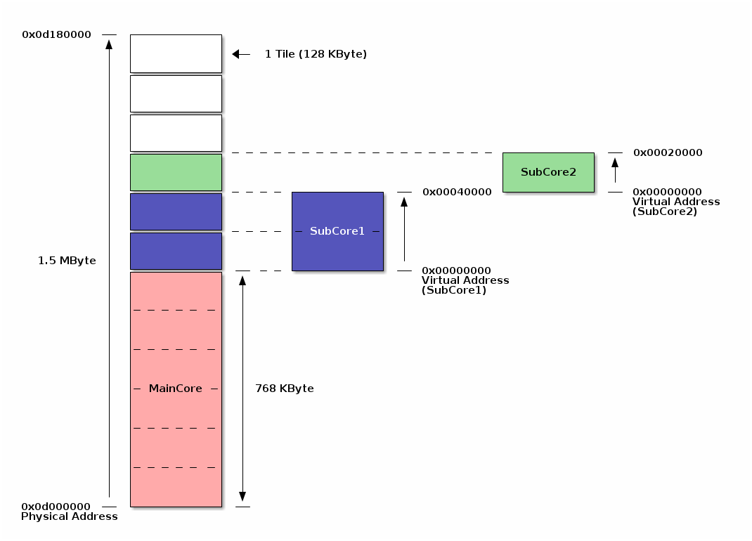
The application SRAM is divided into memory blocks called tiles in 128 KByte units.
In the default memory configuration, MainCore is allocated the first six tiles (768 KBytes) and the remaining six tiles (768 KBytes) are shared with SubCore, Audio DSP, and other libraries.
You can change the memory size allocated to MainCore from Arduino IDE menu.
| The memory size used by SubCore is automatically determined when you build a SubCore sketch. |
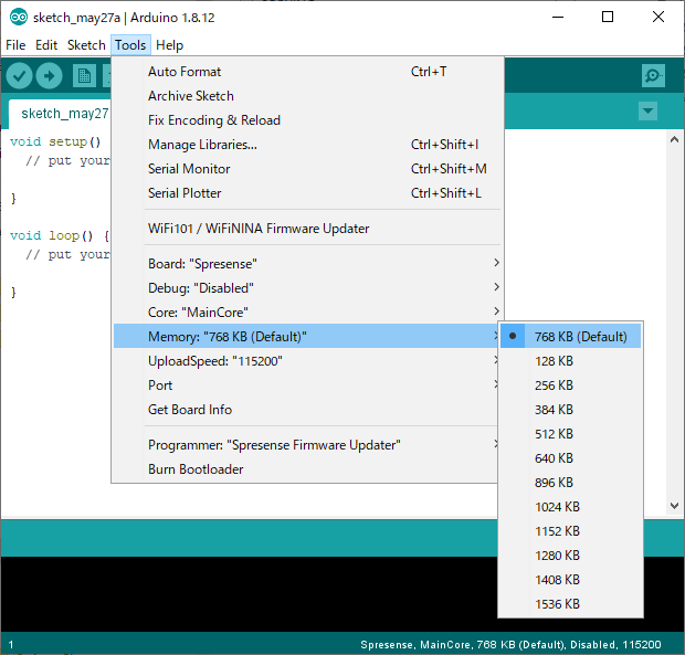
Maximum 1.5 MByte (1536 KB) of memory can be allocated to the user sketch in usecases without SubCore, Audio DSP. On the other hand, if you want to increase the memory size for SubCore and Audio DSP, you can reduce the size allocated to MainCore from 768 KB. Change the memory size according to the your usecase.
2. Spresense Arduino Libraries
2.1. Audio Library
Spresense audio library supports audio playback and audio recording, and uses SD card for file storage. This allows simple sketches to make use of the high resolution audio features.
Spresense has a high performance ADC and DAC with full digital amplifier which are controlled by the audio library.
The Spresense has six CPU cores. One of these is used as the application CPU which runs your sketch. The other five are called DSPs. The DSP cores perform audio signal processing, such as decoder and encoder. DSP binaries are provided here for easy and efficient audio application development.
|
The main features of the library are:
-
Audio recorder and capture
-
Audio player and renderer
-
Sound effector (for example, a bandpass filter for voice calls)
-
Sound sensing (for example, noise measurement, abnormal sound detection, etc.)
The features above support:
-
Volume control
-
Balance (L/R Gain)
-
Beep generation - Please note this produces a tone output to the headphone directly, unlike the Arduino tone() function which produces an output to one of the Arduino header pins.
The audio library allows selection of input and output channel.
Audio Input Channels are:
-
Analog microphone
-
Digital microphone
-
I2S
Audio Output Channel are:
-
Analog headphone
-
I2S
DSP codecs are available to support for multiple audio formats such as:
-
MP3
| If the MP3 file has ID3v2 TAG, the decoder will generate an error message and is not able to play the audio file. Please remove the tag information with tools such as MP3Tag if your MP3 file has large metadata such as image data. |
-
WAV (PCM)
Spresense can record and playback a range of sampling rates and bitrates when using compression.
For more detailed information see Audio Subsystem.
2.1.1. Pre-requisites for Audio
Please prepare these before using the audio library:
-
Spresense main board
-
Spresense extension board
-
Microphone for recording
-
Headphones for play back
-
MicroSD card
Spresense extension board has dedicated pins for audio and SD card, so all Arduino header pins remain available for other applications. For simple audio applications analog stereo input and output will be used.
-
Spresense extension board has a 3.5mm stereo headphone connector and a microphone interface.
For more detailed information on the pinout for the other audio connections please check How to use microphones, How to use speakers.
2.1.2. About layer structure
The stack diagram of the audio subsystem is shown below.
- High Level Interface
-
The highest layer, the layer can control at the highest level of abstraction. It controls while maintaining the integrity of the entire system.
The Arduino library uses only one class that
AudioClass.The functions that can be used are
-
Audio playback (rendering)
-
Audio recording (capture)
-
Microphone output (no signal processing)
-
Beep pronunciation
And so on.
-
- Object Level Interface
-
Functions block units (Objects) with a certain degree of abstraction such as Audio Recording Block and Audio Playback Block units are used as the API layer, and they connect in various patterns, an interface that allows the development of applications with highe flexibilities.
Detailed signal processing, DSP processing, etc in each Object are consistented within the Object.
This makes it possible to realize functions that are not defined in the High Level Interface.
Each object is
-
Audio capture function (MicFrontEnd Object)
-
Recording function (Recorder Object)
-
Playback function (Player Object)
-
Audio rendering function (OutputMixer Object)
-
Microphone output with signal processing (MicFrontEnd & OutputMixer Object)
-
Recognizer function (Recognizer Object)
-
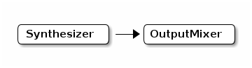
Synthesizer function (Synthesizer Object)
And so on.
-
- Low Level Interface (not supported)
-
Primitive signal processing block units (Components) such as voice decoding, encoding, and equalizing are used as the API layer, and they connect in various patterns, the interface provides that allows applications with very high flexibilities to be developed. However, the application must make adjustment of the each signal processings.
Currently, Low Level Interface is not supported.
2.1.3. DSP Codec Binary Installation
To use various Audio functions, it is necessary to install a binary called DSP that implements proprietary signal processing in SubCore. The procedure to install the binary file is as follows.
2.1.4. About High Level Interface
It will be the layer with the highest level of abstraction. It is easy to use, but its functions (operation mode) are limited.
Only one class object is used, AudioClass, and it can be used by defining it as below and creating an instance.
#include <Audio.h>

AudioClass *theAudio;
theAudio = AudioClass::getInstance();
This High Level Interface has the following state transitions.
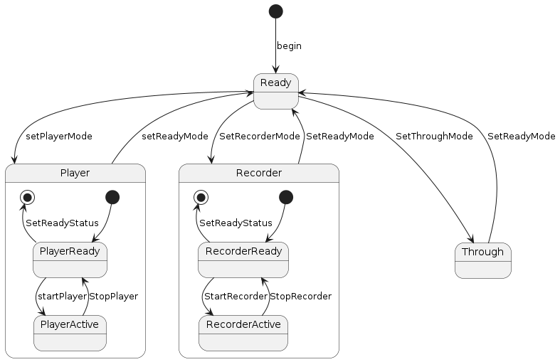
The explanation of each mode is as below.
-
Ready state
This is the state immediately after creating an object of the audio subsystem and starting it.
When not using audio, transitioning to this state will reduce the power consumption of the audio block to almost 0.
By setReadyMode the state can transite to the Ready state.
The state transition is as follows.
By setPlayerMode the state can transite to the Player state.
By setRecorderMode the state can transite to the Recorder state.
By setThroughMode the state can transite to the Through state.
-
Player status
It is a state to realize the function of decoding compressed audio files from SD cards and networks and pronouncing them to Analog Out and I2S.
There are two sub-states in the state, PlayerReady state and PlayerActive state.
PlayerReady state is the state in which music playback is stopped. Doxygen:startPlayer[] transitions to PlayerActive state and plays music.
The PlayerActive state is the state during music playback.
stopPlayer transitions to PlayerReady state and stops music playback.
You can have two instances of Player.
These instances has each sub-state of Player independently.
By setReadyMode the state can transite to the Ready state.
-
Recorder state
It is a state that realizes the function of compressing the audio data input from Mic and writing it to storage such as SD card, or upload it to a network such as WiFi/LTE and recording it.
There are two sub-states in the state, RecorderReady state and RecorderActive state.
RecorderReady state is the state where voice recording is stopped. Doxygen:startRecorder[] transitions to RecorderActive state and performs audio recording operation.
RecorderActive state is the state during audio recording.
stopRecorder transitions to RecorderReady state and stops audio recording.
setReadyMode only transitions to the Ready state.
By setReadyMode the state can transite to the Ready state.
-
Through state
It is a state that realizes the function to output the audio data input from (Analog/Digital) Mic to AnalogOut or I2S with very low power consumption and low delay without performing effect processing. This state has no sub-state.
By setReadyMode the state can transite to the Ready state.
2.1.5. About Object Level Interface
In the case of High Level Interface, the operation mode is decided to some extent. If this mode alone does not provide the desired functionality, you may be able to achieve the desired functionality by using the Object Level Interface and combining Objects to configure the system.
When using this Object Level Interface, it is necessary to include and instantiate the class object for each object.
The outline of each object is as below.
-
Audio capture function (MicFrontEnd Object)
This object captures audio input from the microphone. The captured audio can be passed to other objects.
#include <Frontend.h>

FrontEnd    *theFrontEnd;
theFrontEnd = FrontEnd::getInstance();
The captured audio data is sent to the RecorderObject for encoding, and also sent to the RecognizerObject for voice recognition.
In addition, by sending it to OutputMixerObjcet and pronouncing it as it is, it is possible to pronounce the signal processed sound with less delay from the input.
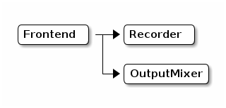
-
Recording function (Recorder Object)
Audio PCM data can be encoded and the resulting data can be obtained via SimpleFIFO or others.
#include <MediaRecorder.h>

MediaRecorder *theRecorder;
theRecorder = MediaRecorder::getInstance();-
Playback function (Player Object)
The audio stream data supplied via SimpleFIFO can be decoded and can rendering to output device.The result can be obtained by the callback function.
#include <MediaPlayer.h>

MediaPlayer *thePlayer;
thePlayer = MediaPlayer::getInstance();
The decoded PCM data can pronounce it by sending to OutputMixerObjcet.
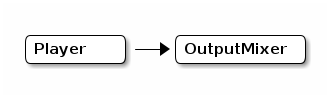
-
Rendering function (OutputMixer Object)
It renderings the received audio data.
#include <OutputMixer.h>

OutputMixer *theMixer;
theMixer = OutputMixer::getInstance();-
Recognizer Object (not supported)
It performs sound recognition of the received audio data.
-
Synthesizer Object (not supported)
It generates audio data based on the specified parameters.
The generated audio data can be pronounced by sending it to the OutputMixerObject .
2.1.5.1. Examples of each combined objects and functions
See the sample for each Object Level Interface and its Tutorial.
2.1.5.2. About the API of Object Level Interface
For details of each API, refer to the API reference.
2.1.5.3. About the examples using Object Level Interface
The examples using this Object Level Interface is as follows.
-
dual_players_objif
-
pcm_capture_objif
-
player_objIf
-
recorder_objif
-
recorder_wav_objif
-
recorder_with_rendering
See the tutorial for more information in the form of result data for each error notification.
2.1.6. Important point of various operations
Here are some notes about each operation.
2.1.6.1. Audio frequency constraints
The Audio function of Spresense can select only 48kHz sampling or 192kHz sampling for input/output audio data from HW due to HW restrictions.Therefore, the internal processing will be performed with 48kHz sampling or 192kHz sampling unless resampling with SW is performed.
2.1.6.2. Constraints on audio capture size and PCM data read
The audio capture operation by FrontEnd Object of Spresense has a maximum frame size of 1024 samples due to HW constraints. Also, from the viewpoint of real-time processing, the minimum number of samples is 240 samples. Therefore, the frame size that can be specified with the init function is 240 to 1024.
Also, due to the above restrictions, the frame size of the audio capture operation and WAV recording operation is 768 samples in the Audio class in the High Level Interface and the MediaRecorder Object & FrontEnd Object in the Object Level Interface.
readFrames does not depend on the size of the buffer, and if there is readable data, it reads for that size. So, if you want to read the data to fill the buffer, repeat readFrames until you write the rest, or wait long enough for the data to complete.
When resampling with SRC(Sampling Rate Converter), the frame size to be read changes depending on the multiple ratio. Please refer to the following.
| Samplingrate | Max samples |
|---|---|
16kHz |
341 |
48kHz |
1024 |
192kHz |
1024 |
2.1.7. DSP codec files
It is important that the DSP codec binary files can be accessed from the sketch when using the Audio library. The player and recorder examples put these files on the SD Card and use the location /mnt/sd0/BIN/ in initPlayer() or initRecorder() .
It is also possible to store the codec binary files in the SPI Flash memory on the main board using the DSP installer sketches described below. This uses the location /mnt/spif/BIN/ in initPlayer() or initRecorder(). If you install the DSP codec binary files to the SPI Flash memory, you will need to modify the example sketches accordingly.
| DSP file name | installer sketch | Description |
|---|---|---|
mp3_dec_installer |
Used for MP3 audio playback |
|
wav_dec_installer |
Used for WAV (PCM) audio playback |
|
mp3_enc_installer |
Used for MP3 audio recording |
|
src_installer |
Used for PCM audio recording |
The DSP can be installed onto the SD card or on the flash. There are two ways to install the DSP binary:
-
Copy into the SD card using a PC
-
Use the DSP installer sketch.
| It is only necessary to install the DSP binary once. There is no need to reinstall, as long as the files are not overwritten, deleted or the SDK is not updated. |
-
In case of copying the DSP codec binary files to the SD card:
Download the DSP file by clicking the DSP file name in the DSP binaries table. Please make a sub directory /BIN and copy the DSP binary file into the SD card /BIN folder.
In the audio player or recorder application program, it is necessary to specify the DSP installation location of the initPlayer() function or initRecorder() function. When you use the SD card, please specify /mnt/sd0/BIN . In the examples of audio applications, /mnt/sd0/BIN is used.
-
In case of using the DSP installer.
The DSP installer is launched from Arduino IDE, to open it click on the toolbar menu:
File → Examples → Examples for Spresense Audio → dsp_installer. There are different DSP installers available underdsp_installerfolder, one for each DSP as shown in the table above. Use DSP binaries table and select the appropriate DSP installer for your design. Figure 2. Launch DSP Installer
Please open the
Serial Monitor, after the sketch is done with compiling and uploading. Make sure you select the baudrate and specify where to install the DSP binary file. Follow the steps below:-
Open the Serial Monitor
-
Select the Baudrate: For this example the baudrate is 115200
-
Select where to install the binary file: Input [1] for SD Card or [2] for SPI-Flash. If you want to install to the SD card ( option[1] ), please insert the FAT-formatted SD card into the SD card slot on the Spresense extension board.
-
Click on Send button
 Figure 3. Select the installation directory
If the installation is successful, you will see this message on the Serial Monitor, as shown in the picture below.
 Figure 4. Execute the installation
-


Please note that, the audio application calls the initPlayer() or initRecorder() function with the argument of the DSP installation directory. If you installed DSP binary to the SD card, you have to specify the /mnt/sd0/BIN . If you installed into the SPI Flash, you have to specify the /mnt/spif/BIN . In the examples of audio applications, /mnt/sd0/BIN is used.
2.1.8. Errors and its handling in the Audio libraries
There are two types of errors that occur in the Audio libraries: errors that occur from inside the SDK and errors that occur from the Arduino library.
2.1.8.1. Errors from the Arduino library
| Error Code | Value | Description |
|---|---|---|
AUDIOLIB_ECODE_OK |
0 |
Normal termination |
AUDIOLIB_ECODE_SHARED_MEMORY_ERROR |
1 |
Shared Memory allocation error |
AUDIOLIB_ECODE_SIMPLEFIFO_ERROR |
2 |
Simple FIFO error |
AUDIOLIB_ECODE_AUDIOCOMMAND_ERROR |
3 |
API execution error |
AUDIOLIB_ECODE_FILEACCESS_ERROR |
4 |
File access error |
AUDIOLIB_ECODE_FILEEND |
5 |
End-of-file error |
AUDIOLIB_ECODE_BUFFER_AREA_ERROR |
6 |
Buffer area undefined error |
AUDIOLIB_ECODE_BUFFER_SIZE_ERROR |
7 |
Buffer size specification error |
AUDIOLIB_ECODE_INSUFFICIENT_BUFFER_AREA |
8 |
Buffer area shortage error |
AUDIOLIB_ECODE_WAV_PARSE_ERROR |
9 |
Unused |
AUDIOLIB_ECODE_PARAMETER_ERROR |
10 |
Parameter error |
| Error Code | Value | Description |
|---|---|---|
FRONTEND_ECODE_OK |
0 |
Normal termination |
FRONTEND_ECODE_COMMAND_ERROR |
1 |
API execution error |
FRONTEND_ECODE_BASEBAND_ERROR |
2 |
AudioDriver error |
| Error Code | Value | Description |
|---|---|---|
MEDIARECORDER_ECODE_OK |
0 |
Normal termination |
MEDIARECORDER_ECODE_COMMAND_ERROR |
1 |
API execution error |
MEDIARECORDER_ECODE_BUFFER_INIT_ERROR |
2 |
Buffer initialization error |
MEDIARECORDER_ECODE_BUFFER_POLL_ERROR |
3 |
Buffer polling error |
MEDIARECORDER_ECODE_DSP_ACCESS_ERROR |
4 |
DSP Binary File Access Error |
MEDIARECORDER_ECODE_FILEACCESS_ERROR |
5 |
File access error |
MEDIARECORDER_ECODE_BUFFER_SIZE_ERROR |
6 |
Buffer size specification error |
MEDIARECORDER_ECODE_BUFFER_AREA_ERROR |
7 |
Buffer area undefined error |
MEDIARECORDER_ECODE_INSUFFICIENT_BUFFER_AREA |
8 |
Insufficient buffer space error |
MEDIARECORDER_ECODE_BASEBAND_ERROR |
9 |
Unused |
MEDIARECORDER_ECODE_BUFFER_ALLOC_ERROR |
10 |
Buffer area allocation error |
| Error Code | Value | Description |
|---|---|---|
MEDIAPLAYER_ECODE_OK |
0 |
Normal termination |
MEDIAPLAYER_ECODE_COMMAND_ERROR |
1 |
API execution error |
MEDIAPLAYER_ECODE_SIMPLEFIFO_ERROR |
2 |
|
MEDIAPLAYER_ECODE_FILEACCESS_ERROR |
3 |
File access error |
MEDIAPLAYER_ECODE_FILEEND |
4 |
File termination error |
MEDIAPLAYER_ECODE_SHARED_MEMORY_ERROR |
5 |
Unused |
MEDIAPLAYER_ECODE_WAV_PARSER_ERROR |
6 |
Unused |
MEDIAPLAYER_ECODE_BUFFERSIZE_ERROR |
7 |
Buffer size specification error |
MEDIAPLAYER_ECODE_BUFFERALLOC_ERROR |
8 |
Buffer area allocation error |
| Error Code | Value | Description |
|---|---|---|
OUTPUTMIXER_ECODE_OK |
0 |
Normal termination |
OUTPUTMIXER_ECODE_COMMAND_ERROR |
1 |
API execution error |
2.1.8.2. Errors from SDK
Errors that occur inside the SDK are notified to the callback function registered with begin in the form of error notification result data.
Errors include [_Response Error] that occurs when there is a problem with the executed API and [_Attention Error] that occurs when an error is detected by internal processing.
In case of response error and attention error occurs, please add error handling and take corrective action according to each error.
2.1.9. Response Error
If the API executed in the Audio library controls different from the specifications such as status violation or parameter error, Response Error will occur and the error content will be call back with the parameter.
For the data format of Response Error,
See Result Format and ErrorResponse.
"ErrorResponse" has "Error Code", and "Error Code" makes it possible to know what caused the error.
Below is a list of "Error Codes".
| Error Code | Value | Description |
|---|---|---|
0x01 |
State violation |
|
0x02 |
Packet length mismatch |
|
0x03 |
Unknown command |
|
0x04 |
Invalid command |
|
0x05 |
Power ON failure |
|
0x06 |
Power OFF failure |
|
0x07 |
DSP startup failure |
|
0x08 |
DSP termination failure |
|
0x09 |
DSP version mismatch |
|
0x0A |
Input/output parameter error |
|
0x0B |
Data path clear failure |
|
0x0C |
Input/output is disabled |
|
0x0D |
Decoder DSP initialization failure |
|
0x0E |
Encoder DSP initialization failed |
|
0x0F |
Filter DSP initialization failed |
|
0x11 |
Incorrect codec type specification |
|
0x13 |
Wrong number of channels specified |
|
0x14 |
Incorrect sampling frequency |
|
0x15 |
Incorrect bit rate specification |
|
0x16 |
Incorrect bit length specification |
|
0x17 |
Incorrect compression ratio specification |
|
0x18 |
Incorrect specification of Player instance |
|
0x19 |
Incorrect input device specification |
|
0x1A |
Incorrect output device specification |
|
0x1B |
Incorrect input device handle specification |
|
0x28 |
Incorrect mute parameter specification |
|
0x2B |
I/O function initialization failure |
|
0x2C |
Input data acquisition failure |
|
0x2E |
Memory pool setting failure |
|
0x2F |
Simple FIFO data is exhausted |
|
0x30 |
Incorrect microphone gain specification |
|
0x32 |
Incorrect output destination setting |
|
0x33 |
Incorrect clear stereo setting |
|
0x34 |
Incorrect volume specification |
|
0x35 |
Incorrect mute target specification |
|
0x36 |
Incorrect beep parameter specification |
|
0x37 |
Data queue management failure |
|
0x39 |
Incorrect clock operation mode specification |
|
0x3A |
Clock operation mode setting failure |
|
0x3B |
Incorrect speaker drive capability setting |
|
0x3D |
Incorrect microphone setting |
|
0x3E |
Used without generating the Object layer module |
See here for more information on "Error Code".
2.1.10. Attention error
If any error is detected during processing (not command processing) inside the Audio SubSystem in SDK, a notification event will be send.
See ErrorAttention for the data format of Attention Error.
Attention Errors includes the system errors like flow control errors such as ES (Elementary Stream) supply error (underflow) during playback operation and ES write buffer overflow (overflow) during recording operation, memory resource exhaustion, and real-time process delay. And they includes fatal errors from HW and other that require a system reset to be recovered.
These errors can be determined by the "Attention Code" included "Error Attention".
Please make corrections based on "Attention Code". Also, changing the implementation method may improve the error.
Below is a list of "Attention Codes" that are included "ErrorAttention".
| Attention Code | Value | Description |
|---|---|---|
0x01 |
DMA transfer underflow |
|
0x02 |
DMA transfer overflow |
|
0x03 |
DMA transfer failure |
|
0x05 |
Underflow of SimpleFIFO |
|
0x06 |
Overflow of SimpleFIFO |
|
0x07 |
Illegal event reception |
|
0x08 |
Internal status error |
|
0x09 |
Internal parameter error |
|
0x0A |
Pop error for internal queue |
|
0x0B |
Push error for internal queue |
|
0x0C |
Internal queue exhaustion |
|
0x0D |
Memory handle acquisition failure |
|
0x0E |
Memory handle release failure |
|
0x0F |
Task creation failure |
|
0x10 |
Failure to create or delete an instance |
|
0x12 |
DSP startup failure |
|
0x13 |
DSP termination failure |
|
0x14 |
Error in DSP processing |
|
0x16 |
Invalid data received from DSP |
|
0x18 |
DSP version mismatch |
|
0x19 |
Error in audio driver |
|
0x1A |
ES data analysis error |
|
0x1E |
Acquisition failure of DSP log buffer |
|
0x1F |
Fatal error in DSP processing |
|
0x20 |
Command transmission error to DSP |
Please refer to here for details of "Attention Code".
A level of importance is specified for the attention notification, and the processing method for recovery is dependent on the severity of the error.
| Level | value | Description |
|---|---|---|
FATAL |
0x03 |
A system call error, etc. that is not recoverable and requires a reset to restore. |
ERROR |
0x02 |
It is an error in the operation of which the audio system can not continued with the internal error (queue Full / Empty, DSP load / unload etc). It is possible to recover by returning the system to the initial state (Ready state). |
WARN |
0x01 |
There is a possibility that the operation is abnormal, such as encode / decode error, data underflow / overflow, etc. There is a possibility that abnormality has occurred in voice data, etc., but operation can continue. |
2.1.11. Error Code List
Below is a list of "Error Code" added to "Error Response".
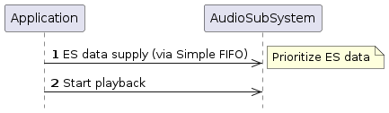
2.1.11.32. AS_ECODE_SIMPLE_FIFO_UNDERFLOW
- code
-
0x2F
- description
-
At the start of Audio playback, the Simple FIFO used as the ES buffer underflows.
When starting playback, AudioSubSystem immediately extracts ES data from SimpleFIFO and starts decoding. So in the application, it is necessary to put ES data in the FIFO before playback starts.
2.1.13. Module ID List
AudioSubSystem ID list of modules to be used internally.
It is notified with Attention callback along with attention code, and it judges which module caused an error.
| Module ID | Value | Description |
|---|---|---|
AS_MODULE_ID_AUDIO_MANAGER |
0 |
Audio Manager |
AS_MODULE_ID_AUDIO_DRIVER |
1 |
Audio Baseband Driver |
AS_MODULE_ID_MIC_FRONTEND_OBJ |
2 |
FrontEnd Object |
AS_MODULE_ID_INPUT_DATA_MNG_OBJ |
3 |
Input Data Manager Object |
AS_MODULE_ID_MEDIA_RECORDER_OBJ |
4 |
Media Recorder Object |
AS_MODULE_ID_OUTPUT_MIX_OBJ |
5 |
Output Mix Object |
AS_MODULE_ID_PLAYER_OBJ |
6 |
Player Object |
AS_MODULE_ID_RECOGNITION_OBJ |
7 |
Recognition Object |
AS_MODULE_ID_SOUND_EFFECT_OBJ |
8 |
Sound Effect Object |
AS_MODULE_ID_SYNTHESIZER_OBJ |
9 |
Synthesizer Object |
AS_MODULE_ID_CAPTURE_CMP |
10 |
Capture Component |
AS_MODULE_ID_DECODER_CMP |
11 |
Decoder Component |
AS_MODULE_ID_ENCODER_CMP |
12 |
Encoder Component |
AS_MODULE_ID_FILTER_CMP |
13 |
Filter Component |
AS_MODULE_ID_RECOGNITION_CMP |
14 |
Recognition Component |
AS_MODULE_ID_RENDERER_CMP |
15 |
Renderer Component |
AS_MODULE_ID_POSTPROC_CMP |
16 |
Postfilter Component |
AS_MODULE_ID_OSCILLATOR_CMP |
17 |
Oscillator Component |
AS_MODULE_ID_CUSTOM_CMP |
18 |
Custom Component |
2.2. Camera Library
This section explains how to use Camera library of Spresense Arduino Library.
2.2.1. Overview
The Spresense camera library overview is shown as below:
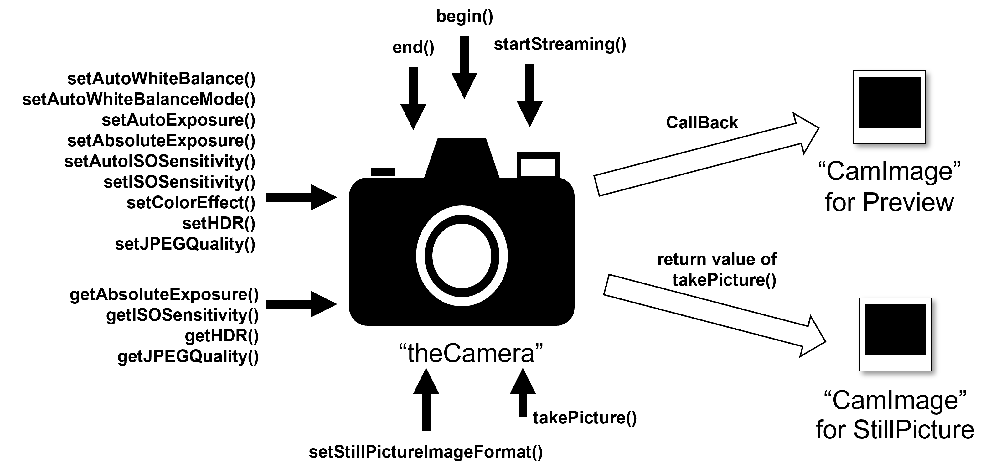
In Spresense Arduino Library Camera, there are two classes.
One is "theCamera" which is an instance of CameraClass, and the other is CamImage class which is manipulate image from theCamera.
"theCamera" has three major functions:
-
Video Stream function to get Camera preview image
-
Setting function to set camera parameters
-
Capture picture function to get high-resolution JPEG image.
CamImage class is for manipulating an image. The below figure is the overview of the CamImage.
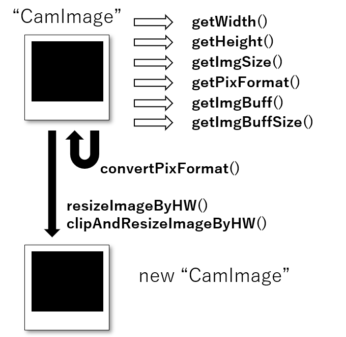
CamImage class has two major functions:
-
To get information of an image from theCamera class
-
To convert image
Please find the description of supported functions in the next sections.
2.2.2. Video Stream function to get Camera preview image
The viewfinder of a camera shows real-time images shown on a camera.
This real-time image (real-time movie) is called Preview image. "theCamera" has a function to acquire this Preview image frame by frame.
To obtain the Preview image, first determine the image format of the Preview image using the begin() method function. The definition of the begin() method function is as follows.
begin(
    int buff_num=1,
    CAM_VIDEO_FPS fps = CAM_VIDEO_FPS_30,
    int video_width   = CAM_IMGSIZE_QVGA_H,
    int video_height  = CAM_IMGSIZE_QVGA_V,
    CAM_IMAGE_PIX_FMT fmt=CAM_IMAGE_PIX_FMT_YUV422,
    int jpgbufsize_divisor = 7)
All the parameters given to begin() method function determine the parameters of the Preview image. The parameters and the default values are as follow : Number of preview image buffers inside theCamera = 1 Vertical and horizontal size of the image = QVGA (320 x 240) Frame rate of Video (how many frames to acquire per second) = 30 FPS (30 images per second) Image data pixel format = YUV 422
As for the number of internal image buffers, it would be sufficient if you use the default value of 1.
In cases you need to do heavy processing, for example when you are processing large number of images. You need to increase the number of image buffers to be able to do parallel image processing and image acquisition. In such case, by setting the number of internal image buffers to 2, you can perform parallel image processing from the camera while the image frame rate is improved in some cases as a result. This process will consume about 150 KB of buffer memory with QVGA, so please be careful when setting a large number of sheets.
|
The supported pixel formats for the preview image are YUV422, RGB565 and JPEG. The available frame sizes and frame intervals are the same as SDK. Please refer to Settings available in ISX012 or Settings available in ISX019 |
The begin() method function is the first function to call when using theCamera. When the begin() method function is completed successfully, register the callback function to obtain the Preview image using the startStreaming() method function. The callback function is as follows:
void camera_callback(CamImage img)The user implements its own function of this type and registers it by using the startStreaming() method function. When "true" is specified as the first argument of startStreaming(), acquisition of the video image for Preview is started, and the registered callback function is called each time the image is acquired. The frequency of acquiring images is determined by the frame rate specified by the begin() method function. The callback function of the next frame will not be called unless the callback function implemented by the user is terminated. To stop the acquisition of the Preview image, call the startStreaming() method function with the first argument of the startStreaming() method function set to false.
2.2.3. Setting function to set Camera parameters
Spresense Camera, the same as any other camera, can set various settings such as color adjustment and brightness.
| Method name | Description |
|---|---|
Start and stop automatic white balance of Camera |
|
Mode setting at automatic white balance |
|
Start and stop automatic exposure of Camera |
|
Set camera exposure time in 100 microseconds unit |
|
Start and stop automatic ISO sensitivity of Camera |
|
Set ISO sensitivity setting with manual ISO sensitivity setting |
|
Set image effect |
|
Set HDR mode |
|
Set JPEG quality |
There are also parameters that can get the current value using the following APIs.
| Method name | Description |
|---|---|
Get camera exposure time in 100 microseconds unit |
|
Get camera ISO sensitivity |
|
Get HDR mode |
|
Get JPEG quality |
These method functions can be called at any time after calling the begin() method function.
2.2.4. Capture picture function to get high-resolution JPEG image.
Preview images are low resolution, you can get images with frequency of frame rate as movies. On the other hand, when acquiring data as a photograph, the Spresense Camera can acquire high-resolution JPEG compressed images.
First of all, we will process "to set the film" on theCamera. The method function that does this is setStillPictureImageFormat(). Use this method function to set the image size and pixel format for still images (photographs).
setStillPictureImageFormat(
    int width,
    int height,
    CAM_IMAGE_PIX_FMT fmt = CAM_IMAGE_PIX_FMT_JPEG,
    int jpgbufsize_divisor = 7)
Specify the horizontal and vertical size of the image with the first and second arguments. The third argument specifies the pixel format of the image.
|
If the setStillPictureImageFormat () method function is set once, the setting is permanently effective unless the parameter is changed. The supported pixel formats are YUV422, RGB565 and JPEG. The available frame sizes and frame intervals are the same as SDK. Please refer to Settings available in ISX012 or Settings available in ISX019 |
After setting the image, at the arbitrary timing, do "push the shutter" process and get the photo data. The method function for that will be takePicture(), which returns an instance of CamImage as a return value. If an error occurs during photography, it returns an empty CamImage. To determine whether an instance of CamImage is empty, you can check it with isAvailable() of CamImage class.
|
If the acquisition of CamImage fails in JPEG cases,
it is possible that the capacity of the JPEG buffer size set by |
2.2.5. To get informations of an Image from theCamera
The CamImage instance, obtained by callback with startStreaming() or by the return value of takePicture(), contains information on the acquired image. Image information can be obtained using the method function of the CamImage class.
| Method name | Description |
|---|---|
Check availability of this CamImage instance |
|
Get image width in pixels |
|
Get height of image in pixels |
|
Get pixel format of image |
|
Get size of image data in bytes |
|
Get buffer address of image data |
|
Get image buffer size in bytes |
2.2.6. To convert image
CamImage instances have one image transformation method function.
| Method name | Description |
|---|---|
Convert the image from the current pixel format to another pixel format |
|
Resize image |
|
Clip and resize image |
When you want images to appear on the display, the display’s pixel format is RGB format usually. If your pixel format is different than RGB, use the convertPixFormat() method function to convert pixel format of your image to RGB.
convertPixFormat() converts its own pixel format and overwrites own image data.
|
Currently, there are the following restrictions. - convertPixformat() supports only two conversion one is from YUV422 to RGB and the other is YUV422 to GRAY. - About the resize ratio of resizeImageByHW() and clipAndResizeImageByHWi, support only power of 2(from 2^(-6) to 2^(6)). |
2.2.7. Explanation by sample code
This section explains how to use the Spresense camera, using the sample code of Camera included in the Spresense Arduino Package.
You can open the sample code from Arduino IDE’s menu bar.
"File" ⇒ "Sketch example" ⇒ "Camera in Spresense sketch example" ⇒ "camera"
/*
 *  camera.ino - Simple camera example sketch
 *  Copyright 2018, 2022 Sony Semiconductor Solutions Corporation
 *
 *  This library is free software; you can redistribute it and/or
 *  modify it under the terms of the GNU Lesser General Public
 *  License as published by the Free Software Foundation; either
 *  version 2.1 of the License, or (at your option) any later version.
 *
 *  This library is distributed in the hope that it will be useful,
 *  but WITHOUT ANY WARRANTY; without even the implied warranty of
 *  MERCHANTABILITY or FITNESS FOR A PARTICULAR PURPOSE.  See the GNU
 *  Lesser General Public License for more details.
 *
 *  You should have received a copy of the GNU Lesser General Public
 *  License along with this library; if not, write to the Free Software
 *  Foundation, Inc., 51 Franklin St, Fifth Floor, Boston, MA  02110-1301  USA
 *
 *  This is a test app for the camera library.
 *  This library can only be used on the Spresense with the FCBGA chip package.
 */

#include <SDHCI.h>
#include <stdio.h>  /* for sprintf */

#include <Camera.h>

#define BAUDRATE                (115200)
#define TOTAL_PICTURE_COUNT     (10)

SDClass  theSD;
int take_picture_count = 0;

/**
 * Print error message
 */

void printError(enum CamErr err)
{
  Serial.print("Error: ");
  switch (err)
    {
      case CAM_ERR_NO_DEVICE:
        Serial.println("No Device");
        break;
      case CAM_ERR_ILLEGAL_DEVERR:
        Serial.println("Illegal device error");
        break;
      case CAM_ERR_ALREADY_INITIALIZED:
        Serial.println("Already initialized");
        break;
      case CAM_ERR_NOT_INITIALIZED:
        Serial.println("Not initialized");
        break;
      case CAM_ERR_NOT_STILL_INITIALIZED:
        Serial.println("Still picture not initialized");
        break;
      case CAM_ERR_CANT_CREATE_THREAD:
        Serial.println("Failed to create thread");
        break;
      case CAM_ERR_INVALID_PARAM:
        Serial.println("Invalid parameter");
        break;
      case CAM_ERR_NO_MEMORY:
        Serial.println("No memory");
        break;
      case CAM_ERR_USR_INUSED:
        Serial.println("Buffer already in use");
        break;
      case CAM_ERR_NOT_PERMITTED:
        Serial.println("Operation not permitted");
        break;
      default:
        break;
    }
}

/**
 * Callback from Camera library when video frame is captured.
 */

void CamCB(CamImage img)
{

  /* Check the img instance is available or not. */

  if (img.isAvailable())
    {

      /* If you want RGB565 data, convert image data format to RGB565 */

      img.convertPixFormat(CAM_IMAGE_PIX_FMT_RGB565);

      /* You can use image data directly by using getImgSize() and getImgBuff().
       * for displaying image to a display, etc. */

      Serial.print("Image data size = ");
      Serial.print(img.getImgSize(), DEC);
      Serial.print(" , ");

      Serial.print("buff addr = ");
      Serial.print((unsigned long)img.getImgBuff(), HEX);
      Serial.println("");
    }
  else
    {
      Serial.println("Failed to get video stream image");
    }
}

/**
 * @brief Initialize camera
 */
void setup()
{
  CamErr err;

  /* Open serial communications and wait for port to open */

  Serial.begin(BAUDRATE);
  while (!Serial)
    {
      ; /* wait for serial port to connect. Needed for native USB port only */
    }

  /* Initialize SD */
  while (!theSD.begin())
    {
      /* wait until SD card is mounted. */
      Serial.println("Insert SD card.");
    }

  /* begin() without parameters means that
   * number of buffers = 1, 30FPS, QVGA, YUV 4:2:2 format */

  Serial.println("Prepare camera");
  err = theCamera.begin();
  if (err != CAM_ERR_SUCCESS)
    {
      printError(err);
    }

  /* Start video stream.
   * If received video stream data from camera device,
   *  camera library call CamCB.
   */

  Serial.println("Start streaming");
  err = theCamera.startStreaming(true, CamCB);
  if (err != CAM_ERR_SUCCESS)
    {
      printError(err);
    }

  /* Auto white balance configuration */

  Serial.println("Set Auto white balance parameter");
  err = theCamera.setAutoWhiteBalanceMode(CAM_WHITE_BALANCE_DAYLIGHT);
  if (err != CAM_ERR_SUCCESS)
    {
      printError(err);
    }

  /* Set parameters about still picture.
   * In the following case, QUADVGA and JPEG.
   */

  Serial.println("Set still picture format");
  err = theCamera.setStillPictureImageFormat(
     CAM_IMGSIZE_QUADVGA_H,
     CAM_IMGSIZE_QUADVGA_V,
     CAM_IMAGE_PIX_FMT_JPG);
  if (err != CAM_ERR_SUCCESS)
    {
      printError(err);
    }
}

/**
 * @brief Take picture with format JPEG per second
 */

void loop()
{
  sleep(1); /* wait for one second to take still picture. */

  /* You can change the format of still picture at here also, if you want. */

  /* theCamera.setStillPictureImageFormat(
   *   CAM_IMGSIZE_HD_H,
   *   CAM_IMGSIZE_HD_V,
   *   CAM_IMAGE_PIX_FMT_JPG);
   */

  /* This sample code can take pictures in every one second from starting. */

  if (take_picture_count < TOTAL_PICTURE_COUNT)
    {

      /* Take still picture.
      * Unlike video stream(startStreaming) , this API wait to receive image data
      *  from camera device.
      */

      Serial.println("call takePicture()");
      CamImage img = theCamera.takePicture();

      /* Check availability of the img instance. */
      /* If any errors occur, the img is not available. */

      if (img.isAvailable())
        {
          /* Create file name */

          char filename[16] = {0};
          sprintf(filename, "PICT%03d.JPG", take_picture_count);

          Serial.print("Save taken picture as ");
          Serial.print(filename);
          Serial.println("");

          /* Remove the old file with the same file name as new created file,
           * and create new file.
           */

          theSD.remove(filename);
          File myFile = theSD.open(filename, FILE_WRITE);
          myFile.write(img.getImgBuff(), img.getImgSize());
          myFile.close();
        }
      else
        {
          /* The size of a picture may exceed the allocated memory size.
           * Then, allocate the larger memory size and/or decrease the size of a picture.
           * [How to allocate the larger memory]
           * - Decrease jpgbufsize_divisor specified by setStillPictureImageFormat()
           * - Increase the Memory size from Arduino IDE tools Menu
           * [How to decrease the size of a picture]
           * - Decrease the JPEG quality by setJPEGQuality()
           */

          Serial.println("Failed to take picture");
        }
    }
  else if (take_picture_count == TOTAL_PICTURE_COUNT)
    {
      Serial.println("End.");
      theCamera.end();
    }

  take_picture_count++;
}
For this sample please do the setup as follow: - Set the Preview image to QVGA - Set the frame rate to 30 FPS, to acquire 30 frames of data - take a JPEG picture and save it to SDCard.
After doing the setup, please follow these steps: "initial setting", "error print", "setup()", "preview callback" and "loop()".
Please find the description of these steps here:
2.2.7.1. Initial setting
/*
 *  camera.ino - Simple camera example sketch
 *  Copyright 2018, 2022 Sony Semiconductor Solutions Corporation
 *
 *  This library is free software; you can redistribute it and/or
 *  modify it under the terms of the GNU Lesser General Public
 *  License as published by the Free Software Foundation; either
 *  version 2.1 of the License, or (at your option) any later version.
 *
 *  This library is distributed in the hope that it will be useful,
 *  but WITHOUT ANY WARRANTY; without even the implied warranty of
 *  MERCHANTABILITY or FITNESS FOR A PARTICULAR PURPOSE.  See the GNU
 *  Lesser General Public License for more details.
 *
 *  You should have received a copy of the GNU Lesser General Public
 *  License along with this library; if not, write to the Free Software
 *  Foundation, Inc., 51 Franklin St, Fifth Floor, Boston, MA  02110-1301  USA
 *
 *  This is a test app for the camera library.
 *  This library can only be used on the Spresense with the FCBGA chip package.
 */

#include <SDHCI.h>
#include <stdio.h>  /* for sprintf */

#include <Camera.h>

#define BAUDRATE                (115200)
#define TOTAL_PICTURE_COUNT     (10)

SDClass  theSD;
int take_picture_count = 0;
First, when using the Spresense camera library, you need to include the header file <Camera.h>.
#include <Camera.h>Including this header file makes it possible to use the theCamera instance.
After that, we define variables that are used in the loop() function.
int take_picture_count = 0;The take_picture_count, is a variable which is counting up every second when takePicture() is called. When you use this variable you can control the file name and maximum file number. (In this example, it stops taking picture when picture number is 10.)
2.2.7.2. error print
/**
 * Print error message
 */

void printError(enum CamErr err)
{
  Serial.print("Error: ");
  switch (err)
    {
      case CAM_ERR_NO_DEVICE:
        Serial.println("No Device");
        break;
      case CAM_ERR_ILLEGAL_DEVERR:
        Serial.println("Illegal device error");
        break;
      case CAM_ERR_ALREADY_INITIALIZED:
        Serial.println("Already initialized");
        break;
      case CAM_ERR_NOT_INITIALIZED:
        Serial.println("Not initialized");
        break;
      case CAM_ERR_NOT_STILL_INITIALIZED:
        Serial.println("Still picture not initialized");
        break;
      case CAM_ERR_CANT_CREATE_THREAD:
        Serial.println("Failed to create thread");
        break;
      case CAM_ERR_INVALID_PARAM:
        Serial.println("Invalid parameter");
        break;
      case CAM_ERR_NO_MEMORY:
        Serial.println("No memory");
        break;
      case CAM_ERR_USR_INUSED:
        Serial.println("Buffer already in use");
        break;
      case CAM_ERR_NOT_PERMITTED:
        Serial.println("Operation not permitted");
        break;
      default:
        break;
    }
}
Interpret the error code defined in Camera library and output the error content to serial monitor.
2.2.7.3. preview callback
/**
 * Callback from Camera library when video frame is captured.
 */

void CamCB(CamImage img)
{

  /* Check the img instance is available or not. */

  if (img.isAvailable())
    {

      /* If you want RGB565 data, convert image data format to RGB565 */

      img.convertPixFormat(CAM_IMAGE_PIX_FMT_RGB565);

      /* You can use image data directly by using getImgSize() and getImgBuff().
       * for displaying image to a display, etc. */

      Serial.print("Image data size = ");
      Serial.print(img.getImgSize(), DEC);
      Serial.print(" , ");

      Serial.print("buff addr = ");
      Serial.print((unsigned long)img.getImgBuff(), HEX);
      Serial.println("");
    }
  else
    {
      Serial.println("Failed to get video stream image");
    }
}
This function is registered on startStreaming() method and it will be called when the preview image is available. This function, check the availability of the CamImage instance at first, and then convert pixel format from YUV422 to RGB565. After the conversion, message of data size and memory address of the image will be sent via Serial. Generally, at this moment, add implementation that the image data will be displayed on a connected LCD monitor like a camera view finder.
2.2.7.4. setup()
/**
 * @brief Initialize camera
 */
void setup()
{
  CamErr err;

  /* Open serial communications and wait for port to open */

  Serial.begin(BAUDRATE);
  while (!Serial)
    {
      ; /* wait for serial port to connect. Needed for native USB port only */
    }

  /* Initialize SD */
  while (!theSD.begin())
    {
      /* wait until SD card is mounted. */
      Serial.println("Insert SD card.");
    }

  /* begin() without parameters means that
   * number of buffers = 1, 30FPS, QVGA, YUV 4:2:2 format */

  Serial.println("Prepare camera");
  err = theCamera.begin();
  if (err != CAM_ERR_SUCCESS)
    {
      printError(err);
    }

  /* Start video stream.
   * If received video stream data from camera device,
   *  camera library call CamCB.
   */

  Serial.println("Start streaming");
  err = theCamera.startStreaming(true, CamCB);
  if (err != CAM_ERR_SUCCESS)
    {
      printError(err);
    }

  /* Auto white balance configuration */

  Serial.println("Set Auto white balance parameter");
  err = theCamera.setAutoWhiteBalanceMode(CAM_WHITE_BALANCE_DAYLIGHT);
  if (err != CAM_ERR_SUCCESS)
    {
      printError(err);
    }

  /* Set parameters about still picture.
   * In the following case, QUADVGA and JPEG.
   */

  Serial.println("Set still picture format");
  err = theCamera.setStillPictureImageFormat(
     CAM_IMGSIZE_QUADVGA_H,
     CAM_IMGSIZE_QUADVGA_V,
     CAM_IMAGE_PIX_FMT_JPG);
  if (err != CAM_ERR_SUCCESS)
    {
      printError(err);
    }
}
The setup() initially sets up serial for message display, then calls Camera’s begin() method function. After that, it will enable preview callback function setting and callback with startStreaming(), and set auto white balance mode to day-light by calling setAutoWhiteBalanceMode(). Finally, with setStillPictureImageFormat(), setting for Quad HD size photograph is done.
2.2.7.5. loop()
/**
 * @brief Take picture with format JPEG per second
 */

void loop()
{
  sleep(1); /* wait for one second to take still picture. */

  /* You can change the format of still picture at here also, if you want. */

  /* theCamera.setStillPictureImageFormat(
   *   CAM_IMGSIZE_HD_H,
   *   CAM_IMGSIZE_HD_V,
   *   CAM_IMAGE_PIX_FMT_JPG);
   */

  /* This sample code can take pictures in every one second from starting. */

  if (take_picture_count < TOTAL_PICTURE_COUNT)
    {

      /* Take still picture.
      * Unlike video stream(startStreaming) , this API wait to receive image data
      *  from camera device.
      */

      Serial.println("call takePicture()");
      CamImage img = theCamera.takePicture();

      /* Check availability of the img instance. */
      /* If any errors occur, the img is not available. */

      if (img.isAvailable())
        {
          /* Create file name */

          char filename[16] = {0};
          sprintf(filename, "PICT%03d.JPG", take_picture_count);

          Serial.print("Save taken picture as ");
          Serial.print(filename);
          Serial.println("");

          /* Remove the old file with the same file name as new created file,
           * and create new file.
           */

          theSD.remove(filename);
          File myFile = theSD.open(filename, FILE_WRITE);
          myFile.write(img.getImgBuff(), img.getImgSize());
          myFile.close();
        }
      else
        {
          /* The size of a picture may exceed the allocated memory size.
           * Then, allocate the larger memory size and/or decrease the size of a picture.
           * [How to allocate the larger memory]
           * - Decrease jpgbufsize_divisor specified by setStillPictureImageFormat()
           * - Increase the Memory size from Arduino IDE tools Menu
           * [How to decrease the size of a picture]
           * - Decrease the JPEG quality by setJPEGQuality()
           */

          Serial.println("Failed to take picture");
        }
    }
  else if (take_picture_count == TOTAL_PICTURE_COUNT)
    {
      Serial.println("End.");
      theCamera.end();
    }

  take_picture_count++;
}
In the loop() function, wait for 1 second by using sleep() function at the beginning. After 1 second, it checks whether the value of the take_picture_count variable exceeds 10. If it does not exceed 10, it enters the photo shooting process. In the shooting process, the takePicture() method function is called, take a picture and assign the obtained picture to the img variable. Then check that if the img variable is available with the isAvailable() function, and save the acquired image to the SD card. Finally, take_picture_count is incremented (by 1) and the loop() function is terminated. When the value of the take_picture_count variable is 10, end() methods of Camera is called and the Camera library procedure finishes.
The explanation for using the sample finished here. Let’s create an original camera device using the Spresense camera.
2.3. DNNRT Library
The DNN Runtime library can perform recognition processing using the Deep Neural Network (DNN) using trained models by Neural Network Libraries or Neural Network Console provided by Sony.
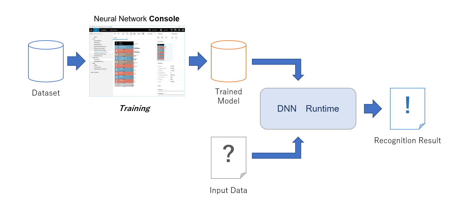
DNNRT library has 2 parts. One is DNNRT as a core library, and second is DNNVariable which is for using data I/O.
This section explains how to use DNNRT for recognizing handwritten characters from 0 to 9 (number_recognition.ino) as an example.
2.3.1. Preparation of a trained model
To use the DNNRT, first you need a trained model. This section explains the preparation of the trained model for this example.
2.3.1.1. Installation of Neural Network Console
We use the Neural Network Console (NNC) to create a trained model. You can use cloud version from NNC website.
2.3.1.2. Training
-
Start up NNC and select the sample project
image_recognition.MNIST.LeNet, then it shows the dialog to create a new project. In this tutorial, the name of new project ismyproject. -
After selecting
myproject, editor of NNC is appeared. Figure 7. Editor
 -
In this tutorial, there is no need to edit the network model. Press
Runon the upper right of the edit window to start training. The graph showing the training result will be updated. Figure 8. Start training
 -
If
Training Completedmessage is displayed on the console at the bottom of the window, training is complete. Figure 9. Training Completed
- TIP
-
Machine learning takes a very long time.
-
After training completed, evaluate trained model. Press
Runon the upper right of the training window to start evaluation. Figure 10. Start evaluation
 -
After evaluation completed, evaluation results will be shown. You can confirm that images in
x:imageand the numbers iny:labelare completely matched.Download this project as NNB file to use
DNNRT. SelectNNB(NNabla C Runtime file format)from drop down list, and pressDownload Projectto download asresult.nnbfile. Figure 11. Download trained model
 -
Rename downloaded trained model file to
network.nnb, and copy both the trained model asnetwork.nnband an image which you want to recognize into SD Card.- TIP
-
This example can support only PGM (Portable Grayscale Map) file format for the image. If you can’t make PGM file, the example has sample data for a quick trial here: sample PGM image files. An example of
network.nnbgenerated by the Neural Network Console (NNC) is also provided on the same folder.


You are now ready to run the number_recognition.ino example.
2.3.2. Handwritten character recognition example
The trained model created by image_recognition.MNIST.LeNet takes one image of 28 x 28 size and outputs 10 arrays. These 10 arrays correspond to the numbers recognized by the index, and the probability of each number is output in the array. For example, at the head of an array (index 0), the probability that the input image is the number "0" is output.
DNNVariable output = dnnrt.outputVariable(0);

Serial.println(output[0]);   // probability 0 of input image.
 ...
Serial.println(output[9]);   // probability 9 of input image.
In number_recognition.ino, the index with the highest probability from the array of output probabilities is serially outputted together with the probability as the recognized number.
You can change the image you want to input in the following line of number_recognition.ino.
File pgmfile("number4.pgm");2.3.2.1. When using multiple subcores
The number_recognition.ino sketch performs the number recognition by using one sub-core by default. You can specify the number of subcores as the second argument of the begin() function and use multiple subcores to perform the recognition process faster. The number of subcores you can specify depends on the number of available subcores, and it can be from 1 to the maximum of 5.
int ret = dnnrt.begin(nnbfile, 2); // if you use two subcores2.4. EEPROM Library
EEPROM is a memory that can hold non-volatile data. This means that the data stored in the EEPROM will be retained while the power is off. The Spresense main board does not have the EEPROM mounted, but an EEPROM is emulated using the SPI Flash memory. This library allows writing and reading to the EEPROM emulated by the SPI Flash.
The API specification of the EEPROM library is documented in the Arduino EEPROM library. Also see README.md for details of advanced features.
The examples for the EEPROM library are available from the menu of Arduino IDE: File → Examples → Examples for Spresense EEPROM.
The EEPROM library is compatible with Arduino, so you can use the same example sketches as Arduino.
The default size of the EEPROM is 4000 bytes, that is determined by the value of E2END defined in EEPROM.h.
The maximum capacity of the SPI Flash available from your sketch is 4 Mbytes on the Spresense board.
As long as the E2END is the smaller than this maximum capacity, it’s possible to increase the size of the EEPROM by changing the E2END definition.
|
2.5. eMMC Library
2.5.1. Overview
The eMMC library is a library for accessing eMMC device on the Spresense Add-on board. The eMMC can be accessed from your program or optionally you can configure the system to access the eMMC device via USB port on the Spresense extension board.
The eMMC library has an API structure similar to the Arduino SD library, and it can be easily ported from the existing sketch using the SD library.
A distinctive feature of the eMMC Library is providing the USB MSC (Mass Storage Class) function. You can directly access the file on the eMMC device by connecting to the USB on the Spresense extension board from your PC.
| If the current time of 1980/1/1 or later is set by RTC Library, the created and modified timestamps of files and directories based on the RTC time will be recorded in the file system. |
2.5.2. Functions
See API references eMMC Library API for the details.
| Function | Description |
|---|---|
eMMC.begin() |
Initialize the eMMC device. By specifying the pin number for power control as an argument, the eMMC device is initialized after the power is turned on. |
eMMC.end() |
Finalize the eMMC device. If the power control pin is specified in begin(), the device is turned off at the end. |
eMMC.beginUsbMsc() |
Start USB MSC (Mass Storage Class) function. |
eMMC.endUsbMsc() |
Stop USB MSC (Mass Storage Class) function. |
eMMC.format() |
Format the eMMC device with FAT32 filesystem by default. |
eMMC.open() |
Opens a file on the eMMC device. When the file is opened for writing, it will be created if it doesn’t exist yet. |
eMMC.exists() |
Tests whether a file or directory exists on the eMMC device. |
eMMC.mkdir() |
Create a directory on the eMMC device. |
eMMC.rmdir() |
Remove a directory from the eMMC device.. |
eMMC.remove() |
Remove a file from the eMMC device. |
2.5.3. Examples
Four sample sketches using eMMC library are provided here:
| Example | Description |
|---|---|
This is an example to format the eMMC device. Execute it once when you use the eMMC device for the first time. |
|
This is an example to read and write files on the eMMC device. |
|
This is a sample for the USB MSC function. If you run this sketch, the eMMC device on the Spresense extension board will be mounted as a drive on the PC and you will be able to access the eMMC device directly from the PC. |
|
This is an application combining USB MSC function and file operations. |
2.6. File Library
2.6.2. Functions
See API references File Library API for the details.
When File instance name is myFile, open the file as follow.
#include <SDHCI.h>
SDClass SD;
File myFile;

  myFile = SD.open("test.txt");
The following functions are provided for the myFile object.
| Function | Description |
|---|---|
myFile.write() |
Write data to the file. |
myFile.read() |
Read from the file. |
myFile.peek() |
Read a byte from the file without advancing to the next one. That is, successive calls to peek() will return the same value, as will the next call to read(). |
myFile.available() |
Check if there are any data available for reading from the file, and returns the number of bytes available. |
myFile.flush() |
Ensures that any data written to the file are physically saved to the storage. This is done automatically when the file is closed. |
myFile.seek() |
Seek to a new position in the file, which must be between 0 and the size of the file (inclusive). |
myFile.position() |
Get the current position within the file (i.e. the location to which the next byte will be read from or written to). |
myFile.size() |
Get the size of the file. |
myFile.close() |
Close the file, and ensure that any data written to it is physically saved to the storage. |
myFile.bool() |
Tests whether a file or directory exists on the storage. |
myFile.name() |
Returns the file name. |
myFile.isDirectory() |
Directories are special kinds of files, this function reports if the current file is a directory or not. |
myFile.openNextFile() |
Reports the next file or folder in a directory. |
myFile.rewindDirectory() |
rewindDirectory() will bring you back to the first file in the directory, used in conjunction with openNextFile(). |
2.7. Flash Library
2.7.1. Overview
The Flash library is a library for accessing flash device on the Spresense main board.
The Flash library has an API structure similar to the Arduino SD library, and it can be easily ported from the existing sketch using the SD library.
2.7.2. Functions
See API references Flash Library API for the details.
| Function | Description |
|---|---|
Flash.begin() |
Always return true. |
Flash.beginUsbMsc() |
Start USB MSC (Mass Storage Class) function. |
Flash.endUsbMsc() |
Stop USB MSC (Mass Storage Class) function. |
Flash.format() |
Format the Flash device with FAT32 filesystem by default. |
Flash.open() |
Opens a file on the Flash device. When the file is opened for writing, it will be created if it doesn’t exist yet. |
Flash.exists() |
Tests whether a file or directory exists on the Flash device. |
Flash.mkdir() |
Create a directory on the Flash device. |
Flash.rmdir() |
Remove a directory from the Flash device.. |
Flash.remove() |
Remove a file from the Flash device. |
2.7.3. Examples
Four sample sketches using Flash library are provided here:
| Example | Description |
|---|---|
This is an example to format the flash device. Although the flash device is formatted and shipped, if it is necessary to re-format, please execute this sketch. The formatting deletes all the user data except for firmwares. EEPROM data created on the flash are also deleted. |
|
This is an example to read and write files on the Flash device. |
2.8. GNSS Library
The GNSS Library is for controlling the GNSS features and acquiring positioning information. This library is available in the Arduino environment.
There are two types of environments in which GNSS positioning functions can be used. This library supports both environments with a common library.
-
Built-in GNSS
-
GNSS Add-on board
The built-in GNSS is included in the CXD5602 and it does not require any pin allocations or shields. An antenna is also included on the Spresense main board.
When using the GNSS Add-on board, the GNSS Add-on board itself and an antenna are required separately. For details, please refer to How to connect and prepare Spresense GNSS Add-on board and GNSS antenna.
|
If you want to run the built-in GNSS application on a GNSS add-on board, you can easily port it by changing the |
The following examples are provided:
gnss.ino is a simple demonstration of how GNSS provides output to the USB serial port. This example uses the GNSS library output format directly. For more information please refer to GNSS.h
gnss_tracker is a more complex tracker, which saves data to the SD card. It converts the output into NMEA format for compatibility with existing GNSS modules and software.
gnss_nmea is an example that the positioning information from the built-in GNSS outputs to serial in NMEA format.
gnss_addon is an example that the positioning information from the GNSS Add-on board outputs to serial.
gnss_addon_nmea is an example that the positioning information from the GNSS Add-on board outputs to serial in NMEA format.
2.8.1. More Information
Please refer to Spresense SDK GNSS documentation for further information for the GNSS functions.
2.9. LowPower Library
LowPower library provides support for power-saving features of Spresense:
-
The sleep state has two modes: Cold Sleep or Deep Sleep
Deep Sleep-
Sleep mode with the lowest power consumption. PMIC (Power Management IC) turns the power on for CXD5247 only, and CXD5602’s power is turned off.
Cold Sleep-
Sleep mode with minimum power consumption. In this mode other than CXD5247, CXD5602’s power is turned on as well. Although this mode has more power consumption than
Deep Sleep, it can be waken up fromCold Sleepstate by GPIO trigger.
| About the power consumption during sleeping, when the SD card is inserted on the extension board, the current consumption increases by about 5 mA for the power supply to the SD card. |
-
Get the cause waked-up from the sleep state
-
Enable/Disable the waked-up cause
-
Dynamic switching to three clock modes
CLOCK_MODE_156MHz-
This is the clock mode with the highest performance. This clock mode is selected at startup. The CPU clock is 156 MHz using PLL.
CLOCK_MODE_32MHz-
Reduce power consumption by decreasing the system clock to 32 MHz. When this clock mode is selected, the core voltage of CXD5602 is 0.7V. The CPU clock is 32 MHz using a PLL.
CLOCK_MODE_8MHz-
Decrease the system clock to 8 MHz. This clock mode is the lowest power consumption. The core voltage is 0.7 V, and the CPU operates with the internal oscillator without PLL. If the PLL is not used, the power consumption can be further reduced by turning TCXO power off.
| In general, the lower the clock, the lower power consumption, but the lower performance. Please note, not all of hardware functions operate in low clock mode. Details will be described later. |
For more details of this library, see the API reference LowPower Library API.
2.9.1. The clock mode
By specifying either CLOCK_MODE_156MHz, CLOCK_MODE_32MHz or CLOCK_MODE_8MHz as an argument of clockMode(),
the system clock with application CPU is dynamically changed. By lowering the clock, the power consumption can be reduced.
The current consumption at the battery terminals is shown for each clock mode. The measurement conditions are only using the Spresense main board which supplies 3.7V power from the battery connector. The software is in idle state.
| Clock Mode | Battery current |
|---|---|
CLOCK_MODE_156MHz |
6.68 mA |
CLOCK_MODE_32MHz |
3.66 mA |
CLOCK_MODE_8MHz |
3.20 mA |
CLOCK_MODE_8MHz + TCXO=PowerOff |
1.16 mA |
This measurement results include current consumption by the Power-LED on the main board.
Aside from controlling clock mode by the user application, the clock mode may be switched automatically inside the system.
-
In USB communication function such as USB MSC (Mass Storage), the clock mode will automatically be
CLOCK_MODE_156MHz. -
In GNSS positioning function, the clock mode will automatically be
CLOCK_MODE_156MHzorCLOCK_MODE_32MHz. -
During the mounting process of the SD card, it is automatically clocked up to
CLOCK_MODE_156 MHzand returned to the previous state after mounting.
Therefore, note that it does not necessarily change to the clock mode specified by the user.
The current clock mode can be obtained with the getClockMode() function to check if the clock mode has been changed.
Also, not all functions work in low clock mode. The restrictions are as follow:
-
If you use the audio functions, set the clock mode to
CLOCK_MODE_156 MHz -
If you use the camera functions, set the clock mode to
CLOCK_MODE_156MHzorCLOCK_MODE_32MHz
2.9.2. Examples
For the basic usage of this library, see the examples of this library
through the Arduino IDE menu File → Examples → Examples for Spresense LowPower.
| Example | Description |
|---|---|
ExternalWakeup |
Wake-up by GPIO from cold sleep |
TimedWakeup |
Wake-up by RTC alarm from cold sleep |
TimedWakeupDeep |
Wake-up by RTC alarm from deep sleep |
Reboot |
Reboot the system |
WatchdogReboot |
Reboot the system by watchdog timer |
ClockChange |
Switch the clock mode to 156MHz/32MHz/8MHz. |
2.10. LTE library
The Spresense LTE library enables connecting to the Internet via LTE networks.
2.10.1. Library configuration
The Spresense LTE library configuration is shown in Figure 13.
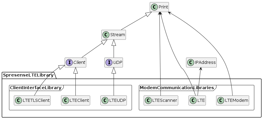
The Spresense LTE library provides classes belonging to two categories:
One category consists of library classes that communicate with the modem, and the other one consists of library classes supporting e.g. Ethernet or WiFi.
This library class implements the client interface.
The library classes belonging to the two categories are described below.
2.10.2. Modem communication classes
There are three library classes that communicate with the modem.
-
LTE
-
LTEScanner
-
LTEModem
These provide functionality similar to the Arduino GSM library.
2.10.2.1. Modem status
The library modem communication class manages the state of the modem.
Table 16 shows the different modem states.
| status | description |
|---|---|
OFF |
The modem is powered off. |
IDLE |
The modem is powered on but wireless is off. |
CONNECTING |
Registering modem to LTE network. |
SEARCHING |
Radio is turned on and the LTE network is being searched. |
READY |
The modem is registered to the LTE network and has been assigned an IP address. |
ERROR |
The modem is in an error state. |
State transitions happen either because of class method being called or by events occurring in the communication with the LTE network.
The state transition diagram of the modem is shown in Figure 14.
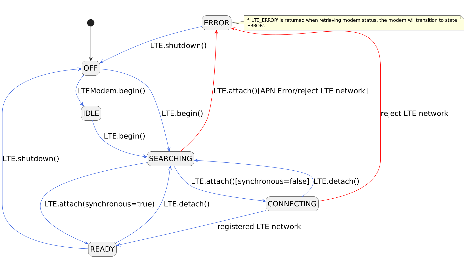
The functions provided by the modem communication class are described below.
2.10.2.2. LTE class
Provides functionality for registering the modem with the LTE network and assigning an IP address to the modem.
- Exploring the LTE network
-
In order to register your modem in the LTE network, it is necessary to establish a communication path between the modem and the network.
First, use the begin() method to turn the modem on and start scanning the LTE network. The begin() method is defined as follows.
begin(
    char* pinCode = NULL,
    bool restart = true,
bool synchronous = true)-
pinCodeis the the SIM PIN code. If your SIM card has a PIN code, please provide it as a string (e.g. "1234").
If your SIM does not have a PIN lock code, then set pinCode to NULL.
|
If the PIN unlock fails, the modem will go into |
-
restartis the restart flag. If set totruethe modem will be restarted before it starts exploring the LTE network. If set tofalsethe modem will start and begin exploring the LTE network directly. -
synchronoussets the method execution mode. If set tofalse, begin() will be executed asynchronously.
|
Asynchronous execution is currently not supported, so synchronous mode will be used even if the parameter is set to |
By default the PIN unlock code is set to NULL and both the reboot flag and the sync flag are set to true.
The return value indicates the modem state. It is SEARCHING when a LTE network search is started.
|
If begin() fails, the
|
- Register the modem to the LTE network
-
Once you have started exploring the LTE network, use the attach() method to register the modem with the it and build a communication path between the modem and the network.
|
Depending on your coverage, it may take a few minutes for the modem to register. |
The attach() method is defined as follows
attach(
    char *apn,
    char *userName = NULL,
    char* password = NULL,
    LTENetworkAuthType authType = LTE_NET_AUTHTYPE_CHAP,
    LTENetworkIPType ipType = LTE_NET_IPTYPE_V4V6,
    bool synchronous = true)
The parameters given to the attach() method define the APN (Access Point Name), network login credentials and method behavior. The APN specifies the connection point required for communicating in LTE networks. The APN parameters are shown in Table 18.
| parameter | description |
|---|---|
apn |
Access point name |
userName |
User name. Default setting is unspecified ( |
password |
Password. Default setting is unspecified ( |
authType |
Authentication type. Choose from |
ipType |
APN protocol. Select from |
|
Set the APN parameters according to the SIM card you are using. |
If the synchronous parameter is set to true, the attach() method will return when the modem is done registering to the LTE network.
If set to false, the attach() method will return immediately while modem registration is done in asynchronously.
The return value indicates the status of the modem.
-
If the synchronization flag is
true, theREADYstatus is returned when the modem is registered with the LTE network. -
If the synchronization flag is
false, theCONNECTINGstatus is returned when the modem registration process is started.
To verify that the modem registration is complete, check the status of the modem with the getStatus() method. It will returnREADYwhen it the modem is registered to the LTE network.
|
If the attach() method fails, the
|
- Get the IP address
-
You can use the getIPAddress() method to get the IP address assigned to the modem by the LTE network.
|
If the modem is not in the |
- To get the time
-
You can use the getTime() method to get the number of seconds since Epoch (Epoch; 1970-01-01 00:00:00 (UTC)).
|
If the modem is not in the |
- Detach the modem from the LTE network
-
You can use the detach() method to detach the modem from the network and release the IP address assigned to the modem.
|
If the modem is in the |
- Turn off the power of the modem
-
The shutdown() method can be used to turn off the power of the modem.
|
If the modem is in the |
2.10.2.3. LTEScanner class
This class provides a function to acquire the Received Signal Strength Indicator (RSSI) received by the modem and the name of the operator used for communication.
- Retrieving the network signal strength (RSSI)
-
Use the getSignalStrength() method to get the strength of the signal that the modem is receiving. The unit is dBm. If there is no network coverage, the value "N/A" will be returned.
|
In order to use this method, the modem status must first be set to |
- Get the name of the network operator
-
You can use the getCurrentCarrier() method to get the name of the operator that registered the modem.
|
In order to use this method, the modem must first be set to state |
2.10.2.4. LTEModem class
Provides a function to obtain the firmware version and International Mobile Equipment Identity (IMEI) of a modem.
|
To use the functions of this class, the modem status must first be set to |
- Get the modem firmware version
-
Use the getFirmwareVersion() method to get the firmware version of your modem.
- Obtaining the International Mobile Equipment Identity (IMEI)
-
You can use the getIMEI() method to get the International Mobile Equipment Identity (IMEI).
2.10.3. Client Interface Library Classes
There are three client interface library classes.
-
LTEClient
-
LTETLSClient
-
LTEUDP
The LTE library is trying to be as compatible as possible with Ethernet library and WiFi library to enable porting from the Arduino Ethernet and Arduino WiFi libraries.
It is not possible to run Ethernet-compatible code as-is but with modifications specific to the LTE library, e.g. for the LTE network registration process, it should be able to run it.
The functions provided by the client interface library class are described below.
2.10.3.1. LTEClient class
Provides client communication functions using the TCP protocol.
It realizes the Arduino Client interface.
|
In order to use the LTEClient class, the modem must first be set to state |
For details on the methods, see the API Reference Manual LTE Client API.
2.10.3.2. LTETLSClient class
Provides client communication functions using the TLS protocol.
It realizes the Arduino Client interface.
|
In order to use the LTEClient class, the modem must first be set to state |
For details on the methods, see the API Reference Manual LTE TLS Client API.
- Configuring certificates
-
This section describes how to configure the root certificate, client certificate, and private key used in the TLS protocol.
There are methods available in this class that support storing the certificates and key on the board in three different ways. Please select the one most suitable for your environment:-
Place the certificate and private key files on a microSD card etc.
An example of using a microSD card for this is described in Checking the operation of HTTP Client using TLS protocol. -
Generate an array in PEM format using some program and store it in the source code.
-
Generate an array in DER format using some program and store it in the source code.
-
2.10.3.3. LTEUDP class
Provides client communication functions using the UDP protocol.
It realizes the Arduino UDP interface.
|
In order to use the LTEClient class, the modem must first be set to state |
For details on the methods, please refer to the API Reference Manual LTE UDP API.
2.10.4. Explanation with sample code
This is an actual tutorial on how to use Spresense LTE using the LTE sample code included in the Spresense Arduino Package.
For more details, please refer to LTE tutorial.
Now, let’s go ahead and create your original IoT device using Spresense LTE!
2.11. MultiCore MP Library
2.11.1. Overview
MultiCore MP Library is a library to support multi-core programming in Arduino environment. CPU core that is launched by default is called MainCore, and CPU cores are booted from MainCore are called SubCore. The total number of SubCore are 5, from SubCore 1 to SubCore 5.
You can select MainCore and SubCore 1 ~ 5 by selecting Tools→ Core in Arduino IDE menu. Program on each core and load the binary compiled for each core on the Spresense board and run it. By using the MP library, you can program each core and can work them.
2.11.2. Functions
The MP library mainly provides the following functions:
-
Start and stop SubCore(s)
-
Inter-core communication function
-
Inter-core exclusive control function
-
Allocate and release shared memory
-
Exclusive log output function
For details on each API, refer to the API Reference Manual MP Library API.
2.11.2.1. MP class
By including MP.h, an object named MP will be created.
#include <MP.h>The following table is a list of functions provided by the MP class.
Please note some functions are different between MainCore and SubCore, and some functions are not supported by SubCore (*: supported, -: not supported)
| Function | Description | MainCore | SubCore |
|---|---|---|---|
MP.begin() |
Control multi-core boot. |
* |
* |
MP.end() |
Control multi-core shutdown. |
* |
* |
MP.Send() |
Send data to the specified core. |
* |
* |
MP.Recv() |
Receive data from the specified core. |
* |
* |
MP.RecvTimeout() |
Set the receiver mode and timeout value for Recv(). |
* |
* |
MP.GetRecvTimeout() |
Get the value set by RecvTimeout(). |
* |
* |
MP.Virt2Phys() |
Convert the virtual address specified by the argument to a physical address. Physical address map is common for all cores. On the other hand, virtual address map is different for each core. Since SubCore runs on virtual address, use this function to convert it to a physical address when sending an address to other core. |
* |
* |
MP.GetMemoryInfo() |
Get the status of application’s available memory. |
* |
* |
MP.EnableConsole() |
Enable input from serial monitor (Serial). |
* |
* |
MP.DisableConsole() |
Disable input from serial monitor (Serial). |
* |
* |
MP.AllocSharedMemory() |
Allocate shared memory and return the first physical address. Allocation and release of shared memory are in 128 Kbyte units. Allocate 128 Kbyte aligned memory from the size specified in the argument. If it cannot allocate due to lack of memory, NULL is returned. |
* |
- |
MP.FreeSharedMemory() |
Release the shared memory by passing the address allocated by AllocSharedMemory(). |
* |
- |
2.11.2.2. MPMutex class
This provides functions for exclusive control between multiple cores. Create a mutex object by specifying MP_MUTEX_ID number (0 to 10) as an argument.
#include <MPMutex.h>

MPMutex mutex(MP_MUTEX_ID0);
The functions provided by MPMutex are shown below.
| Function | Description | MainCore | SubCore |
|---|---|---|---|
mutex.Trylock() |
Lock mutex. If it can be locked, return 0. If it cannot be locked, return non-zero value. |
* |
* |
mutex.Unlock() |
Unlock mutex locked by Trylock(). If it can be unlocked, return 0. If it cannot be unlocked, return non-zero value. |
* |
* |
2.11.2.3. MPLog() function
This is a function to output log in multi-core environment.
| Function | Description | MainCore | SubCore |
|---|---|---|---|
MPLog() |
This is a function macro to output log with exclusive control between cores. The arguments can use the same format as the general printf(). |
* |
* |
2.11.2.4. Application memory
The total SRAM memory for the application is 1.5 MBytes (= 1536 KBytes). The memory is divided into 128 KByte x 12 memory tiles. Each CPU and SRAM are connected with bus matrix to units of memory tiles. If only one CPU accesses a tile, the CPU can read and write the SRAM without wait-cycles. (This means the same performance as cache on general CPU architectures). On the other hand, if multiple CPUs access the same memory tile, memory access is slowed down. To prevent the above access conflict, each SubCore is using the dedicated memory tiles and runs on the memory tiles.
The mapping of SRAM 1.5 MByte in Arduino environment is shown below.
MainCore uses the first 6 tiles (768 KBytes). The remaining 6 tiles (768 KBytes) are shared and used by SubCore and other libraries.
In the figure above, 256 KByte is allocated to SubCore1 and 128 KByte is allocated to SubCore2.
SubCore works on a virtual address beginning from address 0.
If it is necessary to refer to a common address for inter-CPU communication etc, convert it to a physical address with MP.Virt2Phys().
In addition, the second half of 768 KByte shared memory may be used by various libraries besides SubCore. The used memory size for each library and each usecase is shown below.
| Library | UseCase | Used Memory Size |
|---|---|---|
Audio, Sensing |
For various buffers |
256 KByte |
Audio |
For loading the |
128 KByte |
Audio |
For loading the |
256 KByte |
Audio |
For loading the |
256 KByte |
Audio |
For loading the |
128 KByte |
DNNRT |
For loading the |
128 KByte |
The memory size required for SubCore depends on the user application. When compiling a sketch, the following message is output to the log of compilation result. This value shows the memory size that has been allocated for the SubCore.
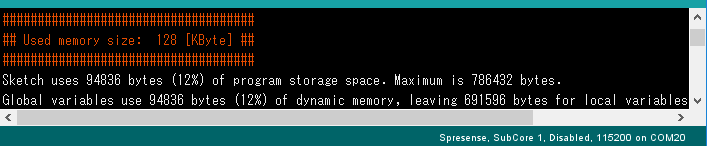
In use case of user application, it may not be possible to operate with insufficient memory.
You can check the memory usage by using MP.GetMemoryInfo().
Example code is shown below.
{
  int usedMem, freeMem, largestFreeMem;

  MP.GetMemoryInfo(usedMem, freeMem, largestFreeMem);

  MPLog("Used:%4d [KB] / Free:%4d [KB] (Largest:%4d [KB])\n",
        usedMem / 1024, freeMem / 1024, largestFreeMem / 1024);
}
2.11.2.5. Boot SubCore
Call MP.begin(1~5) from MainCore to start a SubCore by using number (1 to 5) as an argument.
On the started SubCore side, the completion of boot up is notified by calling MP.begin() without an argument.
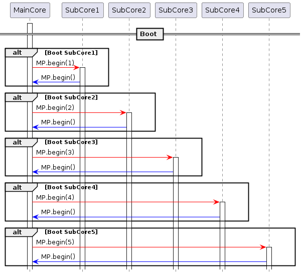
2.11.2.6. Shutdown SubCore
Call MP.end(1~5) from MainCore to shutdown a SubCore by using number (1 to 5) as an argument.
The specified SubCore is shutdowned.
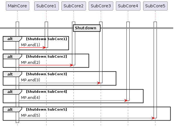
2.11.2.7. Communication between cores
You can send and receive arbitrary data using the MP.Send() and MP.Recv() functions.
There are 3 modes for waiting for reception, and the mode is set by MP.RecvTimeout().
The default is MP_RECV_BLOCKING.
-
MP_RECV_BLOCKING (0): The mode for reception to wait forever until it receives data. (Default)
-
MP_RECV_POLLING (0xffffffff): The mode for polling reception. If there is no received data when Recv() is called, it will be returned immediately. In this mode there is no waiting for reception.
-
Time value (Other value than above): Set the waiting timeout time (milliseconds). It will wait for the specified time when calling Recv(), and it will be timed out if the received data does not come.
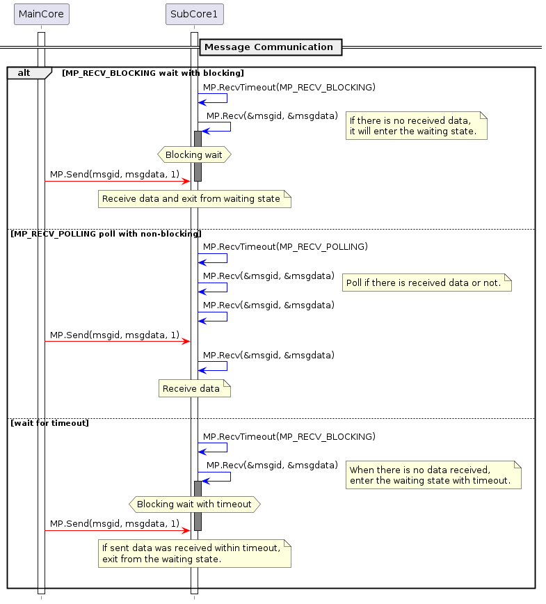
There are two communication methods for MP.Send() and MP.Receive(): passing data and passing address.
-
Communication with data
-
Prototype
int MP.Send(int8_t msgid, uint32_t msgdata, int subid)
int MP.Recv(int8_t *msgid, uint32_t *msgdata, int subid) -
Argument
msgid: User can define zero or a positive Message ID (8 bit signed data). User cannot use a negative value.
msgdata: User can define arbitrary Message Data (32 bit data).
subid: Specify a SubCore number to communicate. If subid is 0 (optional), it communicates with MainCore. -
Return
Send() returns 0 if successful, non-zero if error.
Recv() returnsmsgidif successful, negative value if error. -
Description
Send both Message ID and Message Data by Send() and receive these values by Recv().
Send() runs asynchronously. It has an 8-stage transmit FIFO buffer internally, and Send() function immediately returns 0 after pushing transmission data into the FIFO buffer and before the destination core receives data. If this 8-stage buffer becomes full, Send() function returns -EAGAIN(-11).
On the other hand, the receiver also has an 8-stage receive FIFO buffer. If this receive buffer becomes full, it is judged as the system abnormal condition and the program assert. If this happens, please check whether the receiving core is working properly or the communication load is too high.
-
-
Communication with address
-
Prototype
int Send(int8_t msgid, void *msgaddr, int subid)
int Recv(int8_t *msgid, void *msgaddr, int subid) -
Argument
msgid: User can define zero or a positive Message ID (8 bit signed data). User cannot use a negative value.
msgdata: User can define arbitrary Message Address (pointer).
subid: Specify a SubCore number to communicate. If subid is noting, it communicates with MainCore. -
Return
Send() returns 0 if successful, non-zero if error.
Recv() returnsmsgidif successful, negative value if error. -
Description
Send both Message ID and Message Address by Send() and receive these values by Recv(). This function is used when you send only the pointer address of data to communicate. When sending an address from SubCore, the conversion from virtual address to physical address is required. The address conversion of msgaddr is performed inside the Send() function. However, if the msgaddr pointer points the data with address information, you have to convert the address from virtual to physical address.
As mentioned above, Send() is asynchronous. Send() cannot guarantee that the destination core has received the data. Therefore, if the data pointed to by the msgaddr pointer is rewritten immediately after Send(), the received data is broken. To support synchronous communication, you have to implement the communication for acknowledge. Or, it is necessary to add a flag to guarantee data in the data packet.
-
For usage of Send()/Recv() function, please refer to Message in Examples.
- Message/MessageData
-
Example for data communication
- Message/MessageHello
-
Example for address communication
2.11.2.8. Available libraries from SubCore
All of Arduino core libraries are available from SubCore.
Some Spresense-specific libraries cannot be used from SubCore. If you include them, the following error message is output at compile time.
XXX library is NOT supported by SubCore.
The following libraries are available from SubCore.
| Library | MainCore | SubCore | Description |
|---|---|---|---|
MP |
〇 |
〇 |
|
RTC |
〇 |
〇 |
Alarm function is not available for SubCore. |
SPI |
〇 |
〇 |
|
Servo |
〇 |
〇 |
|
SoftwareSerial |
〇 |
〇 |
|
Watchdog |
〇 |
〇 |
|
Wire |
〇 |
〇 |
|
Audio |
〇 |
- |
|
Camera |
〇 |
- |
|
DNNRT |
〇 |
- |
|
GNSS |
〇 |
- |
|
LowPower |
〇 |
- |
|
LTE |
〇 |
- |
|
Sensing |
〇 |
- |
|
Storage (EEPROM, eMMC, File, Flash, SDHCI) |
〇 |
- |
2.11.2.9. SubCore Programming TIPS
How to increase heap size of SubCore program
The memory size required by SubCore is determined automatically at compile time, hereby explains the detailed logic.
The size up to .stack is determined statically at compile time, but the size of .heap depends on the user program.
A minimum 32 KBytes of heap memory is assigned, and the final total size is 128 KByte alignment.
The heap memory is allocated up to the aligned upper limit.

By the above rule, a heap area of at least 32 KBytes is assigned. However, the user programs may need more heap space. If you want to increase the heap area, use the USER_HEAP_SIZE() macro on your sketch.
USER_HEAP_SIZE(64 * 1024);In this case, the heap memory of 64 KByte or more is always assigned.
Compile options to identify SubCore
When building SubCore, -DSUBCORE=core number is specified as compile option.
If you want to divide the code by ifdef for each core in common source code, please refer to the following.
#if   (SUBCORE == 1)
// SubCore1 building

#elif (SUBCORE == 2)
// SubCore2 building

#elif (SUBCORE == 3)
// SubCore3 building

#elif (SUBCORE == 4)
// SubCore4 building

#elif (SUBCORE == 5)
// SubCore5 building

#else
// MainCore building

#endif
By applying the following description to user sketch, you can prevent the wrong core from being selected and built or uploaded.
-
Build error if SubCore is selected in MainCore’s sketch
#ifdef SUBCORE
#error "Core selection is wrong!!"
#endif-
Build error if MainCore is selected in SubCore’s sketch
#ifndef SUBCORE
#error "Core selection is wrong!!"
#endif-
Build error if the other core is selected in SubCore1’s sketch
#if (SUBCORE != 1)
#error "Core selection is wrong!!"
#endif
Sketch directory structure
You may want to refer to the common header file between MainCore and SubCore.
As a suggestion, for example, you can include a common common.h header file by using the following directory structure.

In your SubSketch.ino,
#include "common.h"In your MainSketch.ino,
#include "SubSketch/common.h"Another option is to put a common header file in the place of libraries in your Arduino environment.
If there is the header file under libraries, it is possible to include from any sketch.
You can add the header file into your libraries by specifying the folder containing the header files
from the Arduino IDE menu Sketch→ Include Library→ Add .ZIP Library ….
2.11.3. Examples
For basic usage of the MP library, refer to example sketches under Arduino IDE menu File→ Examples→ Examples for Spresense→ MultiCore MP.
| Example | Description |
|---|---|
Boot |
This is an example to boot 4 SubCores. Each launched SubCore controls a separate LED. |
Message/MessageData |
This is an example to communicate with data between MainCore and SubCore. |
Message/MessageHello |
This is an example to communicate with address between MainCore and SubCore. |
Mutex |
This is example for exclusive control using MPMutex between multi-core. |
SharedMemory |
This is an example to allocate and free the shared memory from MainCore. |
Shell |
This is an example for SubCore to run shell. |
AudioFFT |
This is an example for advanced application using SubCore. MainCore captures PCM 4ch data using Audio library and send their data to SubCore. SubCore displays the peak frequency by calculating FFT (Fast Fourier Transform) in real-time. It is possible to display the time series data to Arduino IDE serial plotter. |
2.12. RTC Library
RTC library controls the Spresense’s Real-Time Clock which is just a monotonically increasing counter with the initial value of 0. RTC is managed as unix time and the initial value of 0 means January 1, 1970 at 00:00:00.
RTC can keep the time during the sleep state such as Deep Sleep and Cold Sleep.
When the power is turned off, the RTC counter is reset to the zero value.
| When you use this library, please first, call RTC.begin(). It takes about 2 seconds until the RTC XTAL is stable after power is supplied. After returning from RTC.begin(), you can use the various RTC functions. |
This library provides some features. For more details of this library, see the API reference RTC Library API.
-
RTC.setTime() … Set the RTC clock
-
RTC.getTime() … Get the RTC clock
-
RTC.attachAlarm() … Register the RTC alarm handler
-
RTC.detachAlarm() … Unregister the RTC alarm handler
-
RTC.setAlarm() … Set the RTC alarm
-
RTC.setAlarmSeconds() … Set the RTC relative alarm of the specified seconds
-
RTC.cancelAlarm() … Cancel the RTC alarm
For basic usage of this library, see the examples of this library
through the Arduino IDE menu File → Examples → Examples for Spresense RTC.
In addition to the RTC library, you can use the POSIX standard APIs such as strftime() and clock_gettime(CLOCK_REALTIME, tp) by adding #include <time.h>.
For more information, refer to NuttX User’s Manual.
Local time has been disabled in the NuttX configuration, so localtime() is not supported.
2.13. SDHCI Library
2.13.1. Overview
The SDHCI library is a library for accessing micro SD on the Spresense extension board. The card can be accessed from your program or optionally you can configure the system to access the SD Card via USB port on the Spresense extension board.
The SDHCI library has an API structure similar to the Arduino SD library, and it can be easily ported from the existing sketch using the SD library.
-
SD and SDHC cards are supported, but SDXC cards is not supported.
-
Formats of FAT12, FAT16 and FAT32 are supported, exFAT is not supported.
-
Capacity of up to 32 GB is supported.
Unlike using a simple SPI interface, Spresense accesses the SD card using dedicated hardware for SD Host Controller Interface, which has the following features:
-
Since the SD card is connected with a dedicated port, the SPI pins are not required. The SPI pins can be used for other purposes.
-
It is very fast compared with SPI communication. SDR25 transfer mode, at approximately 25 MB per second, is supported.
A distinctive feature of the SDHCI Library is providing the USB MSC (Mass Storage Class) function. You can directly access the file on the SD card by connecting to the USB on the Spresense extension board from your PC.
| If the current time of 1980/1/1 or later is set by Section 2.12, the created and modified timestamps of files and directories based on the RTC time will be recorded in the file system. |
2.13.2. Functions
See API references SD card Library API for the details.
SDHCI library doesn’t have an instance of SDClass, therefore please define as below in your sketch.
#include <SDHCI.h>
SDClass SD;| Function | Description |
|---|---|
SD.begin() |
Check if the SD card is mounted. After this function returns |
SD.beginUsbMsc() |
Start USB MSC (Mass Storage Class) function. |
SD.endUsbMsc() |
Stop USB MSC (Mass Storage Class) function. |
SD.format() |
Format the SD card with FAT32 filesystem by default. |
SD.open() |
Opens a file on the SD card. When the file is opened for writing, it will be created if it doesn’t exist yet. |
SD.exists() |
Tests whether a file or directory exists on the SD card. |
SD.mkdir() |
Create a directory on the SD card. |
SD.rmdir() |
Remove a directory from the SD card.. |
SD.remove() |
Remove a file from the SD card. |
2.13.3. Examples
Use the SD card formatted with FAT32. Three sample sketches using SDHCI library are provided here:
| Example | Description |
|---|---|
This is an example to read and write files on the SD card. |
|
This is a sample for the USB MSC function. If you run this sketch, the SD card on the Spresense extension board will be mounted as a drive on the PC and you will be able to access the SD card directly from the PC. |
|
This is an application combining USB MSC function and file operations. |
2.14. Sensing Library
Spresense has the function of low-power always sensing and the high performance of edge computing. It is possible to create a sensor (called a logic sensor) that can output abstract data that fused various sensor data by signal processing / AI processing, etc., resulting in a smaller amount of data.
The Sensing Library provide a framework to use and create logic sensors by such sensor fusion.
Logic sensors can recognize and signal process that are used Multi Core, which is a feature of Spresense, to perform signal / recognition processing with other cores (hereinafter these cores are called DSP).
- Key Features of the Sensing Library
-
-
Based on Publish-Subscribe Architecture, it is easy to execute and change the fusions of multiple sensors
-
It can use data that the sensor driver created by Arduino-supplied ecosystem sensor, and can create logic sensor and subscribed by Arduino application, the same function as SDK can be used from Arduino
-
|
Arduino library is basically a wrapper library the functions and APIs possessed by the SDK. For more information, please refer to the SDK side. |
2.14.1. Architecture and data flow
First, here is the Sensor Framework of Spresense.
Please refer to Sensor Fusion Framework for this.
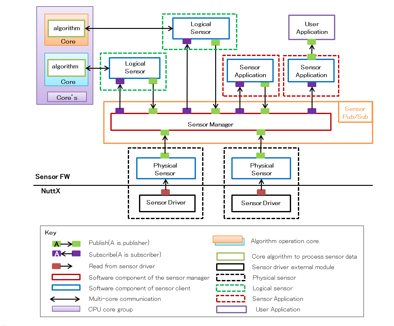
Next, the following is the architecture of the Sensing library for Arduino.
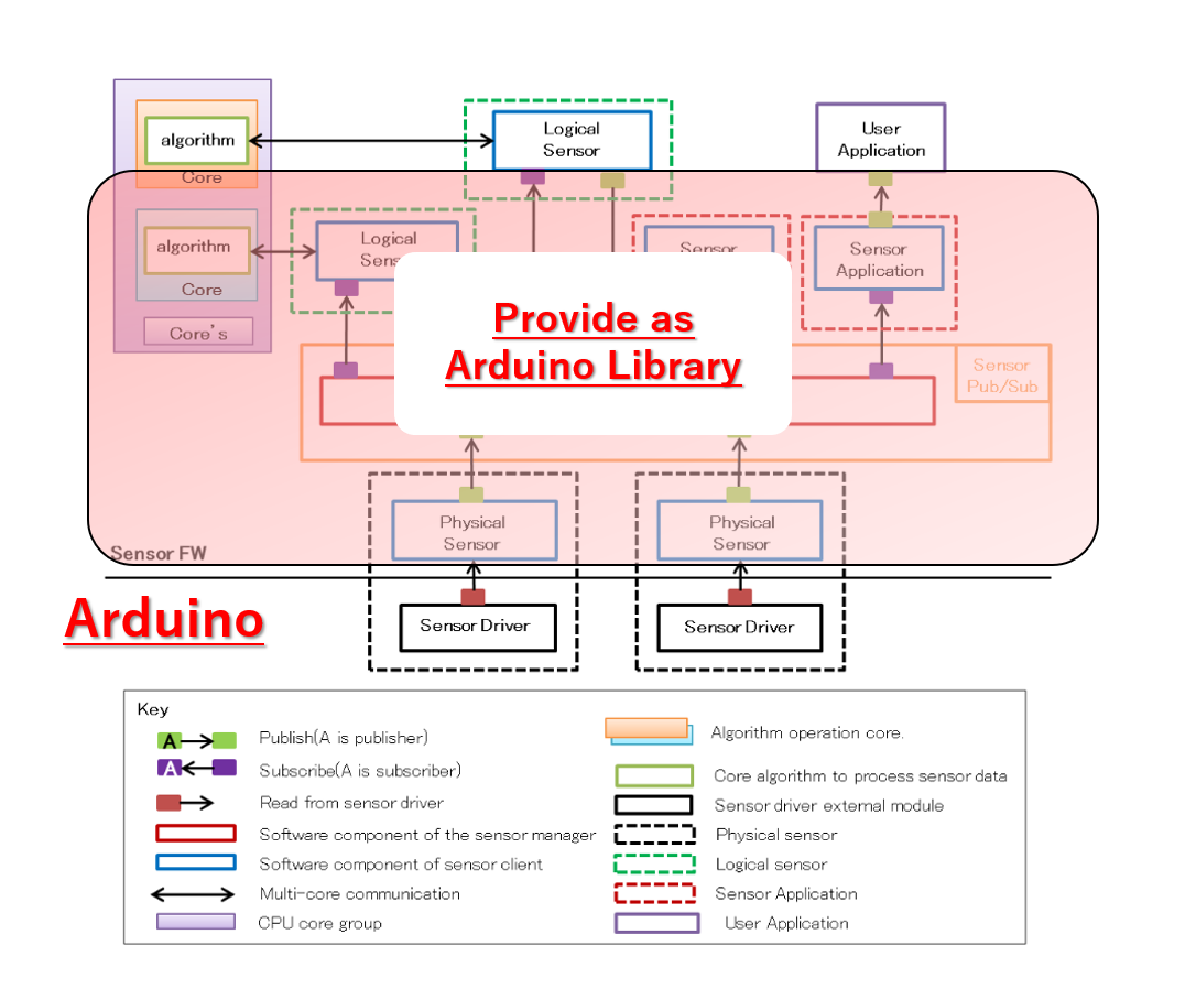
By providing the Sensor Framework part provided by Spresense SDK as a "Sensing" library, the functionality equivalent to the SDK is realized.
For Arduino developers, we provide a framework for creating sophisticated logic sensors and applications using these sensors.
You can also create applications that use logic sensors that better meet your needs by creating logic sensors with a higher degree of abstraction yourself.
- Classes of Sensing Library
-
-
SensorManagerClass:
It is a wrapper class of the class (Sensor Manager) that manages each sensor client in SDK. -
SensorClient:
the base class of sensorclient which is an element of each sensor. Users do not call this class directly.
Inherit this class if you want to create your own logic sensor.-
AccelSensorClass:
Each sensor client can use acceleration data by publishing the sensor data acquired from the physical sensor client of the acceleration sensor with the sensor sensor driver at Arduino. -
ApplicationSensorClass:
The application is a sensor client for subscribing sensor data.-
StepCountReaderClass:
This is a sensor client for reading data of step counter sensor in application. It is created inheriting from ApplicationSensorClass.
-
-
AesmClass:
This is a logical sensor client for pedometer algorithm (AESM: Activity Engine and StepMeter) provided by Spresense SDK .
It use an acceleration sensor.
Because of logic sensor provided by SDK, publish/subscribe processing from Arduino is unnecessary.
-
-
2.14.2. API reference of each classes
It is shown below, the API reference for each classes.
2.14.2.2. SensorClient
It is shown below, the API of SensorClient. This class is a base class for each sensor client.
2.14.2.3. AccelSensorClass
The physical sensor clients for acceleration sensing are also provided as a library. It is made in the inheritance of SensorClient.
2.14.2.4. ApplicationSensorClass
Application sensors are sensor clients for passing sensor data to applications. Therefore, only subscribe is implemented.
2.14.3. About the sample sketch
2.14.3.1. Step Counter sample
Here, for a Sensing sample, we provide the sample using StepCounter provided by SONY.
| This sample requires to update to the Spresense SDK v1.3.0 or later bootloader. |
The Step Counter function in Spresense SDK consists of the following.
Please refer to Sensor Fusion Framework for this.
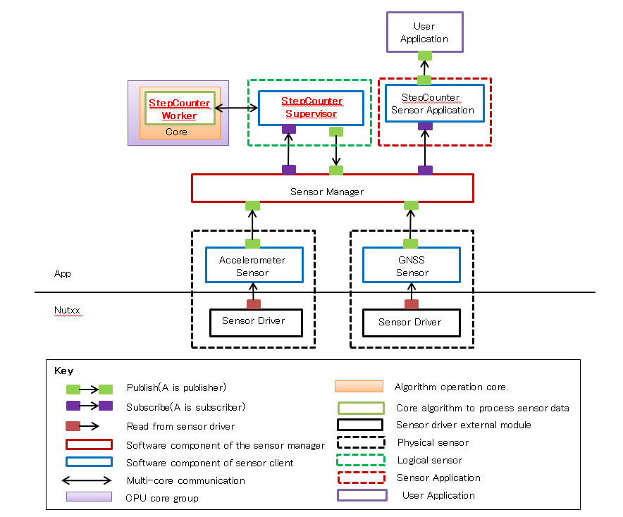
For Arduino, the part of Sensing library shown in the figure below is provided as a library.
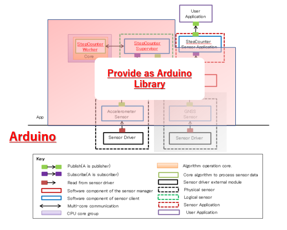
A sample sketch can be implemented by implementing the part that writes the acceleration sensor to the reading framework and the part that reads the generated StepCounter data.
The following is the sequence.
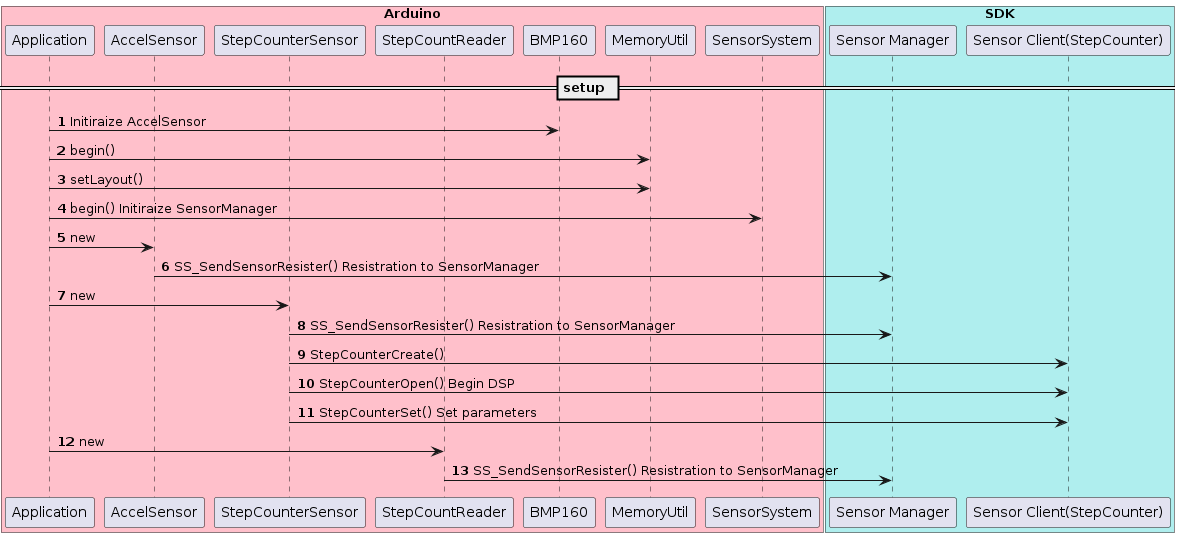

In this way, StepCounter data can be obtained by implementing it.
For details on how to use, please refer to Tutorials.
2.15. Servo Library
The Servo library is one of the available libraries on Spresense board to control the RC Servo.
The Servo library is used the same way as the original Arduino servo library. The Arduino language reference have documented the Arduino Servo library and these instructions can be used for the Spresense Servo library too.
Spresense has 4 pins that can be used by the Servo library. These are the PWM pins on the extension board:
-
D06 PWM0
-
D05 PWM1
-
D09 PWM2
-
D03 PWM3
Most Servos are designed for a 5V power supply and draw considerable power, so you should power them from a separate supply, not the +5V pin on the Extension board.
The extension board interface voltage is set by the IOREF jumper to 3.3 or 5V. Most radio control servos can use 3.3 or 5V control signals.
2.16. SignalProcessing Library
The Spresense SignalProcessing library is the library for basic signal processing for sensing and audio.
The main features of the SignalProcessing library
-
Performs multi-channel FFT processing.
-
Performs bi-quadratic IIR filtering.
Input Data
-
Input multi-channel data interleaved for each channel.
Out Data
-
FFT: Outputs the FFT result for each channel.
-
IIR: Outputs interleaved multi-channel data after signal processing.
| Considering memory resources, processing time, etc., each signal processing only supports 16-bit length. |
2.16.1. Library Structure
The SignalProcessing library consists of three objects.
-
FFTClass
Object that performs FFT processing -
IIR Class
An object that performs IIR filtering -
RingBuff
the ringbuffer for storing multi-channel input data
(The user does not need to be aware.)
The data flow in each objects has the following structure.
-
FFT

-
IIR
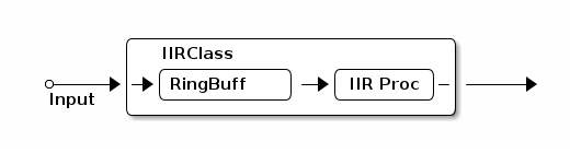
Input data is stored in the RingBuff class through FFT/IIR class IF.
When receiving a request of get , it outputs data while performing each signal processing.
2.16.2. Multi-channel data of input/output
The multi-channel data of input/output should have the following interleaved data format.
-
Incase of 16bit-length
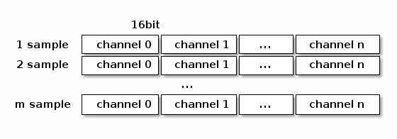
-
Incase of 24bit-length
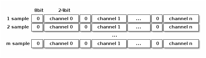
| In the case of 24 bits, please align with 32 bits and store the data in the lower 24 bits. |
2.16.3. FFT library details
The following parameters are statically specified for each instance (specified at compile time).
-
Maximum number of channels
Allocate of memory resources for the maximum number of channels needed. The actual number of channels do not have to be the same as this number, but have to be less than this. -
Number of FFT taps
Specify the number of FFT taps to be executed. The number of taps that can be specified is as follows.
32 / 64 / 128 / 256 / 512 / 1024 / 2048 / 4096
| If you increase the maximum channels and the number of taps, the memory resources will be used more, so please set it according to your purpose. |
| The number of taps is specified at compile time by the template variable, so if you want to change the number of taps at the time of execution, create plural instances with different number of taps and use them. |
The following parameters can be changed via begin.
-
Window function
Specify the window function to be applied to FFT. The window function only supports the following.
-Rectangular window
-Hanning window
-Humming window
-Flattop window
-
Overlap size
When performing FFT by applying a window function etc., it is possible to overlap the input data. Specify the number of overlapping samples.
It is possible to specify from 0 to half the size of the number of FFT taps.
2.16.4. IIR library details
The following parameters are statically specified for each instance (specified at compile time).
-
Maximum number of channels
Allocate of memory resources for the maximum number of channels needed. The actual number of channels do not have to be the same as this number, but have to be less than this. -
Bit length
It is the bit length of the input data. Currently, only 16 bit is supported. -
Frame size
Specify the number of samples for one execution of IIR processing. Decreasing the value reduces the delay until processing, but increases the overhead.
The following parameters can be changed via begin.
-
Filter mode
Specifies what kind of filter the IIR will implement. The following modes can be set.
-HPF (High Pass Filter)
-LPF (Low Pass Filter)
-BPF (Band Pass Filter)
-BEF (Band Elimination Filter)
-
Cutoff frequency (HFP/BPF)/Center frequency (BPF/BEF)
Specifies the cutoff frequency or center frequency of the filter. -
Q value
Specifies the Q value of the filter. -
Frame size
Specifies the number of samples to be executed once for IIR processing. Decreasing it will reduce the processing delay, but will increase the overhead. The default value is 768 samples. -
Output channel mapping
Specifies the mode of channel mapping for filter results. You can select either of the following.-
Interleave (interleave each channels output )
-
Planar (output per channels)
-
-
Sampling rate
Specifies the sampling rate of the input data. The default value is 48000Hz.
2.16.5. How to use (sequence)
2.16.5.1. FFT sequence
The sequence of FFT library is as follows.
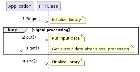
-
Please refer to the above for the parameters that can be specified in
begin. -
The number of input samples in
putdoes not have to be the same as the number of taps in FFT. -
If the library have sufficient input data (more than the number of FFT taps) when you call
get, you can get the signal processing result.
If signal processing is successful, the number of input data samples (in the case of FFT, the number of taps minus the number of overlapping samples) discarded in this processing is returned. By inputting only the discarded samples, the next signal processing is possible. -
The number of data will be equal to the number of taps regardless of overlapping samples.
| The input buffer will be overwritten with old data if input exceeds the buffer size. Be careful not to overflow the input buffer. |
2.16.5.2. IIR sequence
The sequence of IIR library is as follows.
Sequence with output format Planar

| 1 | Please refer to the above for the parameters that can be specified in begin .
If you want the output format to be Planar, you must either not specify the output format with begin or specify the output format with Planar. |
||
| 2 | The number of input samples in put does not have to be the same as the number of frame samples in IIR. |
||
| 3 | If the library have sufficient input data (more than the number of frame samples) when you call get, you can get the signal processing result.If signal processing is successful, the number of input data samples (in the case of IIR, the number of frame samples) discarded in this processing is returned. By inputting only the discarded samples, the next signal processing is possible. If you specify the output format to Planar on begin, you should
call get function with channel number for each channel.
|
||
| 4 |
end releases various resources. |
Sequence with output format Interleave
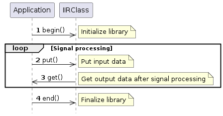
| 1 | Please refer to the above for the parameters that can be specified in begin .
If you want the output format to be Interleave, you must specify the output format with Interleave. |
||
| 2 | The number of input samples in put does not have to be the same as the number of frame samples in IIR. |
||
| 3 | If the library have sufficient input data (more than the number of frame samples) when you call get, you can get the signal processing result.If signal processing is successful, the number of input data samples (in the case of IIR, the number of frame samples) discarded in this processing is returned. By inputting only the discarded samples, the next signal processing is possible.
|
||
| 4 |
end releases various resources. |
2.16.6. About API details
For details on each API, refer to the API reference.
Signal Processing Libraries API
2.16.7. About error information
When an error occurs in APIs such as begin,put, and get,
you can get what is the cause of the error with getErrorCause.
The following is the error code.
| Error Code | Value | Description |
|---|---|---|
ECODE_OK |
0 |
Normal termination |
ERR_CH_NUM |
-1 |
The number of channels specification error |
ERR_FORMAT |
-2 |
Output format specification error |
ERR_MEMORY |
-3 |
Memory allocation failure |
ERR_FILTER_TYPE |
-4 |
Filter type specification error |
ERR_FRAME_SIZE |
-5 |
Frame size specification error |
ERR_BUF_FULL |
-6 |
Failed to get write area for buffer |
ERR_FS |
-7 |
Sampling rate specification error |
In the event of an error, get returns an error code in the return value, and at the same time,getErrorCause can be used to get the cause of the error.
|
2.17. Software Serial Library
The Spresense Arduino Library natively supports 2 serial ports: the header pins D0 D1 and the main board USB port. The SoftwareSerial library provides serial communication on any digital pins of the Spresense.
The SoftwareSerial library is used the same as the SoftwareSerial Library described in Arduino language reference and is compatible with the examples given on that page.
|
The pin numbers of the receiver and transmitter pins are specified as arguments in SoftwareSerial(uint8_t receivePin, uint8_t transmitPin). Both pins are used by switching to GPIO mode, and switching to GPIO mode is done in units of pin groups. For details on pin groups, see Connector Pin List (xlsx) for more information. The receiver pin |
2.18. SPI Library
The SPI library has been developed to allow the use of SPI devices with Spresense.
The SPI library is used in the same way as SPI Library described in Arduino language reference.
Spresense has multiple SPI interfaces for main board and extension board respectively.
The pins allocated to SPI are shown below.
| SPI instance | Connector | MOSI | MISO | SCK | SS | IO voltage |
|---|---|---|---|---|---|---|
SPI (or SPI4) |
extension board |
D11 |
D12 |
D13 |
D10 |
3.3V or 5V (Jumper switch JP1) |
SPI5 |
main board |
D16 |
D17 |
D23 |
D24 |
1.8V |
When SPI.beginTransaction() is called, SPI4 on extension board is used.
When you’d like to use SPI5 on the main board, you can use SPI5.beginTransaction() with instance name of SPI5.
2.18.1. Features and Limitations
-
This Library supports the transfer of 8 bit or 16 bit length.
-
SPI CS automatically goes low at the start of each transaction and high at the end of each transaction. This make coding easier and is useful for high speed data transfer. If this does not suit your application, or you want to use multiple SPI devices use a different pin for CS and control it using
digitalWrite(). -
The behavior of SS is different for each SPI_MODE (purple: SPI_CS_X signal in below figure). In
SPI_MODE0andSPI_MODE2, SS returns toHIGHfor each word transferred. On the other hand, inSPI_MODE1andSPI_MODE3, SS is set toLOWduring data transfer. When SPI transfer is performed by CPU, it returns toHIGHif the transfer is interrupted by any interrupt.SPI_MODE0 SPI_MODE1 

SPI_MODE2
SPI_MODE3


-
16 bit data is sent using Little Endian which the least significant value (bit 0-7) in the sequence is stored first.
-
See the Hardware Documents How to use the SPI for the maximum speed supported.
-
For an example of usage in the Arduino IDE see File →Examples → Example for SPRESENSE → SPI.
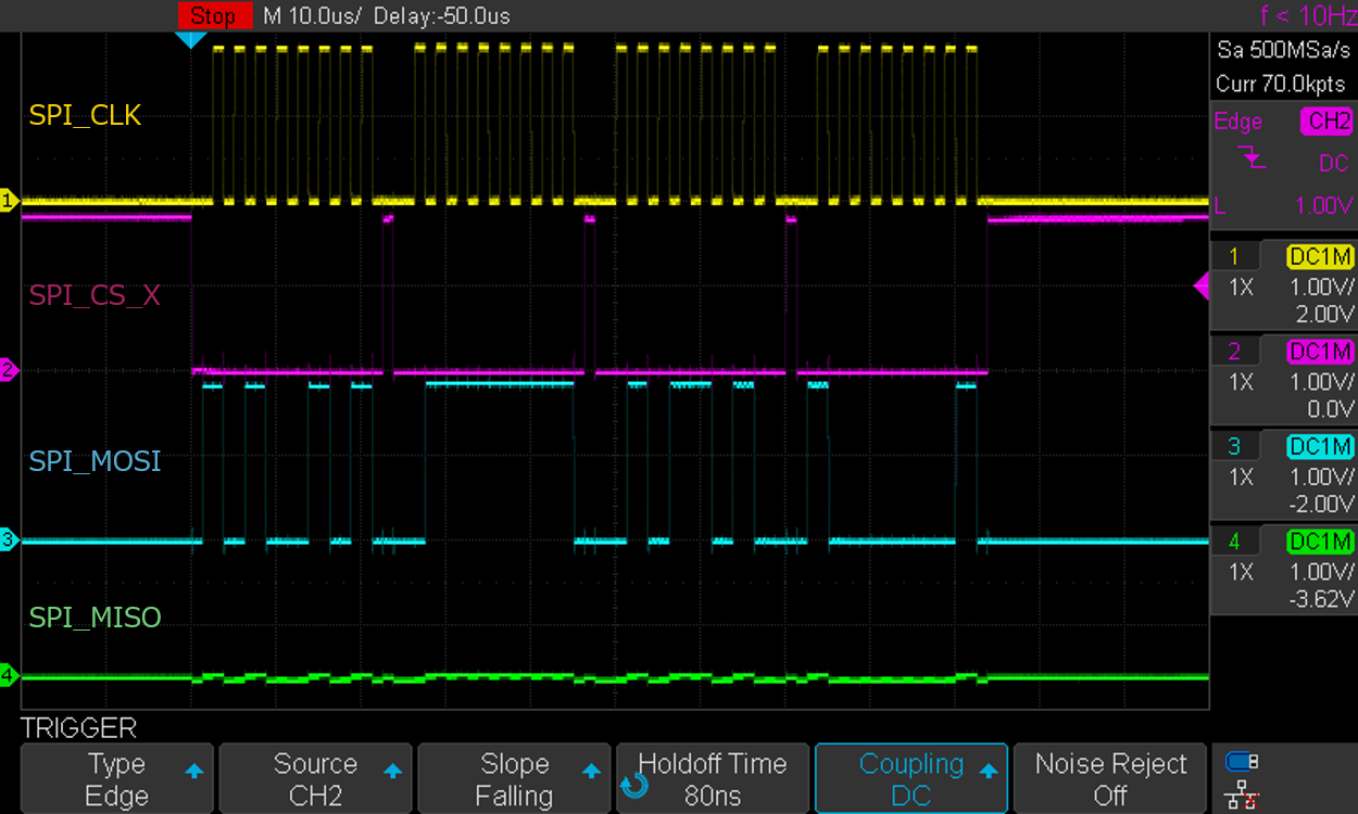
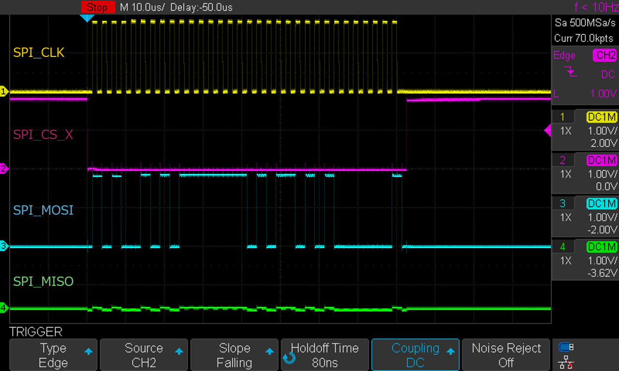
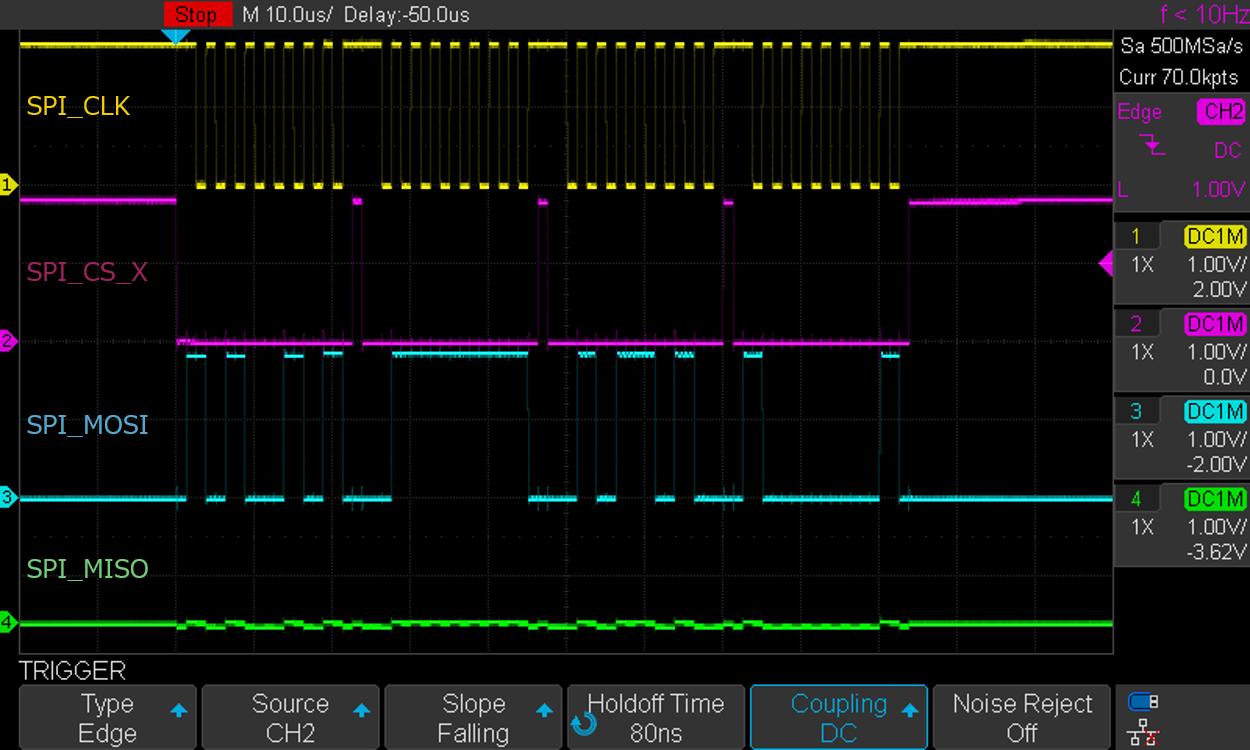
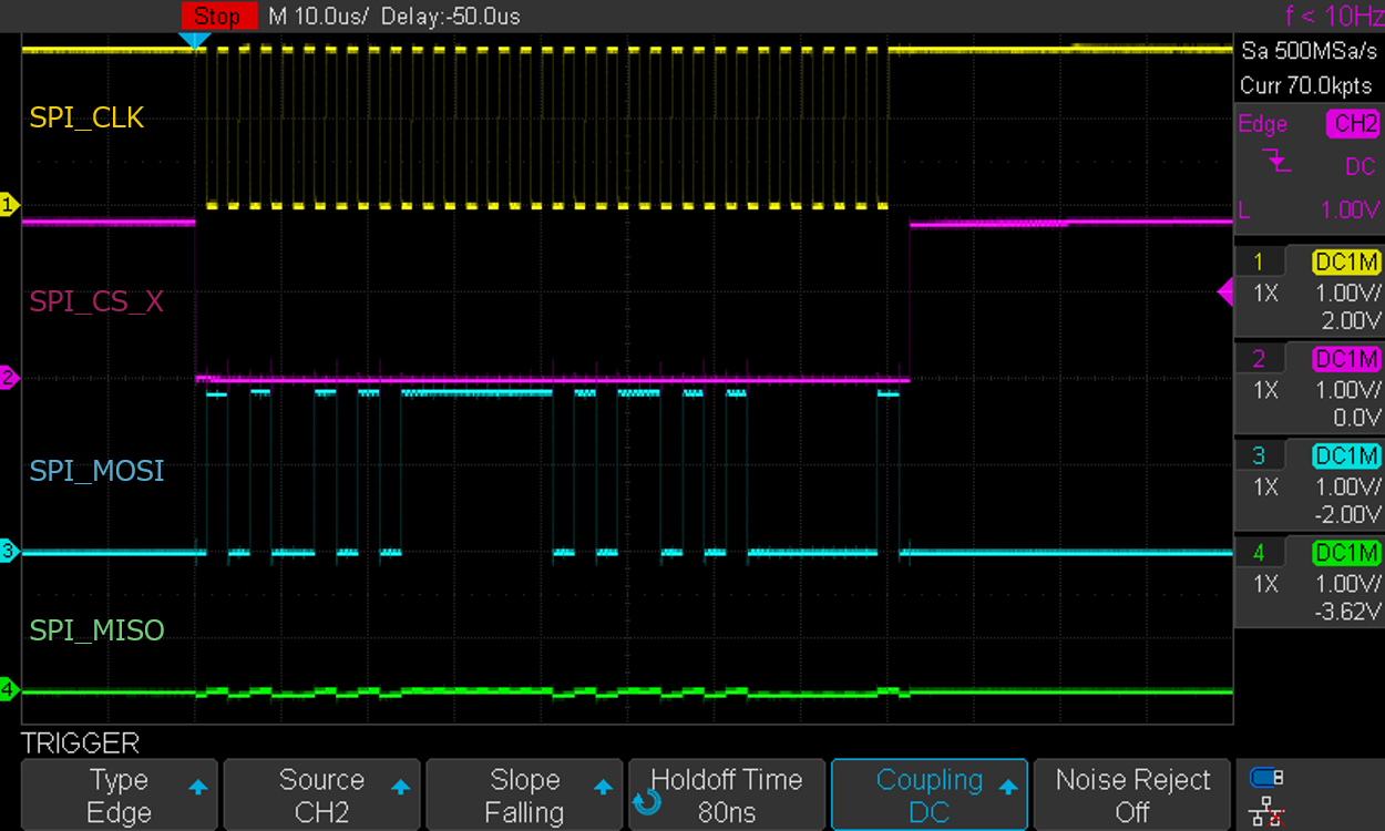
2.19. Storage Library
2.19.1. Overview
The Storage library defines a base class for various storage libraries as SDHCI, Flash and eMMC.
Basically, it is referred from SDHCI, Flash, eMMC libraries for each device. But you can also use the Storage library directly by specifying an absolute filename including the mount path.
The relationship between various storages and mount path is shown below for reference.
| Device | Mount Path |
|---|---|
SD card |
/mnt/sd0 |
Flash |
/mnt/spif |
eMMC |
/mnt/emmc |
2.19.2. Functions
See API references Storage Library API for the details.
| Function | Description |
|---|---|
Storage.open() |
Opens a file with the absolute path on the storage device. When the file is opened for writing, it will be created if it doesn’t exist yet. |
Storage.exists() |
Tests whether a file or directory exists on the storage device. |
Storage.mkdir() |
Create a directory on the storage device. |
Storage.rmdir() |
Remove a directory from the storage device.. |
Storage.remove() |
Remove a file from the storage device. |
2.20. Watchdog Library
The Spresense Watchdog library can trigger HW reset by using HW watchdog when system malfunctions from some use cases.
This library contains these functions:
-
Set the time until HW reset is executed
-
Acquire the time to reset
-
Reset time to reset
For example, you can use this library If you want to trigger HW reset, when the time that is enough for finishing all the processes expires in the loop() function.
2.20.1. How to use
Follow these steps to use this Library, also use Watchdog for WatchdogClass instance.
-
Initialize a watchdog by using
Watchdog.begin() -
Start to monitor by using
Watchdog.start(time)You need to set
time(ms) ⇐ 40000 for timer to trigger HW reset. -
Reset timer by using
Watchdog.kick()notify the system to keep-alive.If program is working fine, please execute
kick()to notify the system to keep-alive. -
When it is not necessary to monitor by Watchdog, please execute
Watchdog.stop()If you do not call
Watchdog.stop()orWatchdog.kick(), watchdog timer will expire and will trigger HW reset.
If you want to check the time remaining for trigger HW reset, you can use Watchdog.timeleft().
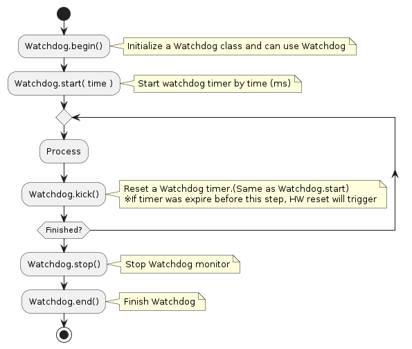
Watchdog timer will be reset when clock mode change by Section 2.9 or insert a SD card.
|
2.21. Wire Library
The Wire library allows Spresense to communicate with I2C / TWI devices.
The Wire library is used the same way as the Arduino Wire Library described in the Arduino language reference and is compatible with the examples given on that page.
The pins allocated to Wire are shown below.
| Wire instance | connector | SCL | SDA | IO voltage |
|---|---|---|---|---|
Wire |
main board |
D15 |
D14 |
1.8V |
Wire |
extension board |
D15 |
D14 |
3.3V or 5V (Jumper switch JP1) |
Wire1 |
extension board |
D09 |
D03 |
3.3V or 5V (Jumper switch JP1) |
Wire1 |
LTE extension board |
D09 |
D03 |
3.3V or 5V (Jumper switch CN2) |
The extension board interface voltage is set by the IOREF jumper to 3.3 or 5V. This sets the interface voltage for I2C. The D14, D15 pins also appear on the main board. The interface voltage is then 1.8V along with all other GPIO on the main board.
I2C communication requires the use of pull-up resistors.
-
The Spresense extension board includes 1k Ohms pull-up resistors so no additional components are required.
-
The Spresense main board includes 4.7k Ohms pull-up resistors so no additional components are required.
2.21.1. Features and Limitations
The port supports communication at 2 speeds which are defined in the library.
-
#define TWI_FREQ_100KHZ (100000) // standard mode
-
#define TWI_FREQ_400KHZ (400000) // fast mode
The default is standard mode, 100kHz. To change the speed to 400kHz, use the setClock(TWI_FREQ_400KHZ) function.
The library supports two I2C address lengths.
-
#define TWI_ADDR_LEN_7_BIT (7)
-
#define TWI_ADDR_LEN_10_BIT (10)
The default is 7 bit.
Like the original Arduino Wire library this library implementation uses a 32 byte buffer, therefore any communication should be within this limit. Exceeding bytes in a single transmission will just be dropped.