There are a number of core modules built into CircuitPython and commonly used libraries available. This section will introduce you to some of these and show you an example of how to use each one.
Some examples require external components, such as switches or sensors. You’ll find wiring diagrams where applicable to show you how to wire up the necessary components to work with each example.
1. CircuitPython Digital In & Out
This example shows how to use digital input and output.
The digitalio module contains classes to provide access to basic digital IO.
In this example, you can use a button as the input to control a digital output - a green LED on your Spresense board.
Copy and paste the following code into code.py using your editor:
import time
import board
from digitalio import DigitalInOut, Direction, Pull

led = DigitalInOut(board.LED0)
led.direction = Direction.OUTPUT

switch = DigitalInOut(board.D2)
switch.direction = Direction.INPUT
switch.pull = Pull.UP

while True:
    # We could also do "led.value = not switch.value"!
    if switch.value:
        led.value = False
    else:
        led.value = True

    time.sleep(0.01)  # debounce delay
The if/else block could be replaced with a simple led.value = not switch.value but we wanted to make it really clear how to test the inputs.
The interpreter will read the digital input when it evaluates switch.value.
|
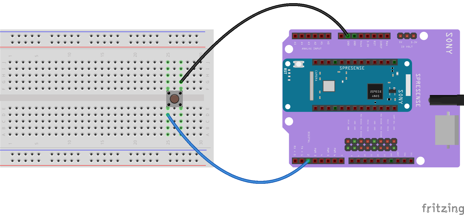
Wire a button between D2 and one of the two GND terminals on your Spresense extension board.
The button should be a switch with a built-in pullup resistor.
Press and hold the button to turn LED0 on.
1.1. Spresense GPIO
The digital signal pins available on Spresense hardware are:
-
On the main board
-
Pins
D0,D1, andD14-D28 -
Voltage 1.8V
-
-
On the extension board
-
Pins
D0-D15 -
Voltage 3.3V or 5V
Set the operating voltage by changing the position of the jumper on JP1, see Setting the operating voltage of the GPIO pin sockets on the extension board.
-
| Learn more about the Spresense pin names in CircuitPython from Spresense Hardware Overview for CircuitPython. |
1.2. More information
Learn more about the digitalio module in Read the Docs: Basic digital pin support.
2. CircuitPython Analog In
This tutorial shows how to read the analog voltage on an analog input pin on Spresense.
The analogio module contains class to provide access to analog IO, such as for analog-to-digital converter (ADC).
The Spresense extension board has six analog input channels and the main board has two analog input channels on dedicated pins.
Two of the Spresense analog channels are high speed with anti-aliasing pins - High Performance A/D Converter (HPADC): A4 and A5.
All other pins A0 - A3 are Low-power A/D Converter (LPADC).
The sampling frequencies, and voltages used by the pins are as follows:
| Pin no. | Type | Frequency (Hz) | Main board input voltage (V) | Extension board input voltage (V) |
|---|---|---|---|---|
|
LPADC |
64 |
- |
0 - 5 |
|
LPADC |
64 |
- |
0 - 5 |
|
LPADC |
64 |
0 - 0.7 |
0 - 5 |
|
LPADC |
64 |
0 - 0.7 |
0 - 5 |
|
HPADC |
16k |
- |
0 - 5 |
|
HPADC |
16k |
- |
0 - 5 |
For further details on ADC sampling frequencies in Spresense, see: ADC Sampling Frequency
For further details on using A/D converter with Spresense, see: How to Guides: How to use the A/D converter
Because CircuitPython requires using the extension board, only the extension board signal pins will work (they are exclusive).
This means A2 and A3 on the main board cannot be used.
|
For this example, we will read the analog voltage on A1.
Copy and paste the following code into code.py using your editor:
import time
import board
from analogio import AnalogIn

analog_in = AnalogIn(board.A1)

def get_voltage(pin):
    return (pin.value * 5) / 65536

while True:
    print((get_voltage(analog_in),))
    time.sleep(0.1)
2.1. Code description
- Creating the analog input
-
analog_in = AnalogIn(board.A1)Creates an object and connects the object to
A1as an analog input. -
get_voltage()helper -
getVoltage(pin)is our helper function. By default, analog readings range from 0 (minimum) to 65535 (maximum). This helper converts the 0 to 65535 reading frompin.valueto a 5V voltage value. - Main loop
-
The main loop is simple. It will
printout the voltage as floating point values by callingget_voltage()on our analog object. Connect to the serial console to see the results.
2.2. Adding a potentiometer
By default, the pins are floating so the voltages will vary.
With the serial console connected, try touching a wire from A1 to the GND pin or Vout pin to see the voltage change.
Add a potentiometer to control the voltage changes.
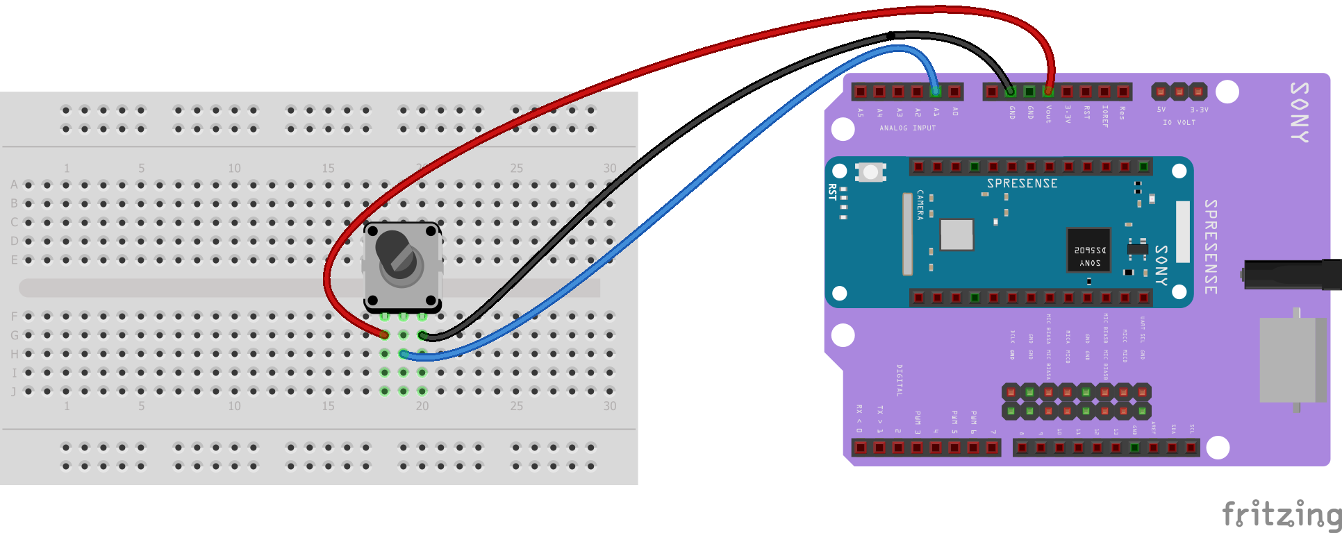
From the potentiometer to the board, connect the left pin to ground, the middle pin to A1, and the right pin to Vout.
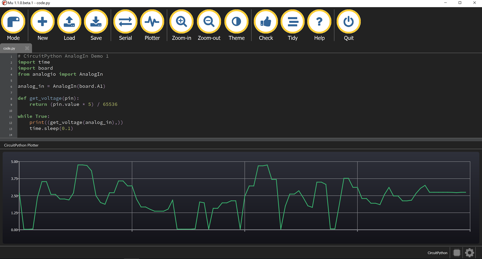
In your editor (we use Mu editor, here), you can see how the voltage changes on the plotter as you rotate the potentiometer, as shown in the screenshot below.
(Click the Plotter icon at the top of the window to open the plotter.)
When you turn the knob of the potentiometer, the wiper rotates left and right, increasing or decreasing the resistance.
This, in turn, changes the analog voltage level that will be read by your board on A1.
|
2.3. Read analog pin values into your code
The get_voltage() helper used in the potentiometer example above, reads the raw analog pin value and converts it to a voltage level.
You can, instead, read an analog pin value directly in your code using pin.value.
In the following sample code, the raw analog pin value is read from the potentiometer.
Copy and paste the following code into code.py using your editor:
import time
import board
from analogio import AnalogIn

analog_in = AnalogIn(board.A1)

while True:
    print(analog_in.value)
    time.sleep(0.1)
This works with any analog pin. Use the <pin_name>.value to read the raw value and use it in your code.
| Learn more about the Spresense pin names in CircuitPython from Spresense Hardware Overview for CircuitPython. |
2.4. More information
Learn more about the analogio module in Read the Docs: Analog hardware support.
3. CircuitPython I2C
I2C is a 2-wire protocol for communicating with simple sensors and devices, meaning it uses two connections for transmitting and receiving data.
I2C, which stands for inter-integrated circuit, is a serial protocol for devices to communicate with one another. It is called a serial protocol because it has a clock line and a single data line which is used for both sending and receiving data.
The I2C protocol uses two wires to send and receive data: a clock line (called SCL) and a data line (called SDA). The clock line pulses high and low to drive the sending and receiving of bits. The data line contains the value of a sent or received bit during clock line transitions.
The main board and extension board use the same system for I2C. They can be connected to several I2C devices at the same time if the devices have different addresses.
This tutorial shows how to scan the I2C bus for any connected device. Then we will show how to interact with an I2C device.
3.1. Spresense I2C
Spresense has a single I2C interface shared between main board and extension board. The interface voltage is 1.8V on the main board, and 5V or 3.3V on the extension board.
The I2C interface available on Spresense is:
-
On the main board
-
Pins
D14forSDAandD15forSCL -
Voltage 1.8V
-
-
On the extension board
-
Pins
D14forSDAandD15forSCL -
Voltage 3.3V or 5V
Set the operating voltage by changing the position of the jumper on JP1, see Setting the operating voltage of the GPIO pin sockets on the extension board.
-
| Although there are I2C pins on the main and extension boards, when the extension board is connected you cannot use the I2C pins on the main board. |
Learn more about the Spresense pin names in CircuitPython from Spresense Hardware Overview for CircuitPython.
For further details on using I2C with Spresense, see: How to Guides: How to use the I2C
3.2. Adding an I2C temperature sensor
To demonstrate interacting with an I2C device this guide will show you how to query the temperature from a MCP9808 high precision temperature sensor.
3.2.1. Wiring diagram
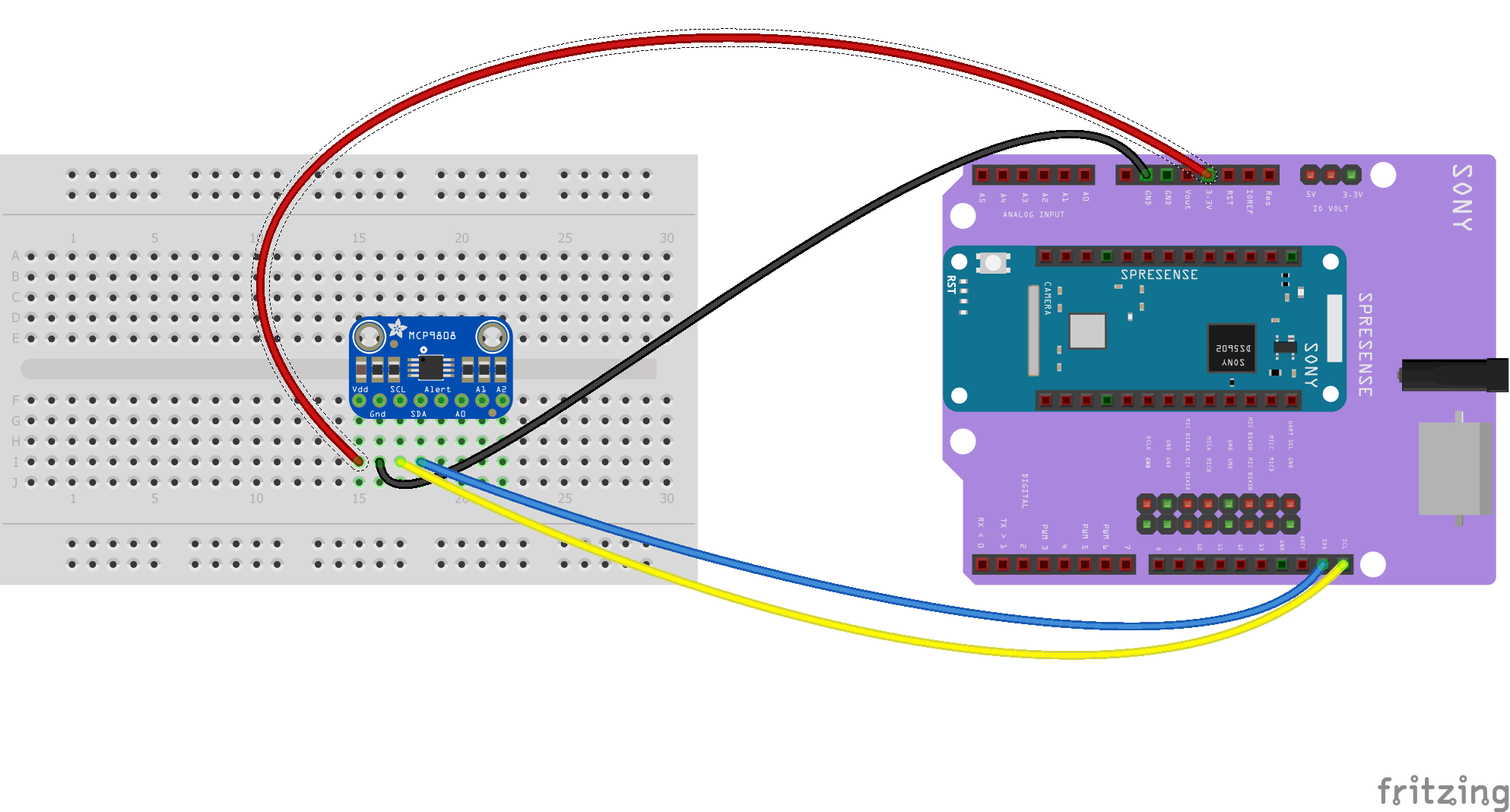
Use this wiring diagram to help find the correct pins and wire up the sensor. In this example, the MCP9808 sensor requires 3.3V or 5V, so we are using the I2C pins on the extension board.
-
GNDon the MCP9808 connect toGNDon the Spresense extension board. -
Vdd: connect to3.3V. -
SCL: connect toSCL(D15). -
SDA: connect toSDA(D14).
3.2.2. Checking sensor connection
Now we need to make sure that the I2C sensor is wired correctly. We perform a scan to see if the board is detected, and if it is, print out its I2C address.
Copy and paste the following code into code.py using your editor:
# If you run this and it seems to hang, try manually
# unlocking your I2C bus from the REPL with
#  >>> import board
#  >>> board.I2C().unlock()

import busio
import board
import time

i2c = busio.I2C(board.SCL, board.SDA)

while not i2c.try_lock():
    pass

try:
    while True:
        print("I2C addresses found:", [hex(device_address)
              for device_address in i2c.scan()])
        time.sleep(2)

finally:  # unlock the i2c bus when ctrl-c'ing out of the loop
    i2c.unlock()
Open the serial console to see the results.
The code prints out an array of addresses.
We’ve connected the MCP9808 which has a 7-bit I2C address of 0x18.
The result for this sensor is I2C addresses found: ['0x18'].
If no addresses are returned, refer back to the wiring diagrams to make sure you’ve wired up your sensor correctly.
3.2.3. I2C sensor data
Now we know our sensor is connected and ready to go, we can get the data from our sensor.
Copy and paste the following code into code.py using your editor:
import busio
import board
import time

# Decode the temperature
def temp_c(data):
    value = data[0] << 8 | data[1]
    temp = (value & 0xFFF) / 16.0
    if value & 0x1000:
        temp -= 256.0
    return temp

i2c = busio.I2C(board.SCL, board.SDA)

# Lock the I2C device before we try to read temperature
while not i2c.try_lock():
    pass

try:
    while True:
        result = bytearray(2)
        # write bytes of data from the board to the MCP9808 and
        # receive two bytes of temperature sensor register data
        i2c.writeto_then_readfrom(0x18, bytes([0x05]), result)
        # print decoded temperature
        print("Temperature:", temp_c(result))
        time.sleep(1.0)

finally:  # unlock the i2c bus when ctrl-c'ing out of the loop
    i2c.unlock()
3.2.4. Code description
The busio module contains an interface for using hardware-driven I2C communication from the Spresense board.
You can see in the section before the while-loop, we use the busio.I2C class from the busio module to create an interface to access the I2C bus.
When creating the I2C object you must specify the clock line and data line pins.
Spresense uses the board.SCL and board.SDA objects.
We create the i2c object, using busio.I2C using the default pins board.SCL and board.SDA.
Before doing the reads and writes, you must lock the I2C bus to make sure your code has exclusive access to I2C.
To do this we include a loop that waits until I2C is locked and then continues on to the scan function.
We have used i2c.try_lock() and i2c.unlock() at the end.
The lock uses a special loop syntax (while not… pass) that waits for the i2c.try_lock() function until it returns True.
Locking the bus tells CircuitPython that your code needs to use I2C and that any other code using I2C should wait for your code to finish.
In the main part of the loop we use i2c.writeto_then_readfrom() to receive two bytes of data from the sensor and the print the decoded temperature.
3.3. More information
Learn more about the busio.I2C class in Read the Docs: busio.I2C class.
4. CircuitPython SPI
SPI protocol is a serial protocol for transmission of data between two devices.
The protocol, which stands for Serial Peripheral Interface, is different to the I2C serial protocol in a number of ways:
-
SPI requires more connecting wires than I2C. SPI has explicit data input and data output wires instead of a single data wire used by I2C.
-
Multiple SPI devices can be connected to the same SPI bus, but each device requires its own Chip Select (CS) line to listen for SPI traffic, although they can share MOSI, MISO, and clock connections.
-
In contrast to I2C, SPI has no acknowledgment of data transmission, unless specifically built into particular SPI devices.
-
Where I2C uses a clock wire, SPI can use any speed in a range that goes from a few kHz up to hundreds of MHz. This means the SPI protocol can be used to send screen images to TFT displays, for example, because control of the clock speed allows it to quickly transmit large amounts of data.
This tutorial shows how to query the temperature from a MAX31855 thermocouple temperature sensor.
4.1. Spresense SPI
The Spresense main board and extension board both have SPI interfaces.
The SPI interfaces available on Spresense are:
-
On the main board
-
Pins
D23for SCK,D24for CS,D16for MOSI, andD17for MISO. -
Voltage 1.8V
-
-
On the extension board
-
Pins
D13for SCK,D10for CS,D11for MOSI, andD12for MISO. -
Voltage 3.3V or 5V
Set the operating voltage by changing the position of the jumper on JP1, see Setting the operating voltage of the GPIO pin sockets on the extension board.
-
| Spresense has SPI pins on the main and extension boards. Both can be used independently. |
Learn more about the Spresense pin names in CircuitPython from Spresense Hardware Overview for CircuitPython.
For further details on using SPI with Spresense, see: How to Guides: How to use the SPI
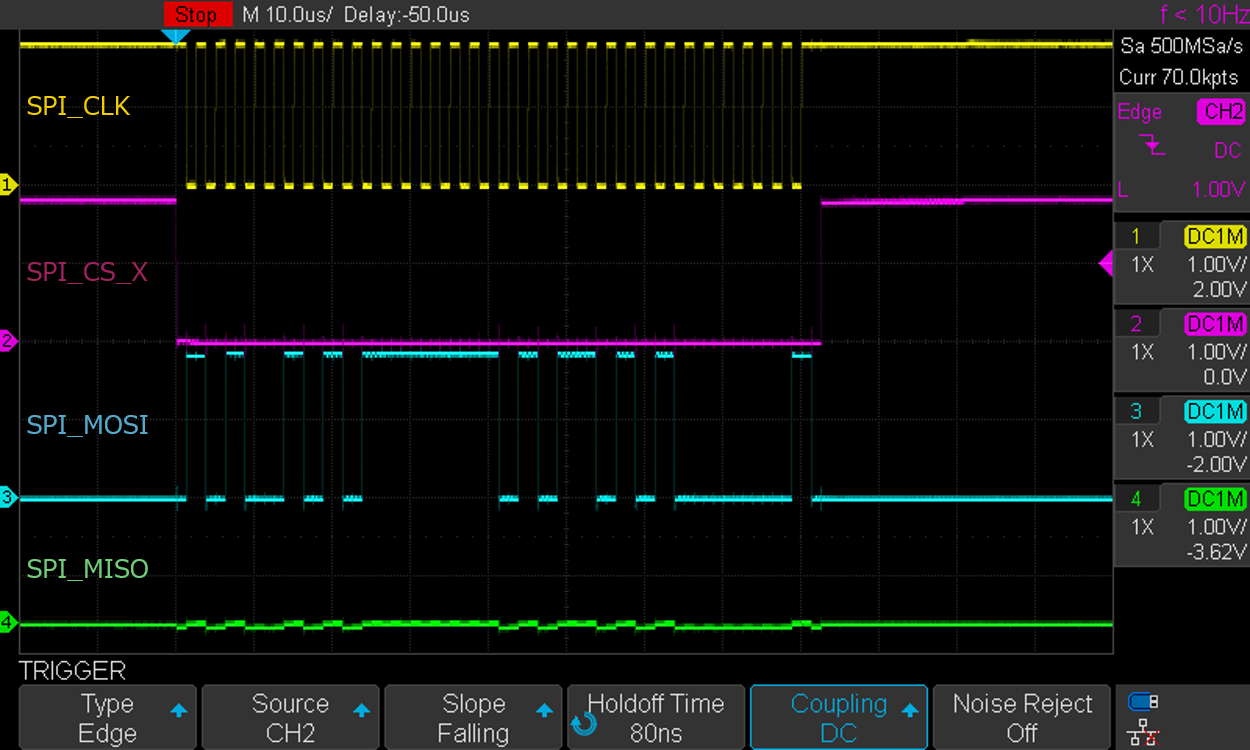
4.2. Spresense Chip Select (CS)
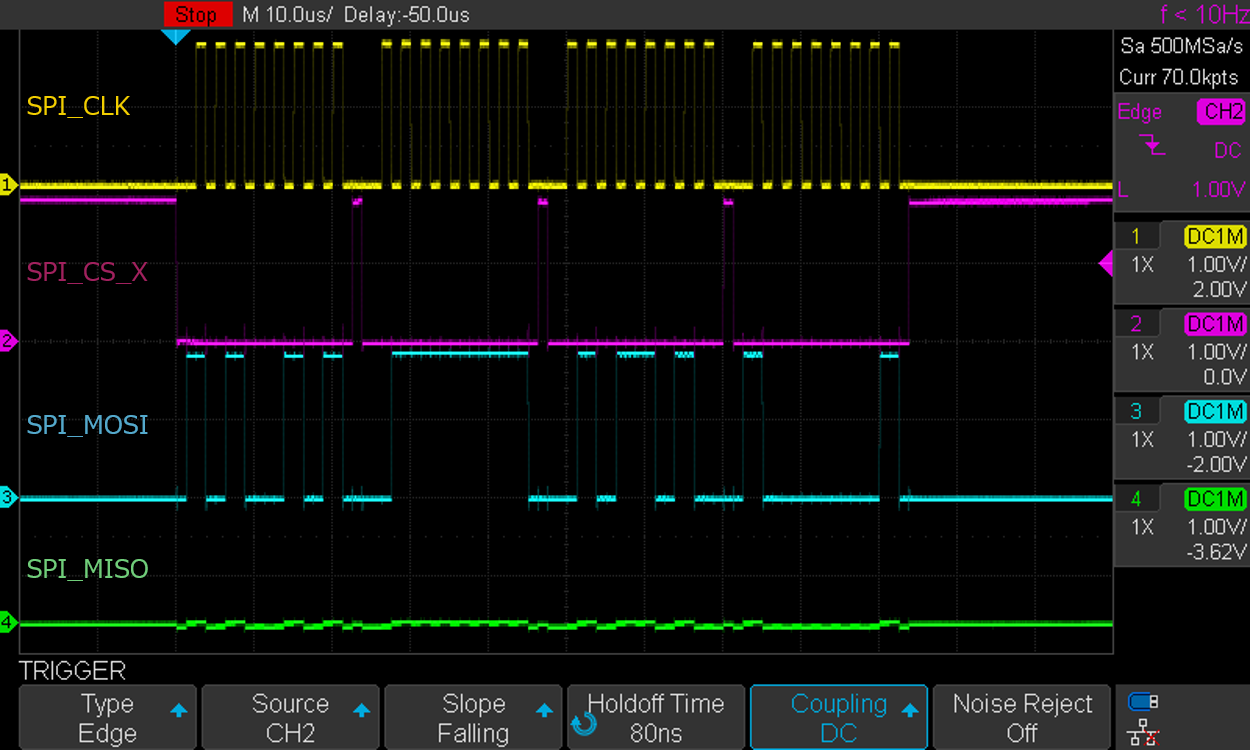
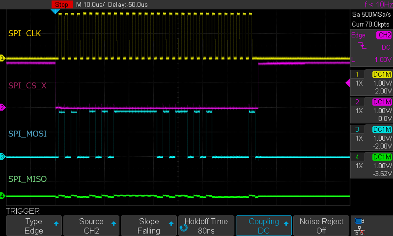
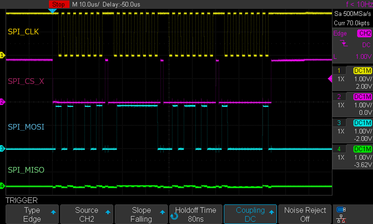
Spresense SPI CS automatically goes low at the start of each transaction and high at the end of each transaction.
This make coding easier and is useful for high speed data transfer.
If this does not suit your application, or you want to use multiple SPI devices use a different pin for CS and control it using DigitalInOut.
The behavior of CS is different depending on the phase and polarity. (purple: SPI_CS_X signal in below figure).
When phase=0, CS returns to HIGH for each word transferred.
Whereas, when phase=1, CS is set to LOW for the duration of data transfer.
| phase=0, polarity=0 | phase=1, polarity=0 |
|---|---|
|
|
| phase=0, polarity=1 | phase=1, polarity=1 |
|---|---|
|
|
4.3. Adding a thermocouple temperature sensor
This tutorial uses a simple SPI sensor, the MAX31855 thermocouple temperature sensor is an SPI device with a simple interface that uses a MISO line to read temperature data.
There are no registers or other complex structures to configure or process.
4.3.1. Wiring diagram
Use this wiring diagram to help find the correct pins and wire up the sensor. The MAX31855 can use 3.3V or 5V. In this example we are using the 3.3V pin.
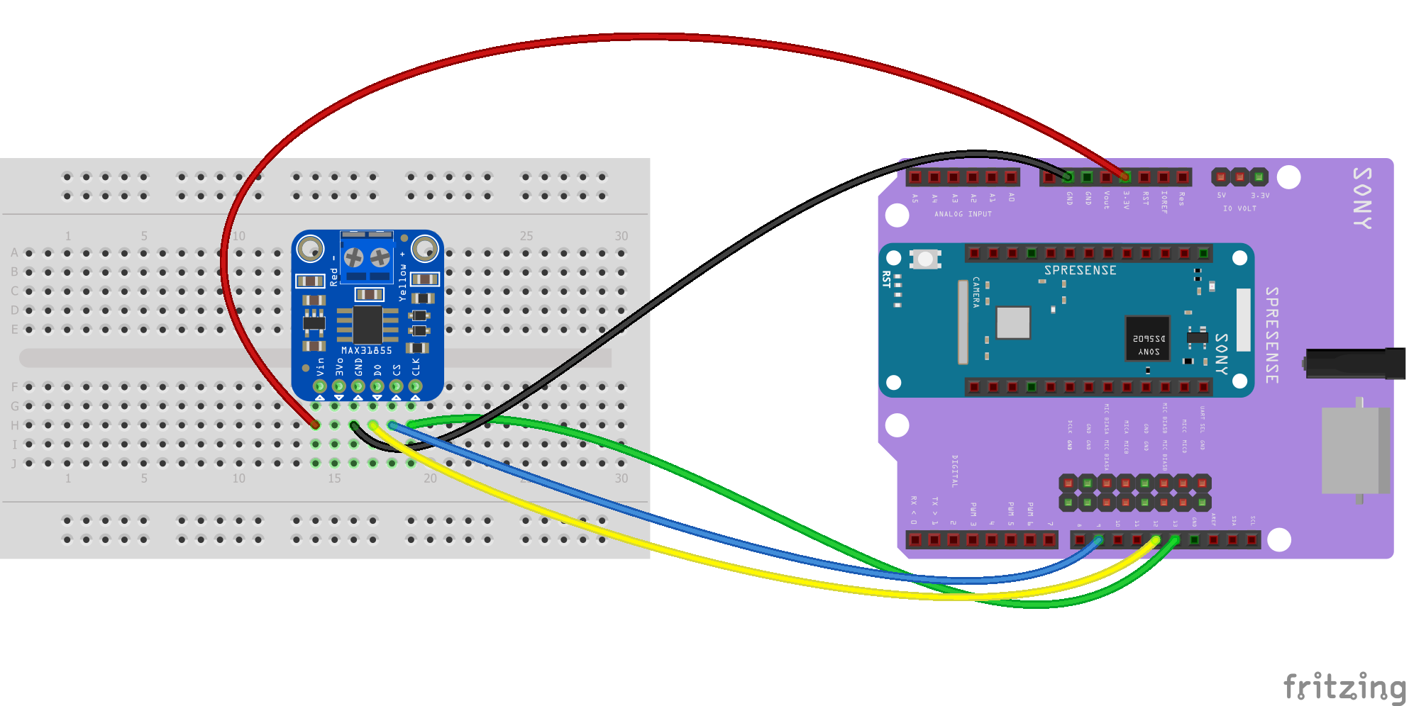
-
GNDon the MAX31855 connect toGNDon the Spresense extension board. -
VIN: connect to3.3V. -
D0: connect toMISO(D12). -
CLK: connect toSCK(D13). -
CS: connect toD9.
This wiring will configure hardware-based SPI communication to use Spresense’s built-in SPI communication hardware.
4.3.2. SPI sensor data
Copy and paste the following code into code.py using your editor:
import busio
import board
import time
import digitalio

# Decode the temperature
def temp_c(data):
    temp = data[0] << 8 | data[1]
    if temp & 0x0001:
        return float('NaN')  # Fault reading data.
    temp >>= 2
    if temp & 0x2000:
        temp -= 16384  # Sign bit set, take 2's compliment.
    return temp * 0.25

cs = digitalio.DigitalInOut(board.D9)
cs.direction = digitalio.Direction.OUTPUT
cs.value = True

spi = busio.SPI(board.SCK, MISO=board.MISO)

# try.lock locks the SPI bus so we can access the sensor
# for our sole use
while not spi.try_lock():
    pass

spi.configure(baudrate=5000000, phase=0, polarity=0)

try:
    while True:
        cs.value = False
        result = bytearray(4)
        spi.readinto(result)
        cs.value = True
        print("Temperature:", temp_c(result))
        time.sleep(1.0)

finally:  # unlock the spi bus when ctrl-c'ing out of the loop
    spi.unlock()
4.3.3. Code description
First, we import the board and busio modules, and digitalio module to control the CS line.
Then we set up to decode the temperature from the sensor.
We need a digital output to drive the CS line.
This is done with the lines beginning: cs = digitalio.DigitalInOut(board.D9).
These go on to set up CS to be high cs.value=True when not in use and pulled low when we are talking to it (in the main loop).
Next we create an interface to the SPI hardware bus with the line to create an instance of the busio.SPI class.
To create the SPI object you must pass a clock pin and at least one data pin (MISO or MOSI).
The MAX31855 doesn’t use the MOSI pin, so we only provide MISO.
You must lock the SPI bus to make sure your code has exclusive access to SPI.
We have used spi.try_lock() and spi.unlock() at the end.
The spi.configure() call sets the baudrate, phase, and polarity.
It must always be configured after locking the bus and before talking to your device because another device might have changed these.
The parameters are chosen for the MAX31855 device.
Outside the main loop, we set up to lock the SPI bus.
The lock uses a special loop syntax (while not… pass) that waits for the spi.try_lock() function until it returns True.
When the SPI bus is locked, we can then transfer data.
In the main loop, the CS line is toggled down to a low logic level. Remember with SPI, each device needs a chip select line to tell it when it’s ready to send and receive data.
We use spi.readinto to get the data from the sensor and print it, using temp_c() to decode the result and translate it to degrees Centigrade.
Lastly, the CS line is toggled back to a high digital logic level. This tells the MAX31855 we have finished talking to it and it can stop listening or sending data.
4.4. More information
Learn more about the busio.SPI class in Read the Docs: busio.SPI class.
5. CircuitPython UART
The Spresense main and extension boards both have UART serial pins you can use. They can be used to talk to UART devices such as sensors and other microcontrollers.
The example here shows how you can connect the US-100 ultrasonic sensor to Spresense and communicate through UART.
5.1. Using UART with Spresense
The Spresense main board and extension board both have UART pins.
The UART interface available on Spresense is:
-
On the main board
-
Pins
D0for RX,D1for TX,D27for CTS, andD28for RTS. -
Voltage 1.8V
-
-
On the extension board
-
Pins
D0for RX,D1for TX. -
Voltage 3.3V or 5V
Set the operating voltage by changing the position of the jumper on JP1, see Setting the operating voltage of the GPIO pin sockets on the extension board.
-
| You cannot use the UART on both the main board and the extension board at the same time. |
The extension board is configured to have the UART enabled when it is shipped. To use the UART pins on the main board when attached to the extension board, connect a 2.54mm pitch jumper to pin 1 and 2 on JP10 of the extension board to disable the extension board UART. No jumper is supplied with the Spresense boards so this has to be purchased separately.
When the extension board UART is activated, the UART pins (D0, D1, D27 and D28) of the main board cannot be used for GPIO.
Learn more about the Spresense pin names in CircuitPython from Spresense Hardware Overview for CircuitPython.
For further details on using UART with Spresense, see: How to Guides: How to use the UART
5.2. Adding an ultrasonic UART device to Spresense
You will need the following components:
-
US-100 ultrasonic distance sensor from Adafruit.
-
Pitch jumper
5.2.1. Wiring diagram
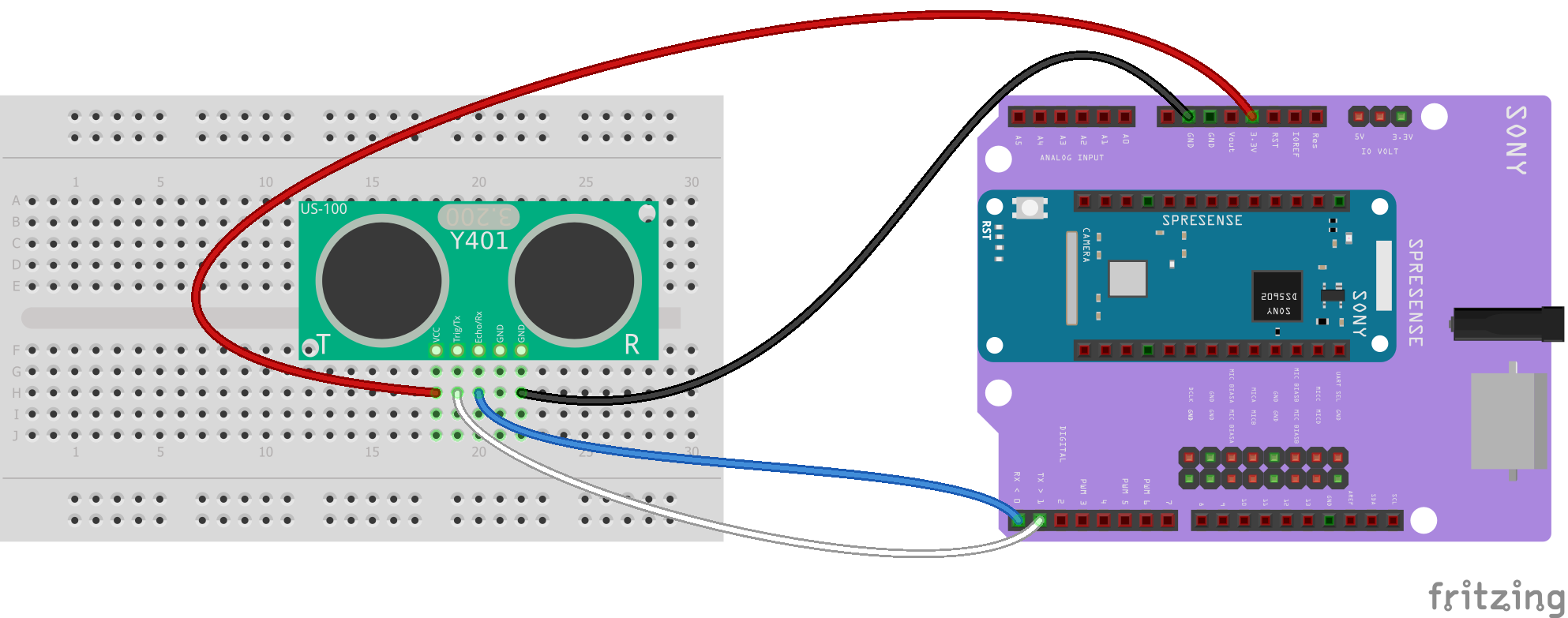
-
GNDon the US-100 connect toGNDon the Spresense extension board. -
VCC: connect to3.3V. -
Trig/TX: connect toTX(D1). -
Echo/RX: connect toRX(D0). -
The jumper must be present on the back of the sensor board.
| Usually, with UART-serial, you connect RX on one board to TX on the other. However, in this case, you need to connect TX-TX and RX-RX. |
5.2.2. Sample code
Copy and paste the following code into code.py using your editor:
import busio
import board
import time

uart = busio.UART(board.TX, board.RX, baudrate=9600)

while True:
    uart.write(bytes([0x55]))
    time.sleep(0.1)
    data = uart.read(2)  # 2 byte return for distance.
    if data:
        dist = (data[1] + (data[0] << 8)) / 10
        print("Distance: ", dist)
    time.sleep(0.5)
5.2.3. Code description
First, we create the uart object for the data from the US-100 device.
We provide the pins we’d like to use, board.TX and board.RX, and we set the baudrate=9600.
The basis of the while loop is obtaining the data needed to calculate the distance from the device.
If data exists, calculate the distance using the formula for the dist and by reading the 2 bytes returned.
Output the result using print().
Last, sleep() for 0.5 s.
5.3. More information
Learn more about the busio.UART class in Read the Docs: busio.UART class.
6. CircuitPython PWM
The two examples here show how to use PWM with Spresense.
The pwmio module contains classes to provide access to PWM.
Spresense has 4 PWM channels and supports voltages of 5V, 3.3V and 1.8V, allowing you to control a wide range of devices by PWM, such as: LEDs, control servos, beep piezos. You can also use Spresense to manage "pulse train"-type devices.
6.1. Example PWM with fixed frequency
This example shows how to use PWM to fade a small LED connected to your Spresense board.
Copy and paste the following code into code.py using your editor:
import time
import board
import pwmio

# On the Spresense extension board:
# PWM0 is designated D6, PWM1 is D5, PWM2 is D9, PWM3 is D3
# LED setup for Spresense using pin PWM0:
led = pwmio.PWMOut(board.D6, frequency=5000, duty_cycle=0)

while True:
    for i in range(100):
        # PWM LED up and down
        if i < 50:
            led.duty_cycle = int(i * 2 * 65535 / 100)  # Up
        else:
            led.duty_cycle = 65535 - int((i - 50) * 2 * 65535 / 100)  # Down
time.sleep(0.01)- Main Loop
-
The main loop uses
range()to cycle through the loop. When the range is below 50, the PWM increases the LED brightness, and when the range is above 50, the PWM dims the LED.The
time.sleep()is needed to allow the PWM process to control the rate of increasing/decreasing brightness, otherwise it would be too quick for you to notice. - Creating the PWM output
-
led = pwmio.PWMOut(board.D6, frequency=5000, duty_cycle=0)Creates an object
led, and usespwmio.PWMOutto create the output and pass in theD6pin to use.
6.2. PWM output with varying frequency
Following on from the fixed frequency example, this example shows how to vary the frequency using pwmio to produce a series of tones through a piezo.
Copy the following code into code.py using your editor.
As you can see, it is simpler than the fixed frequency example.
import time
import board
import pwmio

# Piezo setup for Spresense using pin PWM0:
piezo = pwmio.PWMOut(board.D6, duty_cycle=0, frequency=440, variable_frequency=True)

while True:
    for f in (262, 294, 330, 349, 392, 440, 494, 523):
        piezo.frequency = f
        piezo.duty_cycle = 65535 // 2  # On 50%
        time.sleep(0.25)  # On for 1/4 second
        piezo.duty_cycle = 0  # Off
        time.sleep(0.05)  # Pause between notes
time.sleep(0.5)6.3. Spresense PWM
The digital signal pins available on Spresense hardware are:
-
On the extension board
-
Pins
D6,D5,D9, andD3 -
Voltage 3.3V or 5V
Set the operating voltage by changing the position of the jumper on JP1, see: Setting the operating voltage of the GPIO pin sockets on the extension board.
-
| Learn more about the Spresense pin names in CircuitPython from: Spresense Hardware Overview for CircuitPython. |
For further details on using PWM with Spresense, see: How to Guides: How to use the PWM
6.4. More information
Learn more about the pwmio module in Read the Docs: Support for PWM based protocols.
7. CircuitPython SD Card Tutorial
The Spresense extension board has a built-in SD card port that can be used for file storage. It has a 1.8V 4-bit (or 1-bit) SD mode interface compliant with the SDIO standard.
The maximum data transfer rate for Spresense’s SDIO is 21 MB/s.
This tutorial describes how to read and write data to an SD card on Spresense.
7.1. Reading and writing to SD cards on Spresense
7.1.1. Initializing the SD card into CircuitPython
The class sdioio.SDCard is used to control the SD card over SDIO, the parallel protocol designed for SD cards.
It uses a clock pin, a command pin, and 1 or 4 data pins.
It can be operated at a high frequency such as 25MHz.
Usually, an SDCard object is used with storage.VfsFat to allow file I/O to an SD card.
Typically you initialize the SD card as follows:
import board
import sdioio
import storage

sd = sdioio.SDCard(
    clock=board.SDIO_CLOCK,
    command=board.SDIO_COMMAND,
    data=board.SDIO_DATA,
    frequency=25000000)
vfs = storage.VfsFat(sd)
storage.mount(vfs, '/sd')
The sd object using the sdioio.SDCard class and sets up pins for clock, command, and data from the board container.
The frequency is set to 25 MHz.
The vfs object is set up as an SDCard object using the storage.VfsFat() function.
7.1.2. Writing to a file
CircuitPython and MicroPython is very close to desktop Python in the way it reads data from and writes to an SD card.
You use file operations like open, close, read, and write.
For example, to create a file and write the standard "Hello world! line of text to it you can run:
with open("/sd/test.txt", "w") as f:
    f.write("Hello world!\r\n")
The with statement is used to create a context manager that opens and automatically closes the file.
In Python, file access requires you close the file, otherwise you might lose any data.
The automatic close means you don’t have to remember to close the file.
The open function is used to open the file by passing the path /sd/test.txt and the mode (w for writing).
The file will be created on the SD card that was mounted as that path.
Inside the context manager you can access the f variable to operate on the file while it’s open.
The write function is called to write a line of text to the file.
You need to end the string passed to write with a carriage returns and new line, explicitly: \r\n.
7.1.3. Reading and printing from a file
Reading from a file works in a similar way to writing:
with open("/sd/test.txt", "r") as f:
    print("Read line from file:")
    print(f.readline())
You can use readline in a loop to read all lines from a file.
Printing stops when readline reaches the end of the file, when it will return an empty:
with open("/sd/test.txt", "r") as f:
    print("Printing lines in file:")
    line = f.readline()
    while line != '':
        print(line)
        line = f.readline()
The readlines function reads all of the lines in the file and returns them in an array of lines.
If the file is very large you might run out of memory, as the entire file must be loaded:
with open("/sd/test.txt", "r") as f:
    lines = f.readlines()
    print("Printing lines in file:")
    for line in lines:
        print(line)
7.1.4. Append data to a file
Appending data at the end at the end of a file works exactly the same as in Python.
You tell the open function to append using the a option instead of overwriting with new data (using the w option).
For example, try the following:
with open("/sd/test.txt", "a") as f:
    f.write("This is another line!\r\n")
7.2. More information
Learn more about the sdioio module in Read the Docs: sdioio - Interface to an SD card via the SDIO bus.
8. CircuitPython GNSS tutorial
The Spresense main board is equipped an ultra-low-power Global Navigation Satellite System (GNSS) receiver that calculates its current position, velocity and time. It can be used to acquire precise positioning for applications such as tracking devices and drones.
Spresense also includes a real-time clock which is great for data logging in association with the GNSS system.
As GNSS is a built-in feature in Spresense, it does not require any pin allocations. An antenna is also included on the Spresense main board.
If you want to attach an external antenna for higher position precision, please refer to: How to Guides: How to use the GNSS
8.1. Recording positioning data with the Spresense GNSS system
The CircuitPython module gnss is used to control the Spresense GNSS and acquire positioning information.
We use the class gnss.GNSS to acquire positioning information from GNSS.
8.1.1. Sample code
import gnss
import time

nav = gnss.GNSS([gnss.SatelliteSystem.GPS, gnss.SatelliteSystem.GLONASS])
last_print = time.monotonic()
while True:
    nav.update()
    current = time.monotonic()
    if current - last_print >= 1.0:
        last_print = current
        if nav.fix is gnss.PositionFix.INVALID:
            print("Waiting for fix...")
            continue
        print("Latitude: {0:.6f} degrees".format(nav.latitude))
        print("Longitude: {0:.6f} degrees".format(nav.longitude))
8.1.2. Code description
First, turn on the GNSS system to set up to get positioning information from two satellite systems: GPS and GLONASS.
nav = gnss.GNSS([gnss.SatelliteSystem.GPS, gnss.SatelliteSystem.GLONASS])
We will use the objects last_print and current to test the time difference between fixes, so that updates don’t happen too often.
In the main loop, we get the positioning update and current time:
while True:
    nav.update()
    current = time.monotonic()
    if current - last_print >= 1.0:
        last_print = current
If it is longer than 1 second between updates, update the current time and go on to get a positioning update.
Test if the positioning information is valid.
If so, use print() to output the latitude and longitude to nav in degrees.
Otherwise, output Waiting for fix….
8.2. More information
Learn more about the gnss.GNSS class in Read the Docs: gnss - Global Navigation Satellite System.
9. CircuitPython Camera tutorial
Spresense comes with a dedicated camera board that connects to the Spresense main board through a CMOS 8 bit parallel interface.
This tutorial describes how to take pictures with the Spresense camera and save them to an SD card.
You will need the following items:
-
Spresense camera, model number CXD5602PWBCAM1
-
Spresense camera connector cable
-
A microSD card
As with the other CircuitPython tutorials, you will also need the Spresense extension board.
9.1. Taking pictures with the Spresense camera
This example code sets up the Spresense camera to take pictures of size 1920x1080 pixels, in jpeg format and store them on the SD card on the Spresense extension board.
The CircuitPython module camera is used to control the camera and take pictures.
You will use the classes camera.Camera to control the camera and camera.ImageFormat to set the image format (for example jpeg).
You will also need to import the sdioio and storage modules as you will need to store the pictures on the SD card, controlled over SDIO.
import board
import sdioio
import storage
import camera
9.1.1. Set up the Spresense camera
Do the following:
-
Connect the Spresense camera board to the Spresense main board using the connector cable provided.
-
Insert the microSD card into the SD card port on the Spresense extension board.
9.1.2. Sample code
Copy and paste the following code into code.py using your editor:
import board
import sdioio
import storage
import camera

# Initialize SD card storage
sd = sdioio.SDCard(
    clock=board.SDIO_CLOCK,
    command=board.SDIO_COMMAND,
    data=board.SDIO_DATA,
    frequency=25000000)
vfs = storage.VfsFat(sd)
storage.mount(vfs, '/sd')

# Set up camera, assign picture attributes, and take picture
# Write picture data to file `buffer`.
cam = camera.Camera()

buffer = bytearray(512 * 1024)
file = open("/sd/image.jpg","wb")
size = cam.take_picture(buffer, width=1920, height=1080, format=camera.ImageFormat.JPG)
file.write(buffer, size)
file.close()
9.1.3. Code description
After import of the classes, the SD card and storage is set up. For details, see: CircuitPython SD Card Tutorial.
Then we set up the storage for the camera pictures, including the buffer for receiving the pictures, size, and format of pictures.
We end up with jpegs of size 1920 pixels by 1080, stored to buffer.
We use the two file commands to write to buffer on the SD card and then close it.
We don’t need an explicit open.
The format of the take_picture() function is:
take_picture(self, buf: _typing.WriteableBuffer, format: camera.ImageFormat), where:
-
buf, the writable buffer is assigned tobufferin theformatgiven bycamera.ImageFormat. -
Formatcan be given as:-
JPG.ImageFormatfor jpeg format -
RGB565:ImageFormatfor RGB-565 format
-
The size is given by width and height.
It returns the number of bytes written to buffer.
9.2. More information
Learn more about the camera.Camera class in Read the Docs: camera - Support for camera input.
10. Build and deploy CircuitPython on Spresense from sources
This tutorial describes how to build a system image from sources and then flash the bootloader and CircuitPython images to your Spresense board.
10.1. Set up your development environment for CircuitPython on Spresense
You can build and deploy CircuitPython to Spresense on a PC using Linux/Windows/Mac OS X. The development environment for each OS can be set up as follows:
| You also need a USB cable to connect Spresense and the PC. |
10.1.1. Setup for Linux
-
Serial Configuration
Add user to
dialoutgroupsudo usermod -a -G dialout <user-name>Please logout and login after running the above command.
-
Install the Spresense developer tools
wget https://raw.githubusercontent.com/sonydevworld/spresense/master/install-tools.sh
bash install-tools.sh
-
Activate the installed tools
source ~/spresenseenv/setupThis command must be run in every terminal window.
10.1.2. Setup for Windows
-
Install the USB serial driver
-
CP210x USB to serial driver (v11.1.0) for Windows 10/11
If you use the latest Silicon Labs driver (v11.2.0) in Windows 10/11 environment, USB communication may cause an error and it may fail to flash the program. Please download v11.1.0 from the above URL and install it.
-
-
Install the terminal application MSYS2
-
Install the Spresense developer tools
Run
MSYS2 MSYSfrom start menu, and run following commands.curl -L https://raw.githubusercontent.com/sonydevworld/spresense/master/install-tools.sh > install-tools.sh bash install-tools.sh
-
Activate the installed tools
source ~/spresenseenv/setupThis command must be run in every terminal window.
10.1.3. Setup for Mac OS X
-
Install the USB serial driver:
-
Open
Terminaland install the Xcode developer tools from Applexcode-select --install -
Install Python3
-
Install the Spresense developer tools
curl -L https://raw.githubusercontent.com/sonydevworld/spresense/master/install-tools.sh > install-tools.sh
bash install-tools.sh
-
Activate the installed tools
source ~/spresenseenv/setupThis command must be run in every terminal window.
10.2. Build CircuitPython for Spresense
-
Clone the CircuitPython repository using
git clone https://github.com/adafruit/circuitpython.git -
Change directory to circuitpython
cd circuitpython -
Pull all submodules into your clone using
git submodule update --init --recursive -
Build the MicroPython cross-compiler using
make -C mpy-cross -
Change directory to cxd56
cd ports/cxd56 -
Build the CircuitPython image for Spresense using
make BOARD=spresense
10.3. Connect the Spresense main board to the PC
-
Connect the Spresense main board to the PC using the USB cable, to power the main board and allow serial communication to flash the bootloader and CircuitPython image.

10.4. Flash the Spresense board bootloader
Flash the bootloader the first time you use Spresense.
| If you already flashed the bootloader to your Spresense board, you can skip ahead to Flash the CircuitPython image to Spresense. |
-
Download the Spresense binaries zip archive from Spresense firmware v2-0-002
-
Extract the Spresense binaries in your PC to
ports/cxd56/spresense-exported-sdk/firmware/ -
Flash the bootloader using
make BOARD=spresense flash-bootloader

