
1. Examples
The examples in the Spresense SDK are installed as a built-in command in the NuttShell environment. Refer to the README.txt file in the directory of each example for additional details about the required SDK configuration etc.
|
If you are building for the first time, please refer to the getting started guide. There are detailed instructions about how to configure and run the built program. |
2. Peripheral Driver Tutorials
2.1. RTC alarm example application
This section describes the usage of RTC alarm example application.
2.1.1. How to build
This is the build procedure via the command line.
When you use IDE, refer to the explanation of the following configuration.
-
Change directory to
sdkIf you do source
build-env.shscript, you can use the tab completion of theconfig.pytool.cd spresense/sdk source tools/build-env.sh
-
Kernel configuration and building
In this case, kernel configuration uses release-defconfig.
If you have already built the kernel, you can skip this step.tools/config.py --kernel release make buildkernel
-
SDK configuration and building
Execute the configuration by specifying
examples/alarmas an argument ofconfig.py.
If the build is successful, anuttx.spkfile will be created under thesdkdirectory.tools/config.py examples/alarm make
-
Flashing
nuttx.spkinto Spresense boardIn this case, the serial port is
/dev/ttyUSB0, and the baudrate of the uploading speed is500000bps. Please change according to your environment.tools/flash.sh -c /dev/ttyUSB0 -b 500000 nuttx.spk
2.1.2. Operation check
Open the serial terminal, and run alarm command.
-
Open the serial terminal
This is an example of using a minicom terminal with
/dev/ttyUSB0as the serial port and115200as the baudrate.minicom -D /dev/ttyUSB0 -b 115200 -
Type
alarmcommand on NuttShell promptThe usage of
alarmcommand is shown below.nsh> alarm ERROR: Invalid number of arguments: 0 USAGE: alarm <seconds> Where: <seconds> The number of seconds until the alarm expires.<seconds> means the relative time (seconds). For example,
alarm 5will trigger the RTC alarm after 5 seconds.nsh> alarm 5 alarm_daemon started alarm_daemon: Running Opening /dev/rtc0 Alarm 0 set in 5 seconds nsh> alarm_demon: alarm 0 received
2.1.3. RTC alarm with power saving features
Here is an example of using the alarm command in combination with the power saving features.
Spresense provides power saving features such as Deep Sleep and Cold Sleep modes.
It can enter these sleep states using the shutdown or poweroff command.
And, by the RTC alarm function, it can wake up from these sleep states.
For more information about Deep Sleep and Cold Sleep, refer to Sleep Mode.
The usage of shutdown and poweroff commands is shown below.
nsh> help shutdown
shutdown usage:  shutdown [--reboot]
nsh> help poweroff
poweroff usage:  poweroff [--cold]
2.1.3.1. Wake up from Deep Sleep mode
In the following example, an alarm is set after 10 seconds,
and the system enters Deep Sleep mode by shutdown command.
After 10 seconds, the alarm is expires and the system wakes up from the Deep Sleep state.
nsh> alarm 10
alarm_daemon started
alarm_daemon: Running
Opening /dev/rtc0
Alarm 0 set in 10 seconds
nsh> shutdown

NuttShell (NSH) NuttX-7.22
nsh>
2.1.3.2. Wake up from Cold Sleep mode
In the following example, an alarm is set after 10 seconds,
and the system enters Cold Sleep mode by poweroff --cold command.
After 10 seconds, the alarm is expires and the system wakes up from the Cold Sleep state.
nsh> alarm 10
alarm_daemon started
alarm_daemon: Running
Opening /dev/rtc0
Alarm 0 set in 10 seconds
nsh> poweroff --cold

NuttShell (NSH) NuttX-7.22
nsh>
2.1.4. Other RTC commands
The date command allows you to set the RTC time and display the current RTC time.
nsh> help date
date usage:  date [-s "MMM DD HH:MM:SS YYYY"]
e.g) set 2019/12/1 23:34:56 to RTC
nsh> date -s "Dec 1 23:34:56 2019"
The current time is displayed by the date command.
nsh> date
Dec 01 23:35:14 2019
The RTC time is kept during sleep modes such as Deep/Cold Sleep and rebooting by the reboot command.
However, if the power supply is turned off or the reset button is pressed, the RTC time will be clear.
The following example shows that the RTC time is retained even after the system reboot with the reboot command.
nsh> date
Dec 01 23:41:08 2019
nsh> reboot

NuttShell (NSH) NuttX-7.22
nsh> date
Dec 01 23:41:12 2019
nsh>
2.2. Watchdog example application
This section describes the usage of Watchdog example application.
2.2.1. How to build
This is the build procedure via the command line.
When you use IDE, refer to the explanation of the following configuration.
-
Change directory to
sdkIf you do source
build-env.shscript, you can use the tab completion of theconfig.pytool.cd spresense/sdk source tools/build-env.sh
-
Kernel configuration and building
In this case, kernel configuration uses release-defconfig.
If you have already built the kernel, you can skip this step.tools/config.py --kernel release make buildkernel
-
SDK configuration and building
Execute the configuration by specifying
examples/watchdogas an argument ofconfig.py.
If the build is successful, anuttx.spkfile will be created under thesdkdirectory.tools/config.py examples/watchdog make
-
Flashing
nuttx.spkinto Spresense boardIn this case, the serial port is
/dev/ttyUSB0, and the baudrate of the uploading speed is500000bps. Please change according to your environment.tools/flash.sh -c /dev/ttyUSB0 -b 500000 nuttx.spk
2.2.2. Operation check
Open the serial terminal, and run wdog command.
-
Open the serial terminal
This is an example of using a minicom terminal with
/dev/ttyUSB0as the serial port and115200as the baudrate.minicom -D /dev/ttyUSB0 -b 115200 -
Type
wdogcommand on NuttShell promptThe usage of
wdogcommand is shown below.nsh> wdog -h Usage: wdog [-h] [-d <pingdelay>] [-p <pingtime>] [-t <timeout>] Initialize the watchdog to the <timeout>. Start the watchdog timer. Ping for the watchdog for <pingtime> seconds, then let it expire. Options include: [-d <pingdelay>] = Time delay between pings in milliseconds. Default: 500 [-p <pingtime>] = Selects the <pingtime> time in milliseconds. Default: 5000 [-t timeout] = Time in milliseconds that the example will ping the watchdog before letting the watchdog expire. Default: 2000 [-h] = Shows this message and exits- -d
-
Clear the watchdog timer by calling ioctl(fd, WDIOC_KEEPALIVE, 0) with the specified <pingdelay> period [msec].
- -p
-
Keeps the watchdog clear during the specified <pingtime> period [msec].
- -t
-
Set the period of watchdog timer by calling ioctl(fd, WDIOC_SETTIMEOUT, (unsigned long)wdog.timeout) with the specified <timeout> [msec].
This example application can confirm that the system reboots when the watchdog timer is expired.
The following is an example of running the wdog command.
If you type wdog command without argument, the period of watchdog timer is set to the default 2 seconds.
During 5 seconds, the watchdog timer continues to be cleared at a cycle of 500 msec.
After that, the watchdog timer will be expired and the system will reboot without clearing the watchdog timer.
nsh> wdog
  ping elapsed=0
  ping elapsed=500
  ping elapsed=1000
  ping elapsed=1500
  ping elapsed=2000
  ping elapsed=2500
  ping elapsed=3000
  ping elapsed=3500
  ping elapsed=4000
  ping elapsed=4500
  NO ping elapsed=5000
  NO ping elapsed=5500
  NO ping elapsed=6000
up_assert: Assertion failed at file:irq/irq_unexpectedisr.c line: 65 task: Idle Task
up_dumpstate: sp:     0d0279d4
up_dumpstate: IRQ stack:
up_dumpstate:   base: 0d027a00
up_dumpstate:   size: 00000800
up_dumpstate:   used: 00000120
up_stackdump: 0d0279c0: 00000000 0d003e3d 0d0291a8 0d02975c 00000000 00000002 466cc9d4 0d002f69
up_stackdump: 0d0279e0: 0d002f55 0d00703d 00000000 0d02975c 0d028a20 00000003 00000000 0d006fd5
up_dumpstate: sp:     0d029830
up_dumpstate: User stack:
up_dumpstate:   base: 0d029840
up_dumpstate:   size: 00000400
up_dumpstate:   used: 00000000
up_stackdump: 0d029820: 9b7feebc 1f86add5 00000000 0d002e75 0d029844 001567bc 2df7cabf 00000000
up_registerdump: R0: 00000000 0d026bcc 0d02df68 00000014 0d026b54 0d028a20 00000003 00000000
up_registerdump: R8: 0d026ca0 f0bbaf7f dc9161d8 466cc9d4 00000003 0d029830 0d002e79 0d008792
up_registerdump: xPSR: 21000000 BASEPRI: 00000000 CONTROL: 00000000
up_registerdump: EXC_RETURN: ffffffe9
up_taskdump: Idle Task: PID=0 Stack Used=0 of 0
up_taskdump: hpwork: PID=1 Stack Used=344 of 2028
up_taskdump: lpwork: PID=2 Stack Used=352 of 2028
up_taskdump: lpwork: PID=3 Stack Used=352 of 2028
up_taskdump: lpwork: PID=4 Stack Used=352 of 2028
up_taskdump: init: PID=5 Stack Used=1032 of 8172
up_taskdump: cxd56_pm_task: PID=6 Stack Used=320 of 996
up_taskdump: wdog: PID=8 Stack Used=528 of 2028

NuttShell (NSH) NuttX-7.22
nsh>
2.3. ADC example application
This section describes the usage of ADC example application.
2.3.1. How to build
This is the build procedure via the command line.
When you use IDE, refer to the explanation of the following configuration.
-
Change directory to
sdkIf you do source
build-env.shscript, you can use the tab completion of theconfig.pytool.cd spresense/sdk source tools/build-env.sh
-
Kernel configuration and building
In this case, kernel configuration uses release-defconfig.
If you have already built the kernel, you can skip this step.tools/config.py --kernel release make buildkernel
-
SDK configuration and building
Execute the configuration by specifying
examples/adcas an argument ofconfig.py.
If the build is successful, anuttx.spkfile will be created under thesdkdirectory.tools/config.py examples/adc make
-
Flashing
nuttx.spkinto Spresense boardIn this case, the serial port is
/dev/ttyUSB0, and the baudrate of the uploading speed is500000bps. Please change according to your environment.tools/flash.sh -c /dev/ttyUSB0 -b 500000 nuttx.spk
2.3.2. Operation check
Open the serial terminal, and run adc command.
-
Open the serial terminal
This is an example of using a minicom terminal with
/dev/ttyUSB0as the serial port and115200as the baudrate.minicom -D /dev/ttyUSB0 -b 115200 -
Type
adccommand on NuttShell promptThe usage of
adccommand is shown below.nsh> adc -h Usage: adc [OPTIONS] Arguments are "sticky". For example, once the ADC device is specified, that device will be re-used until it is changed. "sticky" OPTIONS include: [-p devpath] selects the ADC device. /dev/lpadc0, 1, 2, 3, /dev/hpadc0, 1 Current: /dev/lpadc0 [-n count] set the number of reads. Current: 10 [-h] shows this message and exits
- -p
-
There are a total of 6 ADC dedicated pins. Specify -p /dev/lpadc[0-3] or /dev/hpadc[0-1] with the -p option. The relationship between pin numbers and device files on the Spresense board is shown below.
Pin number
A0
A1
A2
A3
A4
A5
/dev file
/dev/lpadc0
/dev/lpadc1
/dev/lpadc2
/dev/lpadc3
/dev/hpadc0
/dev/hpadc1
- -n
-
Specify the number of measurements.
For example, you can read AD converted data from HPADC0(A4) 10 times. The data from HPADC0 is stored to the buffer and displays the average, minimum, and maximum values. ADC data is 16-bit signed data and the range is -32767 to 32767.
nsh> adc -p /dev/hpadc0 -n 10
ADC example - Name:/dev/hpadc0 bufsize:16
Ave:-32767 Min:-32767 Max:-32767 Cnt:8
Ave:-32767 Min:-32767 Max:-32767 Cnt:8
Ave:-32767 Min:-32767 Max:-32767 Cnt:8
Ave:14673 Min:14668 Max:14676 Cnt:8
Ave:14681 Min:14677 Max:14684 Cnt:8
Ave:14690 Min:14687 Max:14694 Cnt:8
Ave:14684 Min:14680 Max:14690 Cnt:8
Ave:14677 Min:14672 Max:14682 Cnt:8
Ave:14677 Min:14675 Max:14682 Cnt:8
Ave:14672 Min:14667 Max:14677 Cnt:8
ADC example end
2.3.3. ADC sampling frequency
ADC sampling frequency depends on the clock selected by SCU clock mode.
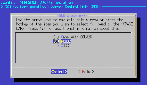
2.3.3.1. HPADC (High Performance ADC)
HPADC is an ADC capable of high-speed sampling.
The clock system diagram of HPADC is shown below.
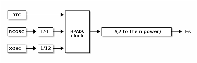
The HPADC clock is determined by fixedly dividing the clock source. The sampling frequency is determined by dividing the ADC clock by a power of two.
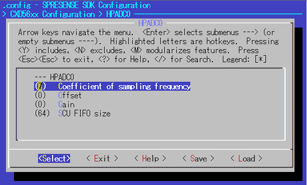
The n value can be changed by the following SDK configuration.
CXD56xx Configuration -> HPADC0 -> Coefficient of sampling frequency (CONFIG_CXD56_HPADC0_FREQ)
CXD56xx Configuration -> HPADC1 -> Coefficient of sampling frequency (CONFIG_CXD56_HPADC1_FREQ)
The possible range of n value depends on the SCU clock mode.
-
In case of SCU clock mode = RTC
n 9 10 11 Fs(Hz)
64
32
16
Available
〇
〇
〇
-
In case of SCU clock mode = RCOSC/XOSC
n 0 1 2 3 4 5 6 7 Fs(Hz)
2M
1M
512K
256K
128K
64K
32K
16K
Available
×
×
×
×
×
〇
〇
〇
2.3.3.2. LPADC (Low Power ADC)
LPADC is an ADC that operates at a lower sampling rate but lower power consumption than HPADC. The clock system diagram of LPADC is shown below.
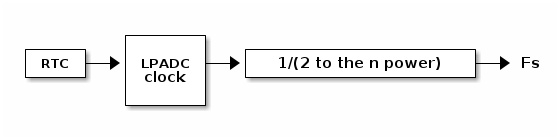
LPADC operates based on RTC clock. The sampling frequency is determined by dividing the clock by a power of two.
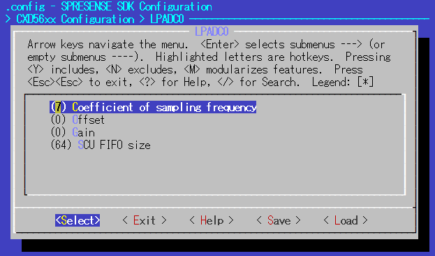
The n value can be changed by the following SDK configuration.
CXD56xx Configuration -> LPADC0 -> Coefficient of sampling frequency (CONFIG_CXD56_LPADC0_FREQ)
CXD56xx Configuration -> LPADC1 -> Coefficient of sampling frequency (CONFIG_CXD56_LPADC1_FREQ)
CXD56xx Configuration -> LPADC2 -> Coefficient of sampling frequency (CONFIG_CXD56_LPADC2_FREQ)
CXD56xx Configuration -> LPADC3 -> Coefficient of sampling frequency (CONFIG_CXD56_LPADC3_FREQ)
The possible range of n value depends on the SCU clock mode.
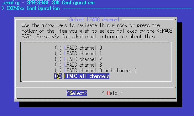
LPADC has 4 channels in total. Depending on whether LPADC is used only 1 channel, 2 channels or 4 channels,
the upper limit of sampling frequency is changed. The possible values of n in each case are shown below.
-
In case of SCU clock mode = RTC
-
When any one of LPADC channels 0 to 3 is selected
n 11 12 13 14 15 Fs(Hz)
16
8
4
2
1
Available
〇
〇
〇
〇
〇
-
When two channels of LPADC channel 0 and 1 are selected
n 12 13 14 15 Fs(Hz)
4
2
1
0.5
Available
〇
〇
〇
〇
-
When four channels of LPADC channel 0,1,2 and 3 are selected
n 11 12 13 14 15 Fs(Hz)
4
2
1
0.5
0.25
Available
〇
〇
〇
〇
〇
-
-
In case of SCU clock mode = RCOSC
-
When any one of LPADC channels 0 to 3 is selected
n 3 4 5 6 7 8 9 10 11 12 13 14 15 Fs(Hz)
4K
2K
1K
512
256
128
64
32
16
8
4
2
1
Available
〇
〇
〇
〇
〇
〇
〇
〇
〇
〇
〇
〇
〇
-
When two channels of LPADC channel 0 and 1 are selected
n 6 7 8 9 10 11 12 13 14 15 Fs(Hz)
256
128
64
32
16
8
4
2
1
0.5
Available
〇
〇
〇
〇
〇
〇
〇
〇
〇
〇
-
When four channels of LPADC channel 0,1,2 and 3 are selected
n 7 8 9 10 11 12 13 14 15 Fs(Hz)
64
32
16
8
4
2
1
0.5
0.25
Available
〇
〇
〇
〇
〇
〇
〇
〇
〇
-
-
In case of SCU clock mode = XOSC
-
When any one of LPADC channels 0 to 3 is selected
n 2 3 4 5 6 7 8 9 10 11 12 13 14 15 Fs(Hz)
8K
4K
2K
1K
512
256
128
64
32
16
8
4
2
1
Available
〇
〇
〇
〇
〇
〇
〇
〇
〇
〇
〇
〇
〇
〇
-
When two channels of LPADC channel 0 and 1 are selected
n 6 7 8 9 10 11 12 13 14 15 Fs(Hz)
256
128
64
32
16
8
4
2
1
0.5
Available
〇
〇
〇
〇
〇
〇
〇
〇
〇
〇
-
When four channels of LPADC channel 0,1,2 and 3 are selected
n 7 8 9 10 11 12 13 14 15 Fs(Hz)
64
32
16
8
4
2
1
0.5
0.25
Available
〇
〇
〇
〇
〇
〇
〇
〇
〇
-
2.4. PWM example application
This section describes the usage of PWM example application.
2.4.1. How to build
This is the build procedure via the command line.
When you use IDE, refer to the explanation of the following configuration.
-
Change directory to
sdkIf you do source
build-env.shscript, you can use the tab completion of theconfig.pytool.cd spresense/sdk source tools/build-env.sh
-
Kernel configuration and building
In this case, kernel configuration uses release-defconfig.
If you have already built the kernel, you can skip this step.tools/config.py --kernel release make buildkernel
-
SDK configuration and building
Execute the configuration by specifying
examples/pwmas an argument ofconfig.py.
If the build is successful, anuttx.spkfile will be created under thesdkdirectory.tools/config.py examples/pwm make
-
Flashing
nuttx.spkinto Spresense boardIn this case, the serial port is
/dev/ttyUSB0, and the baudrate of the uploading speed is500000bps. Please change according to your environment.tools/flash.sh -c /dev/ttyUSB0 -b 500000 nuttx.spk
2.4.2. Operation check
Open the serial terminal, and run pwm command.
-
Open the serial terminal
This is an example of using a minicom terminal with
/dev/ttyUSB0as the serial port and115200as the baudrate.minicom -D /dev/ttyUSB0 -b 115200 -
Type
pwmcommand on NuttShell promptThe usage of
pwmcommand is shown below.nsh> pwm -h Usage: pwm [OPTIONS] Arguments are "sticky". For example, once the PWM frequency is specified, that frequency will be re-used until it is changed. "sticky" OPTIONS include: [-p devpath] selects the PWM device. Default: /dev/pwm0 Current: /dev/pwm0 [-f frequency] selects the pulse frequency. Default: 1000 Hz Current: 1000 Hz [-d duty] selects the pulse duty as a percentage. Default: 50 % Current: 50 % [-t duration] is the duration of the pulse train in seconds. Default: 5 Current: 5 [-h] shows this message and exits
e.g) Outputs PWM signal with a frequency of 2000 Hz and a duty ratio of 30% to PWM1 during 10 seconds.
nsh> pwm -p /dev/pwm1 -f 2000 -d 30 -t 10
- -p
-
There are a total of 4 PWM pins. Specify -p /dev/pwm[0-3] with the -p option.
- -f
-
Set the PWM <frequency> [Hz].
- -d
-
Set the <duty> ratio (the fraction of the high period of the period) [%] from 1 to 99.
- -t
-
Output the PWM signal for the specified <duration> time [s].
2.4.3. PWM frequency and duty ratio
PWM frequency depends on the clock selected by SCU clock mode.
The SCU clock is shown below.
-
Same with SCU32K → RTC 32.768kHz
-
RCOSC → approximately 8.2MHz
-
XOSC → 13MHz obtained by dividing TCXO 26MHz by CONFIG_CXD56_SCU_XOSC_DIV(=2)
The period of the PWM signal waveform is determined by the PWM_CYCLE count of the SCU clock as shown in the figure below. The Low output period is determined by the PWM_THRESH count. The upper limit of the count is 0xffff.
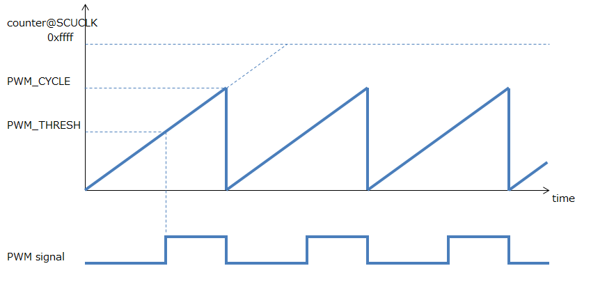
The PWM frequency range is:
1 <= PWM frequency <= SCU clock / 2
For example, if RCOSC is selected for the SCU clock, the frequency will be from 1 Hz to approximately 4 MHz.
Regarding the duty ratio, the low and high periods are calculated from the approximate value with the specified -d option.
Therefore the output waveform does not have an accurate duty ratio and may include rounding errors.
3. GPS Tutorials
3.1. Sample Application of GPS(GNSS)
This chapter shows the operation procedure of GPS(GNSS) sample application.
3.1.1. Build & Flash
-
Move to the folder where you cloned the Spresense SDK, and enter the
sdkfolder name:cd spresense/sdk -
Set up the NuttX kernel configuration
tools/config.py --kernel release -
Set up the SDK configuration To enable the
gnssexample application, selectexamples/gnss.tools/config.py examples/gnssPlease refer to How to configure for details on the configuration. -
Build the example image:
make buildkernel
make
Please refer to How to build for details on the build. A
nuttx.spkfile will be created in thesdkfolder aftermakehas successfully finished. -
Just the same as Hello World example, flash the
nuttx.spkto Spresense withtools/flash.sh.tools/flash.sh -c /dev/ttyUSB0 nuttx.spk -
When flashing the board is completed the board is restarted automatically.
3.1.2. GPS operation confirmation
Loading nuttx.spk to Spresense, you can run the GNSS program.
Open the serial terminal.
minicom -D /dev/ttyUSB0 -b 115200 -s
Execute gnss command, the gnss is a built-in application. The following text will be displayed:
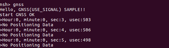
If positioning is not available, you see this message:
No Positioning Data
And the time is displayed that is from 0 o’clock count up when GNSS start.
If the Spresense can receive GPS signals from the satellites (clear view to the sky etc), the time in UTC will be displayed in approximately 1 minute, and the GPS position in approximately 3 minutes.
Hour:9, minute:13, sec:20, usec:559
LAT 35.25.6303
LNG 139.22.1986
Similar text as shown above is displayed, and latitude and longitude can be read.
4. Audio Tutorials
4.1. Sample Application of Audio Player
This chapter shows the operation procedure of the sample application of Audio Player.
4.1.1. Build & Flash
Here shows the build process by using command line.
-
Move to the
sdkdirectory:Run
build-env.shscript provides tab keyword complementation ofconfig.pytool.cd spresense/sdk source tools/build-env.sh
-
Configure and build the kernel.
In this case, release-defconfig is selected for kernel configuration.
If you already built the kernel, you can skip this process.tools/config.py --kernel release make buildkernel
-
Configure and build SDK.
Set
examples/audio_playeras argument ofconfig.pyand execute configuration. When build succeeded,nuttx.spkbinary file will be generated undersdkdirectory.tools/config.py examples/audio_player make
-
Load
nuttx.spkto Spresense board.In this case, serial port is
/dev/ttyUSB0and baudrate is500000bps, both are set.
This parameter should be set to fit to your environment.tools/flash.sh -c /dev/ttyUSB0 -b 500000 nuttx.spk -
For Audio Player, it is necessary to load the DSP binary for decode. You can choose to place the DSP binary on either a SD card or SPI-Flash. Here is how to load from the SD card.
Specify the path of DSP binary in the application code (
audio_player_main.cxx). Inaudio_player_main.cxx, it is specified byDSPBIN_FILE_PATH.#define DSPBIN_FILE_PATH "/mnt/sd0/BIN"This code shows that the SD card is selected.
If you would like to use SPI-flash, please specify /mnt/spif/BIN.When you read SD card on PC,
/mnt/sd0/BINwill appear asBIN/under the root directory.
Create this directory and place the DSP for the required codec here.When you want to decode MP3 files,
selectMP3DECunderspresense/sdk/modules/audio/dsp/ -
Write the music file which you would like to play to the SD card.
audio_player_main.cxxis specified inPLAYBACK_FILE_PATH.#define PLAYBACK_FILE_PATH "/mnt/sd0/AUDIO"Therefore, please insert SD card to PC and create
AUDIOdirectory under the root of SD card. Next, put the audio files inAUDIOdirectory. It can also be placed in subdirectories. -
The current Audio Player sample is playing a simple PlayList. So, specify the location and file name of the playlist file and play music files. In
audio_player_main.cxx, specify the path withPLAYLIST_FILE_PATHand the file name is specified inPLAYLIST_FILE_NAME.#define PLAYLIST_FILE_PATH "/mnt/sd0/PLAYLIST" #define PLAYLIST_FILE_NAME "TRACK_DB.CSV"Please create
PLAYLIST/under root directory of SD card, and putTRACK_DB.CSVinto there.For the contents of
TRACK_DB.CSV, seeREADME.txtunderspresense/sdk/modules/audio/playlist/.
Then you can play your playlist.
4.1.2. Operation check of Audio Player
When this nuttx.spk is loaded to the Spresense board, the Audio Player program can be executed.
Open the serial terminal as you did in the Hello sample.
minicom -D /dev/ttyUSB0 -b 115200 -s
When you run the audio_player app that was builtin,
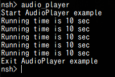
The log is displayed and the audio is played back.
If an error occurs, refer to Error Information of Audio SubSystem.
4.1.3. Appendix : Customize audio signal process
|
So far, you could run the audio_player application with this tutorial. From here on, it explains about optional function which add custom signal process. |
In AudioPlayer sample, you can perform your own signal processing on the playing audio.
If you would like to do this, you need to enable [Use postprocess] in the config menu.
-
Enable Postprocess.
Open the config menu.
tools/cofig.py -mCheck
[Use Postprocess].[Examples] [Audio player example] [Use Postprocess] <= YFor more information on Postprocess, please refer to SDK Developer Guide Set preprocess. -
Do builds
makeWhen build completed successfully,
POSTPROCbinary file will be generated underspresense/examples/audio_player/worker/.
Please put this file on/mnt/sd0/BIN(If you read SD card on PC, it’sBIN/).In this sample application, POSTPROCincludes a simple RCfilter by default.
If you want to customize your own signal processing etc, please refer to here.Please playback audio files with Postprocess Enable/Disable, and check difference. Refer How to playback.
== About customizing DSP binary (POSTPROC)
This chapter shows how to customize the DSP binary (POSTPROC).
4.1.3.1. Step 1. Edit the code of POSTPROC
Describes the code structure of POSTPROC and the editing location.
The code is divided into two parts: the part to edit the user and the part provided as a framework.
user-edited code
It is a code that users should edit mainly.
It can make unique signal processing by editing these codes.
The DSP code is in the worker directory, which has the userproc directory.
The user writes signal processing only in the userproc directory, and other things basically do not need to be changed.
Since main.cpp provides startup processing and data communication control with Main CPU, do not change it.

Startup processing and DSP communication processing are written. There is no need to edit.
It is a header file that defines the communication command with DSP.
Describe your necessary parameters in this file.
The header file of user code.
The source file of user code.
Write or call signal processing to this file.
APIs are provided for user code
userproc.cpp provides a framework for Init , Exec , Flush , Set commands.
The user code can support the processing in DSP by writing the unique contents.
Describes the process that the user should write.
(* By default, an RC filter is included as a sample.)
This framework assumed that the state transition inside DSP like in the figure below.
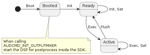
Program the process by each command as following flow.
-
DSP starts when AUDCMD_INIT_OUTPUTMIXER is called.
-
Set necessary parameters (number of channels, bit length, etc.) with the
Initcommand. -
When recording starts, the captured audio data is periodically sent to the DSP with the
Execcommand, so it can do a unique filter processing. -
If you want to change DSP internal parameters at any time, you can use
Setcommand .The execution timing of this command is in the order of command reception includingExec. -
When recording stop, the
Flushcommand is sent after the last audio data onExec, so if termination processing is necessary, the processing is performed here.
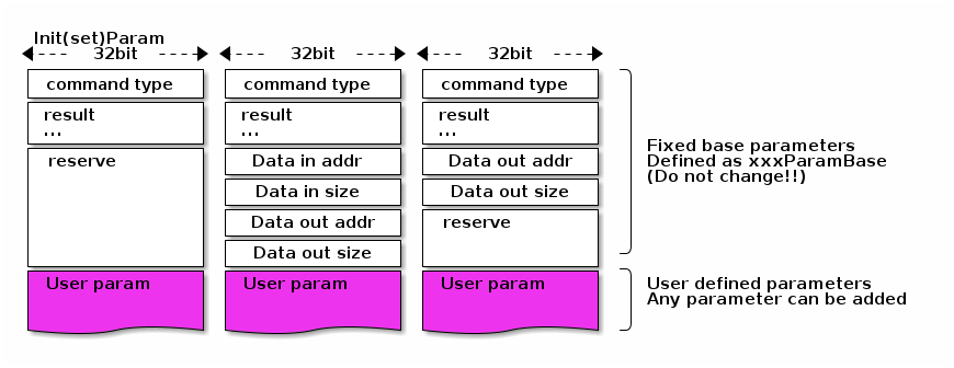
The data types used by each function are described in userproc_command.h , and the contents can be freely written.
The format of each command is as shown below.
The minimum required parameters are placed in the top white area. Please do not change these.
The part of User param (purple part)in the figure below in userproc_command.h , you should define your parameters.
Each command is discribed in the following.
struct InitParam : public CustomprocCommand::CmdBase-
Parameter for
Initprocessing.
All parameter defined byreserved, so you will change them to necessary parameters such as the number of channels and bit length.
struct ExecParam : public CustomprocCommand::CmdBase-
Parameter for
Execprocessing.
The address and size of audio data is defined inCustomprocCommand::ExecParamBasefrom which it is inherited as inExecParamin the figure above.
For details, seesdk/modules/include/audio/dsp_framework/customproc_command_base.h.
struct FlushParam : public CustomprocCommand::CmdBase-
Parameter for
Flushprocessing.
The address and size of audio data is defined inCustomprocCommand::FlushParamBasefrom which it is inherited as inExecParamin the figure above.
For details, seesdk/modules/include/audio/dsp_framework/customproc_command_base.h.
struct SetParam : public CustomprocCommand::CmdBase-
Parameter for
Setprocessing.
Define various dynamically changed parameters. By default, RC filter On/Off and coefficients are defined as sample.
The following functions are written in userproc.cpp . The contents can be written freely.
Processing is performed according to each command definition.
void UserProc::init(InitParam *)-
Write your initialize processing according to InitParam.
It is executed by AUDCMD_INITMPP command from application code.
(Nothing is done by default)
void UserProc::exec(ExecParam *)-
Write your signal processing according to ExecParam. When you start recording, it will be called periodically from the SDK.
1 frame is 640 samples when recording setup is LPCM, 1152 for MP3 (but 1728 at 16 kHz) samples.
Get data from the input data address, do your signal processing, and write to the output data address. (RC filtering is written by default)
void UserProc::flush(FlushParam *)-
Write the flush (termination) process according to FlushParam.
when recording stops, it will be called only once from the SDK.
For example, If it is delay filter like IIR or FIR filter,flushmay be needed as filer clear.
If there is data to be output, write to the output data address.
(Nothing is done by default)
void UserProc::set(SetParam *)-
Write the set (change parameter) process according to SetParam.
It is executed by AUDCMD_SETMPPPARAM command from application code.
(By default, the RC filter coefficient is set.)
4.1.3.2. Step 2. Build POSTPROC binary
If you enable Postprocess in configuration, POSTPROC binary will be created automatically when this application is built.
The path created is POSTPROC under spresense/examples/audio_player/worker .
Put this in the /mnt/sd0/BIN ( \BIN viewed from the PC) folder on the SD card.
4.2. Sample application of Audio Recorder
This chapter shows the operation procedure of the sample application of Audio Recorder.
4.2.1. Build & Flash
Here shows the build process by using command line.
-
Move to the
sdkdirectory:Run
build-env.shscript provides tab keyword complementation ofconfig.pytool.cd spresense/sdk source tools/build-env.sh
-
Configure and build the kernel.
In this case, release-defconfig is selected for kernel configuration.
If you already built the kernel, you can skip this process.tools/config.py --kernel release make buildkernel
-
Configure and build SDK.
Set
examples/audio_recorderas argument ofconfig.pyand execute configuration. When build succeeded,nuttx.spkbinary file will be generated undersdkdirectory.tools/config.py examples/audio_recorder make
-
Load
nuttx.spkto Spresense board.In this case, serial port is
/dev/ttyUSB0and baudrate is500000bps, both are set.
This parameter should be set to fit to your environment.tools/flash.sh -c /dev/ttyUSB0 -b 500000 nuttx.spk -
For Audio Recorder, it is necessary to load the DSP binary for encoding. You can choose to place the DSP binary on either an SD card or SPI-Flash. Here is how to load from the SD card.
Specify the path of DSP binary in the application code. In
audio_recorder_main.cxx, it is specified byDSPBIN_PATH.#define DSPBIN_PATH "/mnt/sd0/BIN"This code shows that the SD card is selected.
If you would like to use SPI-flash, please specify /mnt/spif/BIN.When you read SD card on PC,
/mnt/sd0/BINwill appear asBIN/under the root directory.
Create this directory and place the DSP for the required codec here.When you would like to encode MP3 files,
selectMP3ENCfile which is placed underspresense/sdk/modules/audio/dsp/The combinations of Codec type and DSP binary for other encoding are shown in the table below.
Codec DSP Binary MP3
MP3ENC
LPCM
SRC
4.2.2. Operation check of Audio Recorder
When this nuttx.spk is loaded to the Spresense board, the Audio recorder program can be executable.
Open the serial terminal as you did in the Hello sample.
minicom -D /dev/ttyUSB0 -b 115200 -s
When you run the audio_recorder app that was builtin,
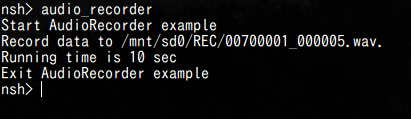
The log is displayed and the audio is recording.
The recorded audio can be played back on a PC. At that time, there is an audio file in REC/ under the SD card root directory.
In audio_recorder_main.cxx, the record file path is RECFILE_ROOTPATH , please change the application code as needed.
#define RECFILE_ROOTPATH "/mnt/sd0/REC"+
This code shows that the audio data will be recorded in REC/ directory on the SD card.
+
If an error occurs, refer to Error Information of Audio SubSystem.
4.2.3. Appendix : Customize audio signal process
|
So far, you could run the audio_recorder application with this tutorial. From here on, it explains about optional function which add custom signal process. |
In AudioRecorder sample, you can perform your own signal processing on the recorded audio.
If you would like to do this, you need to enable [Use preprocess] in the config menu.
-
Enable Preprocess.
Open the config menu.
tools/cofig.py -mCheck
[Use preprocess].[Examples] [Audio recorder example] [Use preprocess] <= YFor more information on Preprocess, please refer to SDK Developer Guide Set preprocess. -
Do builds
makeWhen build completed successfully,
PREPROCbinary file will be generated underspresense/examples/audio_recorder/worker/src.
Please put this file on/mnt/sd0/BIN(If you read SD card on PC, it’sBIN/).In this sample application, PREPROCincludes a simple RCfilter by default.
If you want to customize your own signal processing etc, please refer to here.Please playback audio files which are recorded by Preprocess Enable/Disable, and check difference. Refer How to record and playback.
== About customizing DSP binary (PREPROC)
this chapter shows how to customize the DSP binary (PREPROC).
4.2.3.1. Step 1. Edit the code of PREPROC
Describes the code structure of PREPROC and the editing location.
The code is divided into two parts: the part to edit the user and the part provided as a framework.
user-edited code
It is a code that users should edit mainly.
It can make unique signal processing by editing these codes.+
The DSP code is in the worker directory, which has the userproc directory.
The user writes signal processing only in the userproc directory, and other things basically do not need to be changed.
Since main.cpp provides startup processing and data communication control with Main CPU, do not change it.
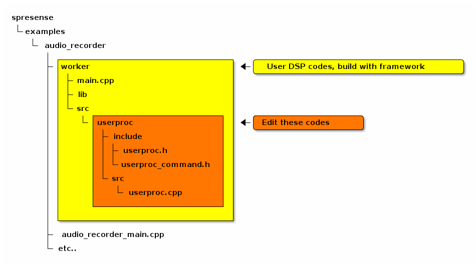
Startup processing and DSP communication processing are written. There is no need to edit.
It is a header file that defines the communication command with DSP.
Describe your necessary parameters in this file.
The header file of user code.
The source file of user code.
Write or call signal processing to this file.
APIs are provided for user code
userproc.cpp provides a framework for Init , Exec , Flush , Set commands.
The user code can support the processing in DSP by writing the unique contents.
Describes the process that the user should write.
(* By default, an RC filter is included as a sample.)
This framework assumed that the state transition inside DSP like in the figure below.
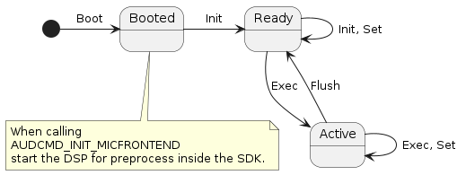
Program the process by each command as following flow.
-
DSP starts when AUDCMD_INIT_MICFRONTEND is called.
-
Set necessary parameters (number of channels, bit length, etc.) with the
Initcommand. -
When recording starts, the captured audio data is periodically sent to the DSP with the
Execcommand, so it can do a unique filter processing. -
If you want to change DSP internal parameters at any time, you can use
Setcommand .The execution timing of this command is in the order of command reception includingExec. -
When recording stop, the
Flushcommand is sent after the last audio data onExec, so if termination processing is necessary, the processing is performed here.
The data types used by each function are described in userproc_command.h , and the contents can be freely written.
The format of each command is as shown below.
The minimum required parameters are placed in the top white area. Please do not change these.
The part of User param (purple part)in the figure below in userproc_command.h , you should define your parameters.
Each command is discribed in the following.
struct InitParam : public CustomprocCommand::CmdBase-
Parameter for
Initprocessing.
All parameter defined byreserved, so you will change them to necessary parameters such as the number of channels and bit length.
struct ExecParam : public CustomprocCommand::CmdBase-
Parameter for
Execprocessing.
The address and size of audio data is defined inCustomprocCommand::ExecParamBasefrom which it is inherited as inExecParamin the figure above.
For details, seesdk/modules/include/audio/dsp_framework/customproc_command_base.h.
struct FlushParam : public CustomprocCommand::CmdBase-
Parameter for
Flushprocessing.
The address and size of audio data is defined inCustomprocCommand::FlushParamBasefrom which it is inherited as inExecParamin the figure above.
For details, seesdk/modules/include/audio/dsp_framework/customproc_command_base.h.
struct SetParam : public CustomprocCommand::CmdBase-
Parameter for
Setprocessing.
Define various dynamically changed parameters. By default, RC filter On/Off and coefficients are defined as sample.
The following functions are written in userproc.cpp . The contents can be written freely.
Processing is performed according to each command definition.
void UserProc::init(InitParam *)-
Write your initialize processing according to InitParam.
It is executed by AUDCMD_INIT_PREPROCESS_DSP command from application code.
(Nothing is done by default)
void UserProc::exec(ExecParam *)-
Write your signal processing according to ExecParam. When you start recording, it will be called periodically from the SDK.
1 frame is 768 samples when recording setup is LPCM, 1152 for MP3 (but 1728 at 16 kHz) samples.
Get data from the input data address, do your signal processing, and write to the output data address. (RC filtering is written by default)
void UserProc::flush(FlushParam *)-
Write the flush (termination) process according to FlushParam.
when recording stops, it will be called only once from the SDK.
For example, If it is delay filter like IIR or FIR filter,flushmay be needed as filer clear.
If there is data to be output, write to the output data address.
(Nothing is done by default)
void UserProc::set(SetParam *)-
Write the set (change parameter) process according to SetParam.
It is executed by AUDCMD_SET_PREPROCESS_DSP command from application code.
(By default, the RC filter coefficient is set.)
4.2.3.2. Step 2. Build PREPROC binary
If you enable Preprocess in configuration, PREPROC binary will be created automatically when this application is built.
The path created is PREPROC under spresense/examples/audio_recorder/worker/src .
Put this in the /mnt/sd0/BIN ( \BIN viewed from the PC) folder on the SD card.
5. System tools
Spresense SDK provides the system tools on NuttShell.
| Category | System tool | Description |
|---|---|---|
LOG |
A utility tool to change the log level dynamically |
|
A utility tool to dump the logging information on Backup SRAM |
||
A utility tool to save the logging information on Backup SRAM into SPI-Flash |
||
GPIO |
A utility tool to get/set GPIO/pin settings |
|
A utility tool for GPIO interrupt |
||
I2C |
A utility tool to communicate with I2C device |
|
PMIC |
A utility tool to control PMIC(PowerManagement IC) |
|
USB |
||
Zmodem |
||
Stack |
A utility tool to monitor stack usages of all tasks and threads |
6. USB MSC system tool
This section describes the utility tool to use USB MSC (Mass Storage Class) feature.
When the USB MSC function is enabled, the Host PC can directly access the SD card on the Spresense board.
6.1. How to build
This is the build procedure via the command line.
When you use IDE, refer to the explanation of the following configuration.
-
Change directory to
sdkIf you do source
build-env.shscript, you can use the tab completion of theconfig.pytool.cd spresense/sdk source tools/build-env.sh
-
Kernel configuration and building
In this case, kernel configuration uses release-defconfig.
If you have already built the kernel, you can skip this step.tools/config.py --kernel release make buildkernel
-
SDK configuration and building
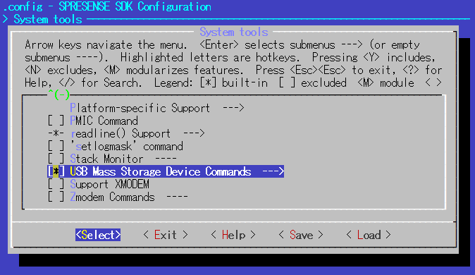
Since the SD card is mounted as a USB MSC, open the menuconfig with the SD card function enabled.
./tools/config.py device/sdcard -mEnable System tools > USB Mass Storage Device Commands, and save and finish configuration.

makeIf the build is successful, a
nuttx.spkfile will be created under thesdkdirectory. -
Flashing
nuttx.spkinto Spresense boardIn this case, the serial port is
/dev/ttyUSB0, and the baudrate of the uploading speed is500000bps. Please change according to your environment.tools/flash.sh -c /dev/ttyUSB0 -b 500000 nuttx.spk
6.2. Operation check
With the SD card inserted in the extension board, connect the USB connector of the extension board to the Host PC with a USB cable.
-
Open the serial terminal
This is an example of using a minicom terminal with
/dev/ttyUSB0as the serial port and115200as the baudrate.minicom -D /dev/ttyUSB0 -b 115200 -
Type
msconncommand on NuttShell promptnsh> msconn mcsonn_main: Creating block drivers mcsonn_main: Configuring with NLUNS=1 mcsonn_main: handle=d038d50 mcsonn_main: Bind LUN=0 to /dev/mmcsd0 mcsonn_main: Connected
The new removable disk is recognized by the Host PC, and the contents of the SD card on the extension board can be accessed from the Host PC.
-
To terminate the USB MSC function, type
msdiscommand on NuttShell prompt.nsh> msdis msdis: Disconnected
7. USB CDC/ACM system tool
This section describes the utility tool to use USB CDC/ACM feature.
When the USB CDC/ACM function is enabled, the USB of the extension board can be used as a serial port.
7.1. How to build
This is the build procedure via the command line.
When you use IDE, refer to the explanation of the following configuration.
-
Change directory to
sdkIf you do source
build-env.shscript, you can use the tab completion of theconfig.pytool.cd spresense/sdk source tools/build-env.sh
-
Kernel configuration and building
In this case, kernel configuration uses release-defconfig.
If you have already built the kernel, you can skip this step.tools/config.py --kernel release make buildkernel
-
SDK configuration and building
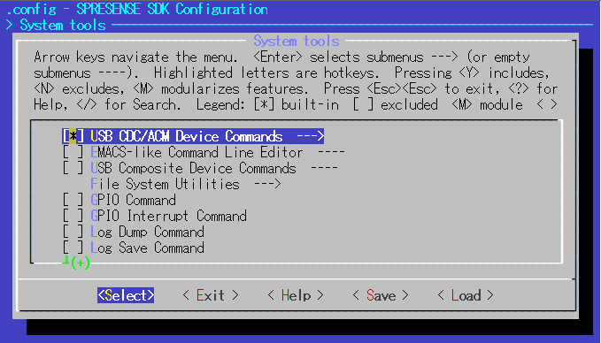
Open the menuconfig.
./tools/config.py -mEnable System tools > USB CDC/ACM Device Commands, and save and finish configuration.

makeIf the build is successful, a
nuttx.spkfile will be created under thesdkdirectory. -
Flashing
nuttx.spkinto Spresense boardIn this case, the serial port is
/dev/ttyUSB0, and the baudrate of the uploading speed is500000bps. Please change according to your environment.tools/flash.sh -c /dev/ttyUSB0 -b 500000 nuttx.spk
7.2. Operation check
Connect the USB connector of the extension board to the Host PC with a USB cable.
-
Open the serial terminal
This is an example of using a minicom terminal with
/dev/ttyUSB0as the serial port and115200as the baudrate.minicom -D /dev/ttyUSB0 -b 115200 -
Type
serconcommand on NuttShell promptnsh> sercon sercon: Registering CDC/ACM serial driver sercon: Successfully registered the CDC/ACM serial driver
The new device file
/dev/ttyACM0is generated on the Spresense board, and a new COM port can be found on the Host PC. You can use this port for serial communication via USB. -
To terminate the USB CDC/ACM function, type
serdiscommand on NuttShell prompt.nsh> serdis serdis: Disconnected
8. Zmodem file transfer
This section describes how to send and receive files between Host PC and Spresense board using Zmodem transfer.
8.1. How to build
This is the build procedure via the command line.
When you use IDE, refer to the explanation of the following configuration.
-
Change directory to
sdkIf you do source
build-env.shscript, you can use the tab completion of theconfig.pytool.cd spresense/sdk source tools/build-env.sh
-
Kernel configuration and building
In this case, kernel configuration uses release-defconfig.
If you have already built the kernel, you can skip this step.tools/config.py --kernel release make buildkernel
-
SDK configuration and building
Execute the configuration by specifying
feature/zmodemas an argument ofconfig.py.
If the build is successful, anuttx.spkfile will be created under thesdkdirectory.tools/config.py feature/zmodem make
-
Flashing
nuttx.spkinto Spresense boardIn this case, the serial port is
/dev/ttyUSB0, and the baudrate of the uploading speed is500000bps. Please change according to your environment.tools/flash.sh -c /dev/ttyUSB0 -b 500000 nuttx.spk
8.2. Operation check
Use a serial terminal that supports the Zmodem transfer.
This is using minicom terminal for a example.
If minicom and lrzsz are not installed, install them in advance.
sudo apt install minicom lrzsz
Open a minicom terminal with /dev/ttyUSB0 as the serial port and 115200 as the baudrate.
minicom -D /dev/ttyUSB0 -b 115200
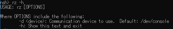
You can use Zmodem’s rz (receive) and sz (send) commands on NuttShell prompt.
- The usage of rz command
-

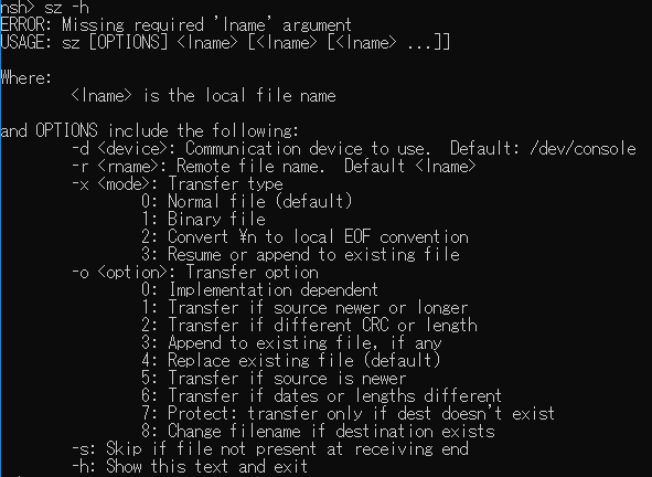
- The usage of sz command
-

8.2.1. File transfer from Host PC to Spresense board
How to transfer files from the HostPC to the Spresense board is shown below.
-
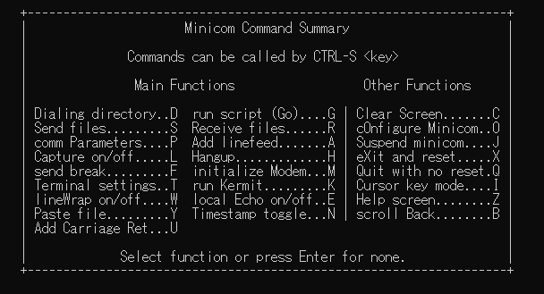
On minicom terminal, type
CTRL-aandzkey, and open the menu (This shortcut key assignment can be changed by the user. See the minicom manual for details.)
Then press theskey and select Send files.
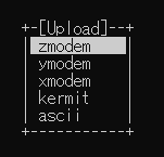
-
Select zmodem with cursor key and execute with
Enterkey.
-
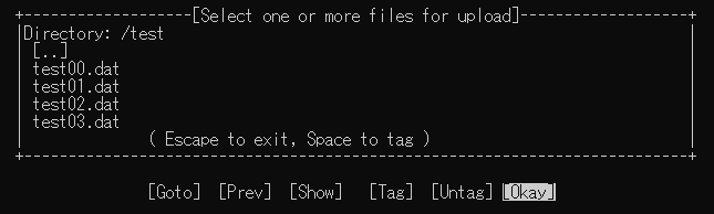
Move the folder with the cursor key and the space key, and select the file you want to transfer.
Select a folder with the cursor keys and press the space key twice to move to the folder.
Select the file with the cursor keys and the space key, and press theEnterkey to start the transfer.
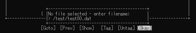
Alternatively, you can press the
Enterkey and input the file name to execute the transfer.
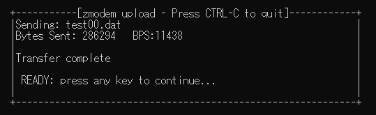
-
The file transfer starts and the transfer is completed when "Transfer complete" is displayed.

-
The transfer destination of the file on the Spresense board can be changed with CONFIG_SYSTEM_ZMODEM_MOUNTPOINT.
In the default configuration, files are transferred to Flash of/mnt/spif.
If you use TeraTerm terminal, you can send the selected file from File→ Transfer→ ZMODEM→ Send from TeraTerm menu.
|
8.2.2. File transfer from Spresense board to Host PC
How to transfer files from the Spresense board to the HostPC is shown below.
-
On NuttShell prompt, specify the file you want to transfer to the argument of the
szcommand.
Enter the full path name starting with/.
The following example uses the-x 1binary transfer option.nsh> sz -x 1 /mnt/spif/test00.dat
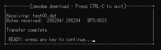
-
The file transfer starts and the transfer is completed when "Transfer complete" is displayed.

-
The file is transferred into the folder where minicom was executed on the Host PC.
If you use TeraTerm terminal, you can receive the file from File→ Transfer→ ZMODEM→ Receive of TeraTerm menu.
|
9. How to start applications automatically
This section describes how to start the user application automatically instead of the NuttShell prompt.
9.1. Start-up script
By using a start-up script, the system can run according to the script
and the application program can be automatically executed when the power is turned on.
The startup script can support NuttShell commands with the user application, and the control syntax such as if-then-else-fi or while-do-done.
See NuttShell (NSH) documentation for details.
9.1.1. Usage of start-up script
This is an example to start the examples/hello application automatically.
(The explanation about the configuration and build of NuttX Kernel is omitted.)
-
Open the menuconfig with the hello application enabled.
./tools/config.py -m examples/hello -
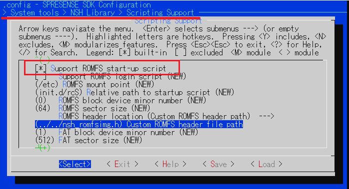
Enable
Support ROMFS start-up scriptSystem tools --> NSH Library ---> Scripting Support
-
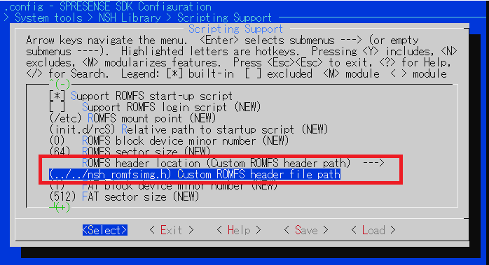
Select
Custom ROMFS header pathinROMFS header locationand
input../../nsh_romfsimg.hinCustom ROMFS header file pathand save the configuration.Specify the location of nsh_romfsimg.hwith a relative path from the sdk/system/nshlib directory.
-
Next, create a startup script named
rcS.templateunder thesdkdirectory,
and describeechocommand andhellocommand as below.cat spresense/sdk/rcS.template echo Start-up hello application hello -
By using a
mkromfsimg.shtool, generatensh_romfsimg.hfromrcS.template.cd spresense/sdk ./tools/mkromfsimg.sh . ls nsh_romfsimg.h nsh_romfsimg.h
-
Build and flash the program as usual.
make
tools/flash.sh -c /dev/ttyUSB0 nuttx.spk
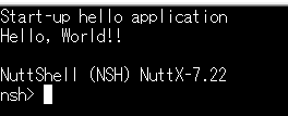
-
When you turn on the power of the board, you can confirm that the hello application described in the script has been started before NuttShell prompt is displayed.

9.1.2. Change script location
-
Refer to the following procedure if you’d like to change the location of
rcS.template.cat spresense/examples/hello/rcS.template echo Start-up hello application hello -
Change the directory where
rcS.templateis located and generatensh_romfsimg.hby using mkromfsimg.sh tool.cd spresense/examples/hello ../../sdk/tools/mkromfsimg.sh ../../sdk ls nsh_romfsimg.h nsh_romfsimg.h
-
Open configuration menu, and input
../../../examples/hello/nsh_romfsimg.hintoCustom ROMFS header file path.Specify the location of nsh_romfsimg.hwith a relative path from the sdk/system/nshlib directory. -
The rest of the build procedure is the same as before.
9.2. SDK Entrypoint
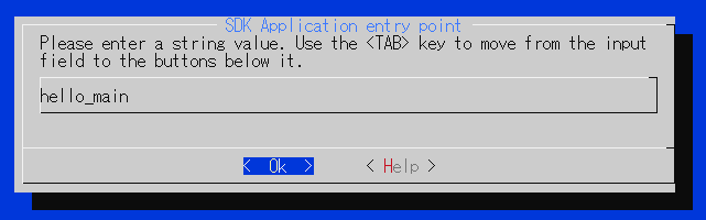
There is another way that uses CONFIG_SDK_USER_ENTRYPOINT than the startup script.
The default configuration of CONFIG_SDK_USER_ENTRYPOINT is nsh_main, but
if you change it to hello_main, then the hello application would be launched on startup.
| The application needs to be initialized at startup. Add #include <sys/boardctl.h> and boardctl(BOARDIOC_INIT, 0) into the user entrypoint function. |
#include <sys/boardctl.h>

#ifdef CONFIG_BUILD_KERNEL
int main(int argc, FAR char *argv[])
#else
int hello_main(int argc, char *argv[])
#endif
{
  /* Initialize apllication */
  boardctl(BOARDIOC_INIT, 0);

  printf("Hello, World!!\n");
  return 0;
}