
1. Examples
The examples in the Spresense SDK are installed as a built-in command in the NuttShell environment. Refer to the README.txt file in the directory of each example for additional details about the required SDK configuration etc.
In SDK v2.0 or later, the original NuttX applications have also been added to Examples list.
(See here for tutorials in SDK old version 1.x.)
|
If you are building for the first time, please refer to the getting started guide. There are detailed instructions about how to configure and run the built program. |
1.1. SDK examples
1.2. NuttX examples
2. Peripheral Driver Tutorials
2.1. RTC alarm example application
This section describes the usage of RTC alarm example application.
2.1.1. How to build
This is the build procedure via the command line.
When you use IDE, refer to the explanation of the following configuration.
-
Change directory to
sdkIf you do source
build-env.shscript, you can use the tab completion of theconfig.pytool.cd spresense/sdk source tools/build-env.sh
-
SDK configuration and building
Execute the configuration by specifying
examples/alarmas an argument ofconfig.py.
If the build is successful, anuttx.spkfile will be created under thesdkdirectory.tools/config.py examples/alarm make
-
Flashing
nuttx.spkinto Spresense boardIn this case, the serial port is
/dev/ttyUSB0, and the baudrate of the uploading speed is500000bps. Please change according to your environment.tools/flash.sh -c /dev/ttyUSB0 -b 500000 nuttx.spk
2.1.2. Operation check
Open the serial terminal, and run alarm command.
-
Open the serial terminal
This is an example of using a minicom terminal with
/dev/ttyUSB0as the serial port and115200as the baudrate.minicom -D /dev/ttyUSB0 -b 115200 -
Type
alarmcommand on NuttShell promptThe usage of
alarmcommand is shown below.nsh> alarm ERROR: Invalid number of arguments: 0 USAGE: alarm <seconds> Where: <seconds> The number of seconds until the alarm expires.<seconds> means the relative time (seconds). For example,
alarm 5will trigger the RTC alarm after 5 seconds.nsh> alarm 5 alarm_daemon started alarm_daemon: Running Opening /dev/rtc0 Alarm 0 set in 5 seconds nsh> alarm_demon: alarm 0 received
2.1.3. RTC alarm with power saving features
Here is an example of using the alarm command in combination with the power saving features.
Spresense provides power saving features such as Deep Sleep and Cold Sleep modes.
It can enter these sleep states using the poweroff command.
And, by the RTC alarm function, it can wake up from these sleep states.
For more information about Deep Sleep and Cold Sleep, refer to Sleep Mode.
2.1.3.1. Wake up from Deep Sleep mode
In the following example, an alarm is set after 10 seconds,
and the system enters Deep Sleep mode by shutdown command.
After 10 seconds, the alarm is expires and the system wakes up from the Deep Sleep state.
nsh> alarm 10
alarm_daemon started
alarm_daemon: Running
Opening /dev/rtc0
Alarm 0 set in 10 seconds
nsh> poweroff

NuttShell (NSH) NuttX-8.2
nsh>
2.1.3.2. Wake up from Cold Sleep mode
In the following example, an alarm is set after 10 seconds,
and the system enters Cold Sleep mode by poweroff 1 command.
After 10 seconds, the alarm is expires and the system wakes up from the Cold Sleep state.
nsh> alarm 10
alarm_daemon started
alarm_daemon: Running
Opening /dev/rtc0
Alarm 0 set in 10 seconds
nsh> poweroff 1

NuttShell (NSH) NuttX-8.2
nsh>
2.1.4. Other RTC commands
The date command allows you to set the RTC time and display the current RTC time.
nsh> help date
date usage:  date [-s "MMM DD HH:MM:SS YYYY"]
e.g) set 2019/12/1 23:34:56 to RTC
nsh> date -s "Dec 1 23:34:56 2019"
The current time is displayed by the date command.
nsh> date
Dec 01 23:35:14 2019
The RTC time is kept during sleep modes such as Deep/Cold Sleep and rebooting by the reboot command.
However, if the power supply is turned off or the reset button is pressed, the RTC time will be clear.
The following example shows that the RTC time is retained even after the system reboot with the reboot command.
nsh> date
Dec 01 23:41:08 2019
nsh> reboot

NuttShell (NSH) NuttX-8.2
nsh> date
Dec 01 23:41:12 2019
nsh>
2.2. Watchdog example application
This section describes the usage of Watchdog example application.
2.2.1. How to build
This is the build procedure via the command line.
When you use IDE, refer to the explanation of the following configuration.
-
Change directory to
sdkIf you do source
build-env.shscript, you can use the tab completion of theconfig.pytool.cd spresense/sdk source tools/build-env.sh
-
SDK configuration and building
Execute the configuration by specifying
examples/watchdogas an argument ofconfig.py.
If the build is successful, anuttx.spkfile will be created under thesdkdirectory.tools/config.py examples/watchdog make
-
Flashing
nuttx.spkinto Spresense boardIn this case, the serial port is
/dev/ttyUSB0, and the baudrate of the uploading speed is500000bps. Please change according to your environment.tools/flash.sh -c /dev/ttyUSB0 -b 500000 nuttx.spk
2.2.2. Operation check
Open the serial terminal, and run wdog command.
-
Open the serial terminal
This is an example of using a minicom terminal with
/dev/ttyUSB0as the serial port and115200as the baudrate.minicom -D /dev/ttyUSB0 -b 115200 -
Type
wdogcommand on NuttShell promptThe usage of
wdogcommand is shown below.nsh> wdog -h Usage: wdog [-h] [-d <pingdelay>] [-p <pingtime>] [-t <timeout>] Initialize the watchdog to the <timeout>. Start the watchdog timer. Ping for the watchdog for <pingtime> seconds, then let it expire. Options include: [-d <pingdelay>] = Time delay between pings in milliseconds. Default: 500 [-p <pingtime>] = Selects the <pingtime> time in milliseconds. Default: 5000 [-t timeout] = Time in milliseconds that the example will ping the watchdog before letting the watchdog expire. Default: 2000 [-h] = Shows this message and exits- -d
-
Clear the watchdog timer by calling ioctl(fd, WDIOC_KEEPALIVE, 0) with the specified <pingdelay> period [msec].
- -p
-
Keeps the watchdog clear during the specified <pingtime> period [msec].
- -t
-
Set the period of watchdog timer by calling ioctl(fd, WDIOC_SETTIMEOUT, (unsigned long)wdog.timeout) with the specified <timeout> [msec].
This example application can confirm that the system reboots when the watchdog timer is expired.
The following is an example of running the wdog command.
If you type wdog command without argument, the period of watchdog timer is set to the default 2 seconds.
During 5 seconds, the watchdog timer continues to be cleared at a cycle of 500 msec.
After that, the watchdog timer will be expired and the system will reboot without clearing the watchdog timer.
nsh> wdog
  ping elapsed=0
  ping elapsed=500
  ping elapsed=1000
  ping elapsed=1500
  ping elapsed=2000
  ping elapsed=2500
  ping elapsed=3000
  ping elapsed=3500
  ping elapsed=4000
  ping elapsed=4500
  NO ping elapsed=5000
  NO ping elapsed=5500
  NO ping elapsed=6000
up_assert: Assertion failed at file:irq/irq_unexpectedisr.c line: 65 task: Idle Task
up_dumpstate: sp:     0d0279d4
up_dumpstate: IRQ stack:
up_dumpstate:   base: 0d027a00
up_dumpstate:   size: 00000800
up_dumpstate:   used: 00000120
up_stackdump: 0d0279c0: 00000000 0d003e3d 0d0291a8 0d02975c 00000000 00000002 466cc9d4 0d002f69
up_stackdump: 0d0279e0: 0d002f55 0d00703d 00000000 0d02975c 0d028a20 00000003 00000000 0d006fd5
up_dumpstate: sp:     0d029830
up_dumpstate: User stack:
up_dumpstate:   base: 0d029840
up_dumpstate:   size: 00000400
up_dumpstate:   used: 00000000
up_stackdump: 0d029820: 9b7feebc 1f86add5 00000000 0d002e75 0d029844 001567bc 2df7cabf 00000000
up_registerdump: R0: 00000000 0d026bcc 0d02df68 00000014 0d026b54 0d028a20 00000003 00000000
up_registerdump: R8: 0d026ca0 f0bbaf7f dc9161d8 466cc9d4 00000003 0d029830 0d002e79 0d008792
up_registerdump: xPSR: 21000000 BASEPRI: 00000000 CONTROL: 00000000
up_registerdump: EXC_RETURN: ffffffe9
up_taskdump: Idle Task: PID=0 Stack Used=0 of 0
up_taskdump: hpwork: PID=1 Stack Used=344 of 2028
up_taskdump: lpwork: PID=2 Stack Used=352 of 2028
up_taskdump: lpwork: PID=3 Stack Used=352 of 2028
up_taskdump: lpwork: PID=4 Stack Used=352 of 2028
up_taskdump: init: PID=5 Stack Used=1032 of 8172
up_taskdump: cxd56_pm_task: PID=6 Stack Used=320 of 996
up_taskdump: wdog: PID=8 Stack Used=528 of 2028

NuttShell (NSH) NuttX-8.2
nsh>
2.3. ADC example application
This section describes the usage of ADC example application.
2.3.1. How to build
This is the build procedure via the command line.
When you use IDE, refer to the explanation of the following configuration.
-
Change directory to
sdkIf you do source
build-env.shscript, you can use the tab completion of theconfig.pytool.cd spresense/sdk source tools/build-env.sh
-
SDK configuration and building
Execute the configuration by specifying
examples/adc_monitoras an argument ofconfig.py.
If the build is successful, anuttx.spkfile will be created under thesdkdirectory.tools/config.py examples/adc_monitor make
-
Flashing
nuttx.spkinto Spresense boardIn this case, the serial port is
/dev/ttyUSB0, and the baudrate of the uploading speed is500000bps. Please change according to your environment.tools/flash.sh -c /dev/ttyUSB0 -b 500000 nuttx.spk
2.3.2. Operation check
Open the serial terminal, and run adc_monitor command.
-
Open the serial terminal
This is an example of using a minicom terminal with
/dev/ttyUSB0as the serial port and115200as the baudrate.minicom -D /dev/ttyUSB0 -b 115200 -
Type
adc_monitorcommand on NuttShell promptThe usage of
adc_monitorcommand is shown below.nsh> adc_monitor -h Usage: adc_monitor [OPTIONS] Arguments are "sticky". For example, once the ADC device is specified, that device will be re-used until it is changed. "sticky" OPTIONS include: [-p devpath] selects the ADC device. /dev/lpadc0, 1, 2, 3, /dev/hpadc0, 1 Current: /dev/lpadc0 [-n count] set the number of reads. Current: 10 [-h] shows this message and exits
- -p
-
There are a total of 6 ADC dedicated pins. Specify -p /dev/lpadc[0-3] or /dev/hpadc[0-1] with the -p option. The relationship between pin numbers and device files on the Spresense board is shown below.
Pin number
A0
A1
A2
A3
A4
A5
/dev file
/dev/lpadc0
/dev/lpadc1
/dev/lpadc2
/dev/lpadc3
/dev/hpadc0
/dev/hpadc1
- -n
-
Specify the number of measurements.
For example, you can read AD converted data from HPADC0(A4) 10 times. The data from HPADC0 is stored to the buffer and displays the average, minimum, and maximum values. ADC data is 16-bit signed data and the range is -32767 to 32767.
nsh> adc -p /dev/hpadc0 -n 10
ADC example - Name:/dev/hpadc0 bufsize:16
Ave:-32767 Min:-32767 Max:-32767 Cnt:8
Ave:-32767 Min:-32767 Max:-32767 Cnt:8
Ave:-32767 Min:-32767 Max:-32767 Cnt:8
Ave:14673 Min:14668 Max:14676 Cnt:8
Ave:14681 Min:14677 Max:14684 Cnt:8
Ave:14690 Min:14687 Max:14694 Cnt:8
Ave:14684 Min:14680 Max:14690 Cnt:8
Ave:14677 Min:14672 Max:14682 Cnt:8
Ave:14677 Min:14675 Max:14682 Cnt:8
Ave:14672 Min:14667 Max:14677 Cnt:8
ADC example end
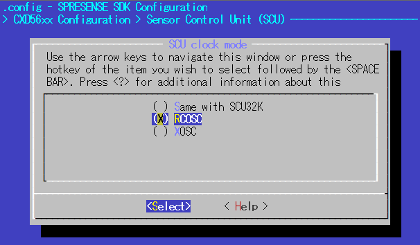
2.3.3. ADC sampling frequency
ADC sampling frequency depends on the clock selected by SCU clock mode.
2.3.3.1. HPADC (High Performance ADC)
HPADC is an ADC capable of high-speed sampling.
The clock system diagram of HPADC is shown below.
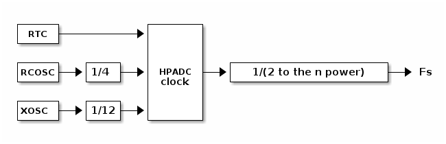
The HPADC clock is determined by fixedly dividing the clock source. The sampling frequency is determined by dividing the ADC clock by a power of two.
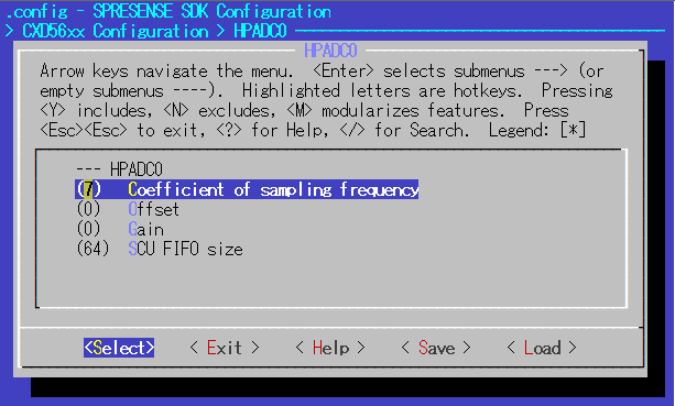
The n value can be changed by the following SDK configuration.
System Type -> CXD56xx Package Configuration -> Peripheral Support ->
  ADC -> HPADC0 -> Coefficient of sampling frequency (CONFIG_CXD56_HPADC0_FREQ)
  ADC -> HPADC1 -> Coefficient of sampling frequency (CONFIG_CXD56_HPADC1_FREQ)
The possible range of n value depends on the SCU clock mode.
-
In case of SCU clock mode = RTC
n 9 10 11 Fs(Hz)
64
32
16
Available
〇
〇
〇
-
In case of SCU clock mode = RCOSC/XOSC
n 0 2 3 4 5 6 7(*1) Fs(Hz)
540-550K(*3)
512K
256K
128K
64K
32K
16K
Available
△(*4)
△(*2)
△(*2)
△(*2)
〇
〇
〇
(*1): SCU clock mode = RCOSC,
n= 7 by default configuration, thenFsis 16KHz.
(*2): If CONFIG_CXD56_HPADC0_HIGHSPEED=y, it supportsFsup to 512KHz.
(*3): If CONFIG_CXD56_HPADC0_HIGHSPEED=y,Fsdepends on the performance of the SCU sequencer, and is about 540-550KHz.
(*4): Ifnis 0, the smoothing CIC filter is disabled and ADC outputs the raw value with 10bit resolution.If CONFIG_CXD56_HPADC0_HIGHSPEED is enabled,
HPADC1, LPADC, and I2C/SPI SCU sequencers will not be available.The recommended configuration at the high-speed sampling rate (512KHz) is shown as below.
Configuration Value Description CONFIG_CXD56_ADC
y
Enable ADC.
CONFIG_CXD56_HPADC0
y
Enable HPADC0.
CONFIG_CXD56_HPADC1
n
Disable HPADC1.
CONFIG_CXD56_LPADC
n
Disable LPADC.
CONFIG_CXD56_HPADC0_FREQ
2
Set the Fs to 512KHz.
CONFIG_CXD56_HPADC0_HIGHSPEED
y
Enable the high-speed option.
CONFIG_CXD56_HPADC0_INPUT_GAIN_M6DB
y
Set the input gain to -6dB.
CONFIG_CXD56_I2C0_SCUSEQ
n
Disable I2C0 SCU sequencer.
CONFIG_CXD56_I2C1_SCUSEQ
n
Disable I2C1 SCU sequencer.
CONFIG_CXD56_SPI3_SCUSEQ
n
Disable SPI3 SCU sequencer.
CONFIG_CXD56_SCU_XOSC
y
Set the SCU clock source to XOSC.
2.3.3.2. LPADC (Low Power ADC)
LPADC is an ADC that operates at a lower sampling rate but lower power consumption than HPADC. The clock system diagram of LPADC is shown below.
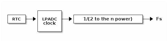
LPADC operates based on RTC clock. The sampling frequency is determined by dividing the clock by a power of two.
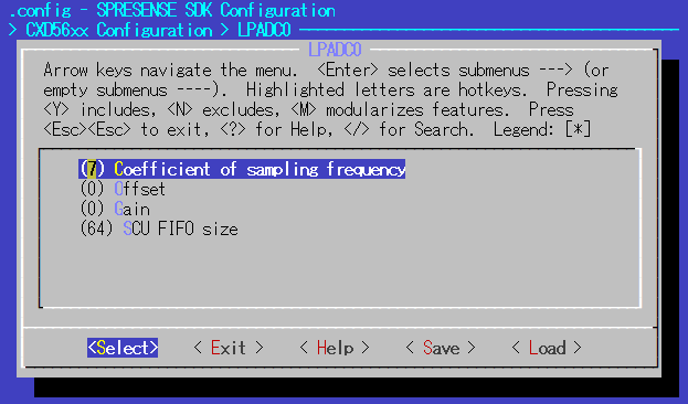
The n value can be changed by the following SDK configuration.
System Type -> CXD56xx Package Configuration -> Peripheral Support ->
  ADC -> LPADC0 -> Coefficient of sampling frequency (CONFIG_CXD56_LPADC0_FREQ)
  ADC -> LPADC1 -> Coefficient of sampling frequency (CONFIG_CXD56_LPADC1_FREQ)
  ADC -> LPADC2 -> Coefficient of sampling frequency (CONFIG_CXD56_LPADC2_FREQ)
  ADC -> LPADC3 -> Coefficient of sampling frequency (CONFIG_CXD56_LPADC3_FREQ)
The possible range of n value depends on the SCU clock mode.
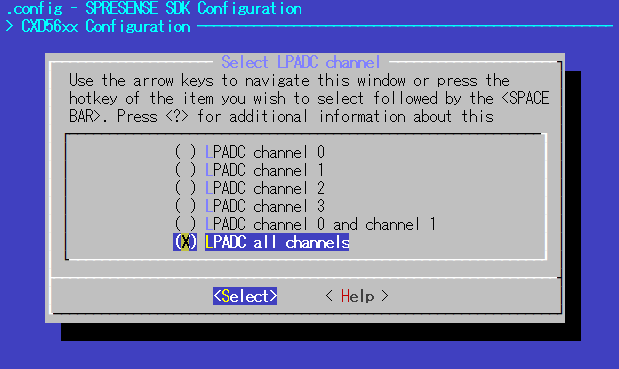
LPADC has 4 channels in total. Depending on whether LPADC is used only 1 channel, 2 channels or 4 channels,
the upper limit of sampling frequency is changed. The possible values of n in each case are shown below.
-
In case of SCU clock mode = RTC
-
When any one of LPADC channels 0 to 3 is selected
n 11 12 13 14 15 Fs(Hz)
16
8
4
2
1
Available
〇
〇
〇
〇
〇
-
When two channels of LPADC channel 0 and 1 are selected
n 12 13 14 15 Fs(Hz)
4
2
1
0.5
Available
〇
〇
〇
〇
-
When four channels of LPADC channel 0,1,2 and 3 are selected
n 11 12 13 14 15 Fs(Hz)
4
2
1
0.5
0.25
Available
〇
〇
〇
〇
〇
-
-
In case of SCU clock mode = RCOSC
-
When any one of LPADC channels 0 to 3 is selected
n 3 4 5 6 7 8 9 10 11 12 13 14 15 Fs(Hz)
4K
2K
1K
512
256
128
64
32
16
8
4
2
1
Available
〇
〇
〇
〇
〇
〇
〇
〇
〇
〇
〇
〇
〇
-
When two channels of LPADC channel 0 and 1 are selected
n 6 7 8 9 10 11 12 13 14 15 Fs(Hz)
256
128
64
32
16
8
4
2
1
0.5
Available
〇
〇
〇
〇
〇
〇
〇
〇
〇
〇
-
When four channels of LPADC channel 0,1,2 and 3 are selected
n 7(*) 8 9 10 11 12 13 14 15 Fs(Hz)
64
32
16
8
4
2
1
0.5
0.25
Available
〇
〇
〇
〇
〇
〇
〇
〇
〇
(*): LPADC all channels, SCU clock mode = RCOSC,
n= 7 by default configuration
-
-
In case of SCU clock mode = XOSC
-
When any one of LPADC channels 0 to 3 is selected
n 2 3 4 5 6 7 8 9 10 11 12 13 14 15 Fs(Hz)
8K
4K
2K
1K
512
256
128
64
32
16
8
4
2
1
Available
〇
〇
〇
〇
〇
〇
〇
〇
〇
〇
〇
〇
〇
〇
-
When two channels of LPADC channel 0 and 1 are selected
n 6 7 8 9 10 11 12 13 14 15 Fs(Hz)
256
128
64
32
16
8
4
2
1
0.5
Available
〇
〇
〇
〇
〇
〇
〇
〇
〇
〇
-
When four channels of LPADC channel 0,1,2 and 3 are selected
n 7 8 9 10 11 12 13 14 15 Fs(Hz)
64
32
16
8
4
2
1
0.5
0.25
Available
〇
〇
〇
〇
〇
〇
〇
〇
〇
-
2.4. PWM example application
This section describes the usage of PWM example application.
2.4.1. How to build
This is the build procedure via the command line.
When you use IDE, refer to the explanation of the following configuration.
-
Change directory to
sdkIf you do source
build-env.shscript, you can use the tab completion of theconfig.pytool.cd spresense/sdk source tools/build-env.sh
-
SDK configuration and building
Execute the configuration by specifying
examples/pwmas an argument ofconfig.py.
If the build is successful, anuttx.spkfile will be created under thesdkdirectory.tools/config.py examples/pwm make
-
Flashing
nuttx.spkinto Spresense boardIn this case, the serial port is
/dev/ttyUSB0, and the baudrate of the uploading speed is500000bps. Please change according to your environment.tools/flash.sh -c /dev/ttyUSB0 -b 500000 nuttx.spk
2.4.2. Operation check
Open the serial terminal, and run pwm command.
-
Open the serial terminal
This is an example of using a minicom terminal with
/dev/ttyUSB0as the serial port and115200as the baudrate.minicom -D /dev/ttyUSB0 -b 115200 -
Type
pwmcommand on NuttShell promptThe usage of
pwmcommand is shown below.nsh> pwm -h Usage: pwm [OPTIONS] Arguments are "sticky". For example, once the PWM frequency is specified, that frequency will be re-used until it is changed. "sticky" OPTIONS include: [-p devpath] selects the PWM device. Default: /dev/pwm0 Current: /dev/pwm0 [-f frequency] selects the pulse frequency. Default: 1000 Hz Current: 1000 Hz [-d duty] selects the pulse duty as a percentage. Default: 50 % Current: 50 % [-t duration] is the duration of the pulse train in seconds. Default: 5 Current: 5 [-h] shows this message and exits
e.g) Outputs PWM signal with a frequency of 2000 Hz and a duty ratio of 30% to PWM1 during 10 seconds.
nsh> pwm -p /dev/pwm1 -f 2000 -d 30 -t 10
- -p
-
There are a total of 4 PWM pins. Specify -p /dev/pwm[0-3] with the -p option.
- -f
-
Set the PWM <frequency> [Hz].
- -d
-
Set the <duty> ratio (the fraction of the high period of the period) [%] from 1 to 99.
- -t
-
Output the PWM signal for the specified <duration> time [s].
2.4.3. PWM frequency and duty ratio
PWM frequency depends on the clock selected by SCU clock mode.
The SCU clock is shown below.
-
Same with SCU32K → RTC 32.768kHz
-
RCOSC → approximately 8.2MHz
-
XOSC → 13MHz obtained by dividing TCXO 26MHz by CONFIG_CXD56_SCU_XOSC_DIV(=2)
The period of the PWM signal waveform is determined by the PWM_CYCLE count of the SCU clock as shown in the figure below. The Low output period is determined by the PWM_THRESH count. The upper limit of the count is 0xffff.
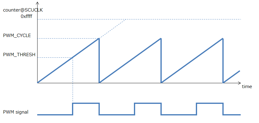
The PWM frequency range is:
1 <= PWM frequency <= SCU clock / 2
For example, if RCOSC is selected for the SCU clock, the frequency will be from 1 Hz to approximately 4 MHz.
Regarding the duty ratio, the low and high periods are calculated from the approximate value with the specified -d option.
Therefore the output waveform does not have an accurate duty ratio and may include rounding errors.
3. GPS Tutorials
3.1. Sample Application of GPS(GNSS)
This chapter shows the operation procedure of GPS(GNSS) sample application.
3.1.1. Build & Flash
-
Move to the folder where you cloned the Spresense SDK, and enter the
sdkfolder name:cd spresense/sdk -
Set up the SDK configuration To enable the
gnssexample application, selectexamples/gnss.tools/config.py examples/gnss -
Build the example image:
make
A nuttx.spk file will be created in the sdk folder after make has successfully finished.
-
Just the same as Hello World example, flash the
nuttx.spkto Spresense withtools/flash.sh.tools/flash.sh -c /dev/ttyUSB0 nuttx.spk -
When flashing the board is completed the board is restarted automatically.
3.1.2. GPS operation confirmation
Loading nuttx.spk to Spresense, you can run the GNSS program.
Open the serial terminal.
minicom -D /dev/ttyUSB0 -b 115200 -s
Execute gnss command, the gnss is a built-in application. The following text will be displayed:
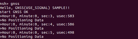
If positioning is not available, you see this message:
No Positioning Data
And the time is displayed that is from 0 o’clock count up when GNSS start.
If the Spresense can receive GPS signals from the satellites (clear view to the sky etc), the time in UTC will be displayed in approximately 1 minute, and the GPS position in approximately 3 minutes.
Hour:9, minute:13, sec:20, usec:559
LAT 35.25.6303
LNG 139.22.1986
Similar text as shown above is displayed, and latitude and longitude can be read.
3.2. Sample Application of GNSS Add-on
This chapter describes the operation of the GNSS Add-on example application.
In addition to the basic usage of acquiring the positioning information using the GNSS Add-on board, this application implements several optional features that can be used as a GPS data logger. Please use it as a reference when creating your own original application.
-
NMEA output support
-
Positioning cycle setting support
-
Time setting using 1PPS signal
-
File logging function
-
Periodic positioning for power saving
-
Automatic application execution
-
Michibiki disaster and crisis management report
3.2.1. How to build
This is the build procedure via the command line.
When you use IDE, refer to the explanation of the following configuration.
-
Change directory to
sdkIf you do source
build-env.shscript, you can use the tab completion of theconfig.pytool.cd spresense/sdk source tools/build-env.sh
-
SDK configuration and building
Execute the configuration by specifying
examples/gnss_addonas an argument ofconfig.py.
If the build is successful, anuttx.spkfile will be created under thesdkdirectory.tools/config.py examples/gnss_addon make
-
Flashing
nuttx.spkinto Spresense boardIn this case, the serial port is
/dev/ttyUSB0, and the baudrate of the uploading speed is500000bps. Please change according to your environment.tools/flash.sh -c /dev/ttyUSB0 -b 500000 nuttx.spk
3.2.2. Operation check
Open a serial terminal and run the command gnss_addon.
-
Open the serial terminal.
This is an example of using a minicom terminal with
/dev/ttyUSB0as the serial port and115200as the baudrate.minicom -D /dev/ttyUSB0 -b 115200 -
Type
gnss_addoncommand on NuttShell promptThe
gnss_addoncommand with an argument of-hwill displayUsage.nsh> gnss_addon -h Usage: gnss_addon [-n] [-q] [-p] [-c <cycle>] [-f <fixcnt>] [-s <sleep>] [-o <filepath>] Options: -n: Enable NMEA output -q: Enable NMEA DC Report output with "-n" option -p: Enable 1PPS signal -c <cycle>: Positioning cycle (100, 125, 200, 250, 500 or 1000 x N) [msec] (default:1000) -f <fixcnt>: Positioning fix count (default:300) -s <sleep>: Sleeping time [sec] (default:0) -o <filepath>: Full path to a log fileThe
gnss_addoncommand first displays the firmware version and starts positioning according to the specified argument. After the position is fixed and the position information is obtained, if the number of consecutive successful positioning attempts specified by-fis reached, the positioning operation is stopped and the system goes into sleep mode for the number of seconds specified by-s. By using the automatic execution of the application, you can repeat the periodic operation of starting positioning again after waking up from the sleep state. -
Set up automatic application execution
Set up this application to run automatically upon power-up using the method described in How to start applications automatically.
For example, to perform 100 positioning and 60 seconds of sleep periodically, create the following
init.rcscript.nsh> echo "gnss_addon -f 100 -s 60" > /mnt/spif/init.rc
When you reboot with the
rebootcommand or by pressing the reset button, it will start automatic execution according to the script.nsh> reboot Run /mnt/spif/init.rc. sh [13:100] NuttShell (NSH) NuttX-12.3.0 nsh> GNSS Add-on example application: NMEA: Disable (DC Report: Disable), 1PPS: Disable After positioning fix 100 times, sleep 60 sec. FW version: v00.144 2000/01/02 00:00:03.000 0.000000 0.000000 0.000 [N]
You can enter NuttShell commands while positioning is running. If you want to stop the automatic startup, remove the
init.rcscript and restart it.nsh> rm /mnt/spif/init.rc nsh> reboot
3.2.3. Program Description
-
Basic positioning sequence
This section describes the basic procedure for acquiring position information using the GNSS Add-on board. As the interface is compatible with the built-in GNSS, the basic usage is the same as in Sample Application of GPS(GNSS).
The device file name of the built-in GNSS is
/dev/gpsand that of the GNSS Add-on driver is/dev/gps2.GNSS device file Built-in GNSS
/dev/gps
GNSS Add-on
/dev/gps2
First,
open()the device file/dev/gps2.fd = open("/dev/gps2", O_RDONLY);Start positioning by
CXD56_GNSS_IOCTL_STARTcommand ofioctl()for the opened driver.ret = ioctl(fd, CXD56_GNSS_IOCTL_START, CXD56_GNSS_STMOD_HOT); if (ret < 0) { printf("ERROR: start ret=%d, errno=%d\n", ret, errno); goto errout; }The following is a method for reading periodic positioning data.
It repeatedly waits for the notification of positioning information by
poll()and then reads the positioning data by usingread(). The interval of this notification depends on the setting of the positioning cycle described below. By default, it is notified once per second. In addition,LED3(GPIO_LED4)on the main board is blinking bytoggle_led()function so that it can be monitored externally that positioning operation is in progress./* Wait for positioning data to be notified. */ ret = poll(fds, 1, -1); if (ret < 0) { printf("ERROR: poll ret=%d, errno=%d\n", ret, errno); break; } /* Read the positioning data. */ ret = read(fd, &posdat, sizeof(posdat)); if (ret != sizeof(posdat)) { printf("ERROR: read ret=%d, errno=%d\n", ret, errno); break; } toggle_led();The code to print acquired positioning data to a serial terminal is shown below.
  /* Print the positioning data. */

  if (args.nmea)
    {
      print_nmea(&posdat);
    }
  else
    {
      print_posdat(&posdat, fp);
    }
How to output in NMEA format is described below. By default, UTC time, latitude [degree], longitude [degree], altitude [m], and positioning status information are displayed. The meaning of the positioning status is as below table.
positioning status state [N]
Non-fixed state
[A]
Fixed state
[D]
Fixed state and DGPS is effective
After the specified number of positioning completes, stop positioning (
CXD56_GNSS_IOCTL_STOP) usingioctl(). After saving the backup data (CXD56_GNSS_IOCTL_SAVE_BACKUP_DATA) for the next startup, put the device on the GNSS Add-on board into deep sleep mode (CXD56_GNSS_IOCTL_SLEEP). The deep sleep state will consume less power than the idle state after power-on./* Stop GNSS, save the backup data and put it deep sleep mode * for power saving. */ ret = ioctl(fd, CXD56_GNSS_IOCTL_STOP, 0); if (ret < 0) { printf("ERROR: stop ret=%d, errno=%d\n", ret, errno); } ret = ioctl(fd, CXD56_GNSS_IOCTL_SAVE_BACKUP_DATA, 0); if (ret < 0) { printf("ERROR: save ret=%d, errno=%d\n", ret, errno); } ret = ioctl(fd, CXD56_GNSS_IOCTL_SLEEP, CXD56_GNSS_DEEPSLEEP); if (ret < 0) { printf("ERROR: sleep ret=%d, errno=%d\n", ret, errno); }If you want to wake up the device from deep sleep mode, call the
CXD56_GNSS_IOCTL_WAKEUPcommand ofioctl(). In this example application, the wake-up command is called immediately afteropen()in order to wake up a device in deep sleep mode when thegnss_addoncommand is repeatedly executed. There is no problem if this command is called when the device is in the wake-up state./* Wakeup as GNSS may be in sleep mode. */ ret = ioctl(fd, CXD56_GNSS_IOCTL_WAKEUP, 0); if (ret < 0) { printf("ERROR: wakeup ret=%d, errno=%d\n", ret, errno); }Finally,
close()the device./* Close a GNSS Add-on device driver. */ ret = close(fd); if (ret < 0) { printf("ERROR: close ret=%d, errno=%d\n", ret, errno); }These are the basic sequence for positioning. In the following sections, other optional functions will be explained.
-
NMEA output
To output in NMEA format, add
-nto the argument of thegnss_addoncommand. It can be used in combination with other arguments.nsh> gnss_addon -n [other options]
The code to output NMEA is implemented in
gnss_addon_nmea.c. If you want to limit the NMEA sentences to be output, remove unnecessary ones from the following code./* Select NMEA sentence */ NMEA_SetMask2(NMEA_GGA_ON | NMEA_GLL_ON | NMEA_GSA_ON | NMEA_GSV_ON | NMEA_GNS_ON | NMEA_RMC_ON | NMEA_VTG_ON | NMEA_QZQSM_ON | NMEA_ZDA_ON); -
Michibiki disaster and crisis management report (DCR)
To output the Michibiki DCR, add
-nand-qto the argument of thegnss_addoncommand. It can be used in combination with other arguments.nsh> gnss_addon -n -q [other options]
When the DCR is received, the
$QZQSMsentence is displayed in the NMEA format.Please update the firmware on the GNSS Add-on board to v00.144 or later in order to receive the DCR.
-
1PPS signal output
To output a 1PPS signal, specify
-pas an argument to thegnss_addoncommand. It can be used in combination with other arguments.nsh> gnss_addon -p [other options]
To enable the 1PPS signal output, call the
CXD56_GNSS_IOCTL_SET_1PPS_OUTPUTcommand ofioctl().The 1PPS signal is a pulse signal at 1 second intervals synchronized to UTC time. This signal is output from the
CL2land on the GNSS Add-on board. It is also output from thePIN_I2S0_DATA_OUTpin on the GNSS Add-on board by shorting the no-mount resistorR16. See the GNSS Add-on board schematic in hardware design document for details.ret = ioctl(fd, CXD56_GNSS_IOCTL_SET_1PPS_OUTPUT, 1); if (ret < 0) { printf("ERROR: 1pps ret=%d, errno=%d\n", ret, errno); }A time synchronization method using the 1PPS signal is also implemented in this example. As this example code receives the 1PPS signal as a GPIO interrupt, it is necessary to connect the 1PPS signal to the
PIN_I2S0_DATA_OUTpin in order to use it as is. Connect theCL2land and thePIN_I2S0_DATA_OUTpin externally, or shortR16resistor.The time information contained in the positioning data is delayed by several hundred milliseconds from actual time due to the discrepancy between when the device get time and when Spresense receives and reads the notification. If a more accurate time is desired, a 1PPS signal can be used. The next 1PPS signal is sent at exactly the time when the time information in the positioning data is rounded down to the nearest second +1 second. For example, if the time in the positioning data is 12:34:56, this is later than the actual time, but the next time when the PPS signal is interrupted is exactly at 12:34:57, the actual time.
The
gnss_addon_pps.cexample code remembers the time +1 second from the positioning data and sets the time in the RTC when the 1PPS signal is received as an interrupt. The RTC can be set to a more accurate real time than the time in the positioning data, although there is a certain amount of error due to the dispatch time from the interrupt handler to the thread, the write time to the RTC, and the time accuracy of the RTC being 32 kHz. Also, for debugging purposes,LED2(GPIO_LED3)on the main board blinks when the 1PPS signal is received as an interrupt, allowing you to check whether the 1PPS signal is correctly received as an interrupt. -
Positioning cycle
You can change the positioning cycle by specifying
-c <cycle msec>as an argument to thegnss_addoncommand. If nothing is specified, the default cycle is 1000 msec (=1 Hz). Supported cycles are 100, 125, 200, 250, 500, or N times 1000 (N≠0). If an unsupported cycle is set, it will beInvalid Parametererror and command execution will be terminated.For example, to set 500 msec (=2 Hz), execute as below.
nsh> gnss_addon -c 500 [other options]
The
CXD56_GNSS_IOCTL_SET_OPE_MODEcommand ofioctl()is used to set the positioning cycle.struct cxd56_gnss_ope_mode_param_s opemode; opemode.mode = 1; opemode.cycle = args.cycle; ret = ioctl(fd, CXD56_GNSS_IOCTL_SET_OPE_MODE, (uint32_t)&opemode); if (ret < 0) { printf("ERROR: cycle ret=%d, errno=%d\n", ret, errno); goto errout; } -
File logging function
Specify
-o <file name>as an argument to thegnss_addoncommand to save the positioning results to a file instead of serial output. To insert an SD card into the extension board and record a log file tonmea.logon the SD card, execute as below.nsh> gnss_addon -n -s 60 -o /mnt/sd0/nmea.log [other options]
Saving files to the SD card is done at the timing of
fclose()before going to sleep. Therefore, you can safely retrieve the saved file by setting the sleep time with the-soption and then pulling out the SD card or turning off the power while it is sleeping (when the positioning LED is not blinking).If you want to write to a file immediately instead of sleep timing for NMEA output, enable
CONFIG_EXAMPLES_GNSS_ADDON_FSYNC_LOGGING. Sofsync()is called to write to a file each time in theoutnmea()function ofgnss_addon_nmea.cas below. However, be careful how you use this change, because it will take longer to write the file to the SD card, and there is a higher risk of losing power while the file is being written.static int outnmea(char *buf) { int ret = fprintf(g_stream, "%s", buf); #ifdef CONFIG_EXAMPLES_GNSS_ADDON_FSYNC_LOGGING fsync(fileno(g_stream)); #endif return ret; } -
RTC alarm setting
When the sleep time is set by the
-soption, thealarmcommand is used to put the system to sleep after setting the RTC alarm. Thealarmcommand is executed from within the application program by using thesystem()function. To achieve this, theCONFIG_EXAMPLES_ALARM=yandCONFIG_SYSTEM_SYSTEM=yare enabled in theconfigs/examples/gnss_addon/defconfigconfiguration file. RTC Alarm settings can be implemented programmatically, but please refer to this as an easy way to execute external commands.printf("RTC alarm after %d sec\n", args.sleep); snprintf(command, sizeof(command), "alarm %d", args.sleep); system(command); boardctl(BOARDIOC_POWEROFF, 0);After issuing the
alarmcommand with thesystem()function, theboardctl()function is used to transition the entire system to a deep sleep state. The deep sleep state reduces power consumption to a level close to power off.When the alarm timer fires during deep sleep, the system wakes up from deep sleep and starts up again with the same boot sequence as when power was turned on.
By using the
up_pm_get_bootcause()function from within the program to obtain the boot cause, it is possible to determine whether the boot is due to power-on or waking from a deep sleep./* Get the boot cause and executes different processes. * Specifically, if the system is started by RTC from DeepSleep state, * it injects the RTC time to GNSS and run GNSS hot start. */ bootcause = up_pm_get_bootcause();This application gets this boot cause and if it is a wakeup from deep sleep, it executes the following code.
  /* If the system is started by RTC from DeepSleep state,
   * set the RTC time to GNSS since the GNSS does not keep time.
   */

  if (bootcause == PM_BOOT_DEEP_RTC)
    {
      struct cxd56_gnss_datetime_s datetime;

      get_datetime(&datetime);

      ret = ioctl(fd, CXD56_GNSS_IOCTL_SET_TIME, &datetime);
      if (ret < 0)
        {
          printf("ERROR: settime ret=%d, errno=%d\n", ret, errno);
        }
    }
The RTC time is maintained even during deep sleep. Since the time is set to the RTC before sleep, the current time is obtained from the RTC in the
get_datetime()function after waking up. The current time is injected to the device using theCXD56_GNSS_IOCTL_SET_TIMEcommand ofioctl(). Since the last position and ephemeris information are stored in the backup on the device, hot-start positioning is possible and the time until position is fixed (TTFF) can be significantly reduced. However, please note that the TTFF may be longer when the ephemeris expires (usually 3-4 hours) or when positioning is performed at a large distance from the last positioning location, resulting in cold-start positioning.
3.2.4. Supplementary information
The interface of the driver for the GNSS Add-on board is compatible with the built-in GNSS.
In addition to the gnss_addon example application described in this chapter, existing GNSS applications can be easily run on the GNSS Add-on board. Specifically, you can add feature/gnss_addon as an argument when executing the configuration to run on the GNSS Add-on board. For a detailed description of each example, please refer to the respective tutorial.
| Examples | How to configuration |
|---|---|
gnss |
$ tools/config.py feature/gnss_addon examples/gnss |
gnss_atcmd |
$ tools/config.py feature/gnss_addon examples/gnss_atcmd |
lte_lwm2m |
$ tools/config.py feature/gnss_addon examples/lte_lwm2m |
ambient_gnsslogger |
$ tools/config.py feature/gnss_addon examples/ambient_gnsslogger |
awsiot_gnsslogger |
$ tools/config.py feature/gnss_addon examples/wifi_awsiot_gnsslogger |
4. Audio Tutorials
4.1. Sample Application of Audio Player
This chapter shows the operation procedure of the sample application of Audio Player.
4.1.1. Build & Flash
Here shows the build process by using command line.
-
Move to the
sdkdirectory:Run
build-env.shscript provides tab keyword complementation ofconfig.pytool.cd spresense/sdk source tools/build-env.sh
-
Configure and build SDK.
Set
examples/audio_playeras argument ofconfig.pyand execute configuration. When build succeeded,nuttx.spkbinary file will be generated undersdkdirectory.tools/config.py examples/audio_player make
-
Load
nuttx.spkto Spresense board.In this case, serial port is
/dev/ttyUSB0and baudrate is500000bps, both are set.
This parameter should be set to fit to your environment.tools/flash.sh -c /dev/ttyUSB0 -b 500000 nuttx.spk -
For Audio Player, it is necessary to load the DSP binary for decode. You can choose to place the DSP binary on either a SD card or SPI-Flash. Here is how to load from the SD card.
Specify the path of DSP binary in the application code (
audio_player_main.cxx). Inaudio_player_main.cxx, it is specified byDSPBIN_FILE_PATH.#define DSPBIN_FILE_PATH "/mnt/sd0/BIN"This code shows that the SD card is selected.
If you would like to use SPI-flash, please specify /mnt/spif/BIN.When you read SD card on PC,
/mnt/sd0/BINwill appear asBIN/under the root directory.
Create this directory and place the DSP for the required codec here.When you want to decode MP3 files,
selectMP3DECunderspresense/sdk/modules/audio/dsp/ -
Write the music file which you would like to play to the SD card.
audio_player_main.cxxis specified inPLAYBACK_FILE_PATH.#define PLAYBACK_FILE_PATH "/mnt/sd0/AUDIO"Therefore, please insert SD card to PC and create
AUDIOdirectory under the root of SD card. Next, put the audio files inAUDIOdirectory. It can also be placed in subdirectories. -
The current Audio Player sample is playing a simple PlayList. So, specify the location and file name of the playlist file and play music files. In
audio_player_main.cxx, specify the path withPLAYLIST_FILE_PATHand the file name is specified inPLAYLIST_FILE_NAME.#define PLAYLIST_FILE_PATH "/mnt/sd0/PLAYLIST" #define PLAYLIST_FILE_NAME "TRACK_DB.CSV"Please create
PLAYLIST/under root directory of SD card, and putTRACK_DB.CSVinto there.For the contents of
TRACK_DB.CSV, seeREADME.txtunderspresense/sdk/modules/audio/playlist/.
Then you can play your playlist.
4.1.2. Operation check of Audio Player
When this nuttx.spk is loaded to the Spresense board, the Audio Player program can be executed.
Open the serial terminal as you did in the Hello sample.
minicom -D /dev/ttyUSB0 -b 115200 -s
When you run the audio_player app that was builtin,
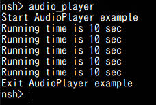
The log is displayed and the audio is played back.
If an error occurs, refer to Error Information of Audio SubSystem.
4.1.3. Appendix : Customize audio signal process
|
So far, you could run the audio_player application with this tutorial. From here on, it explains about optional function which add custom signal process. |
In AudioPlayer sample, you can perform your own signal processing on the playing audio.
If you would like to do this, you need to enable [Use postprocess] in the config menu.
-
Enable Postprocess.
Open the config menu.
tools/cofig.py -mCheck
[Use Postprocess].[Examples] [Audio player example] [Use Postprocess] <= YFor more information on Postprocess, please refer to SDK Developer Guide Set preprocess. -
Do builds
makeWhen build completed successfully,
POSTPROCbinary file will be generated underspresense/examples/audio_player/worker/.
Please put this file on/mnt/sd0/BIN(If you read SD card on PC, it’sBIN/).In this sample application, POSTPROCincludes a simple RCfilter by default.
If you want to customize your own signal processing etc, please refer to here.Please playback audio files with Postprocess Enable/Disable, and check difference. Refer How to playback.
== About customizing DSP binary (POSTPROC)
This chapter shows how to customize the DSP binary (POSTPROC).
4.1.3.1. Step 1. Edit the code of POSTPROC
Describes the code structure of POSTPROC and the editing location.
The code is divided into two parts: the part to edit the user and the part provided as a framework.
user-edited code
It is a code that users should edit mainly.
It can make unique signal processing by editing these codes.
The DSP code is in the worker directory, which has the userproc directory.
The user writes signal processing only in the userproc directory, and other things basically do not need to be changed.
Since main.cpp provides startup processing and data communication control with Main CPU, do not change it.
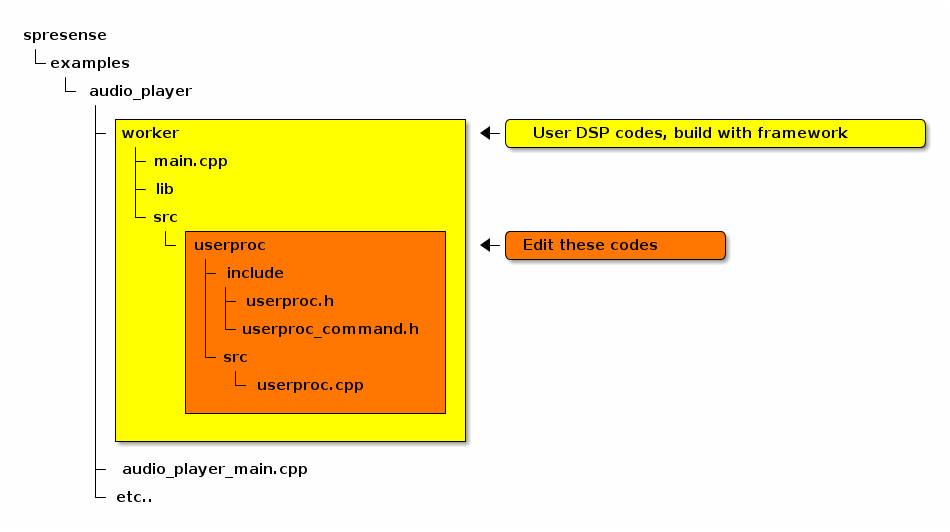
Startup processing and DSP communication processing are written. There is no need to edit.
It is a header file that defines the communication command with DSP.
Describe your necessary parameters in this file.
The header file of user code.
The source file of user code.
Write or call signal processing to this file.
APIs are provided for user code
userproc.cpp provides a framework for Init , Exec , Flush , Set commands.
The user code can support the processing in DSP by writing the unique contents.
Describes the process that the user should write.
(* By default, an RC filter is included as a sample.)
This framework assumed that the state transition inside DSP like in the figure below.
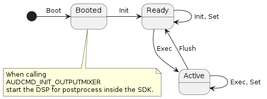
Program the process by each command as following flow.
-
DSP starts when AUDCMD_INIT_OUTPUTMIXER is called.
-
Set necessary parameters (number of channels, bit length, etc.) with the
Initcommand. -
When recording starts, the captured audio data is periodically sent to the DSP with the
Execcommand, so it can do a unique filter processing. -
If you want to change DSP internal parameters at any time, you can use
Setcommand .The execution timing of this command is in the order of command reception includingExec. -
When recording stop, the
Flushcommand is sent after the last audio data onExec, so if termination processing is necessary, the processing is performed here.
The data types used by each function are described in userproc_command.h , and the contents can be freely written.
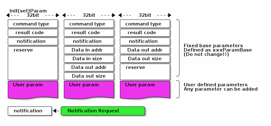
The format of each command is as shown below.
The minimum required parameters are placed in the top white area. Please do not change these.
The part of User param (purple part)in the figure below in userproc_command.h , you should define your parameters.
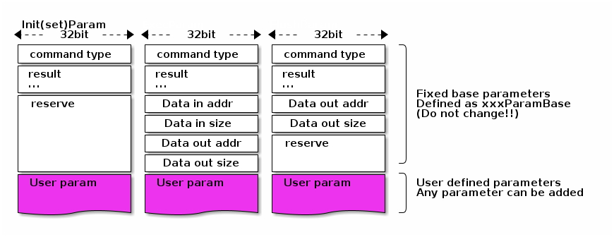
Each command is discribed in the following.
struct InitParam : public CustomprocCommand::CmdBase-
Parameter for
Initprocessing.
All parameter defined byreserved, so you will change them to necessary parameters such as the number of channels and bit length.
struct ExecParam : public CustomprocCommand::CmdBase-
Parameter for
Execprocessing.
The address and size of audio data is defined inCustomprocCommand::ExecParamBasefrom which it is inherited as inExecParamin the figure above.
For details, seesdk/modules/include/audio/dsp_framework/customproc_command_base.h.
struct FlushParam : public CustomprocCommand::CmdBase-
Parameter for
Flushprocessing.
The address and size of audio data is defined inCustomprocCommand::FlushParamBasefrom which it is inherited as inExecParamin the figure above.
For details, seesdk/modules/include/audio/dsp_framework/customproc_command_base.h.
struct SetParam : public CustomprocCommand::CmdBase-
Parameter for
Setprocessing.
Define various dynamically changed parameters. By default, RC filter On/Off and coefficients are defined as sample.
The following functions are written in userproc.cpp . The contents can be written freely.
Processing is performed according to each command definition.
void UserProc::init(InitParam *)-
Write your initialize processing according to InitParam.
It is executed by AUDCMD_INITMPP command from application code.
(Nothing is done by default)
void UserProc::exec(ExecParam *)-
Write your signal processing according to ExecParam. When you start recording, it will be called periodically from the SDK.
1 frame is 640 samples when recording setup is LPCM, 1152 for MP3 (but 1728 at 16 kHz) samples.
Get data from the input data address, do your signal processing, and write to the output data address. (RC filtering is written by default)
void UserProc::flush(FlushParam *)-
Write the flush (termination) process according to FlushParam.
when recording stops, it will be called only once from the SDK.
For example, If it is delay filter like IIR or FIR filter,flushmay be needed as filer clear.
If there is data to be output, write to the output data address.
(Nothing is done by default)
void UserProc::set(SetParam *)-
Write the set (change parameter) process according to SetParam.
It is executed by AUDCMD_SETMPPPARAM command from application code.
(By default, the RC filter coefficient is set.)
4.1.3.2. Step 2. Build POSTPROC binary
If you enable Postprocess in configuration, POSTPROC binary will be created automatically when this application is built.
The path created is POSTPROC under spresense/examples/audio_player/worker .
Put this in the /mnt/sd0/BIN ( \BIN viewed from the PC) folder on the SD card.
4.2. Sample application of Audio Recorder
This chapter shows the operation procedure of the sample application of Audio Recorder.
4.2.1. Build & Flash
Here shows the build process by using command line.
-
Move to the
sdkdirectory:Run
build-env.shscript provides tab keyword complementation ofconfig.pytool.cd spresense/sdk source tools/build-env.sh
-
Configure and build SDK.
Set
examples/audio_recorderas argument ofconfig.pyand execute configuration. When build succeeded,nuttx.spkbinary file will be generated undersdkdirectory.tools/config.py examples/audio_recorder make
-
Load
nuttx.spkto Spresense board.In this case, serial port is
/dev/ttyUSB0and baudrate is500000bps, both are set.
This parameter should be set to fit to your environment.tools/flash.sh -c /dev/ttyUSB0 -b 500000 nuttx.spk -
For Audio Recorder, it is necessary to load the DSP binary for encoding. You can choose to place the DSP binary on either an SD card or SPI-Flash. Here is how to load from the SD card.
Specify the path of DSP binary in the application code. In
audio_recorder_main.cxx, it is specified byDSPBIN_PATH.#define DSPBIN_PATH "/mnt/sd0/BIN"This code shows that the SD card is selected.
If you would like to use SPI-flash, please specify /mnt/spif/BIN.When you read SD card on PC,
/mnt/sd0/BINwill appear asBIN/under the root directory.
Create this directory and place the DSP for the required codec here.When you would like to encode MP3 files,
selectMP3ENCfile which is placed underspresense/sdk/modules/audio/dsp/The combinations of Codec type and DSP binary for other encoding are shown in the table below.
Codec DSP Binary MP3
MP3ENC
LPCM
SRC
4.2.2. Operation check of Audio Recorder
When this nuttx.spk is loaded to the Spresense board, the Audio recorder program can be executable.
Open the serial terminal as you did in the Hello sample.
minicom -D /dev/ttyUSB0 -b 115200 -s
When you run the audio_recorder app that was builtin,
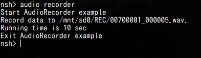
The log is displayed and the audio is recording.
The recorded audio can be played back on a PC. At that time, there is an audio file in REC/ under the SD card root directory.
In audio_recorder_main.cxx, the record file path is RECFILE_ROOTPATH , please change the application code as needed.
#define RECFILE_ROOTPATH "/mnt/sd0/REC"+
This code shows that the audio data will be recorded in REC/ directory on the SD card.
+
If an error occurs, refer to Error Information of Audio SubSystem.
4.2.3. Appendix : Customize audio signal process
|
So far, you could run the audio_recorder application with this tutorial. From here on, it explains about optional function which add custom signal process. |
In AudioRecorder sample, you can perform your own signal processing on the recorded audio.
If you would like to do this, you need to enable [Use preprocess] in the config menu.
-
Enable Preprocess.
Open the config menu.
tools/cofig.py -mCheck
[Use preprocess].[Examples] [Audio recorder example] [Use preprocess] <= YFor more information on Preprocess, please refer to SDK Developer Guide Set preprocess. -
Do builds
makeWhen build completed successfully,
PREPROCbinary file will be generated underspresense/examples/audio_recorder/worker/src.
Please put this file on/mnt/sd0/BIN(If you read SD card on PC, it’sBIN/).In this sample application, PREPROCincludes a simple RCfilter by default.
If you want to customize your own signal processing etc, please refer to here.Please playback audio files which are recorded by Preprocess Enable/Disable, and check difference. Refer How to record and playback.
== About customizing DSP binary (PREPROC)
this chapter shows how to customize the DSP binary (PREPROC).
4.2.3.1. Step 1. Edit the code of PREPROC
Describes the code structure of PREPROC and the editing location.
The code is divided into two parts: the part to edit the user and the part provided as a framework.
user-edited code
It is a code that users should edit mainly.
It can make unique signal processing by editing these codes.+
The DSP code is in the worker directory, which has the userproc directory.
The user writes signal processing only in the userproc directory, and other things basically do not need to be changed.
Since main.cpp provides startup processing and data communication control with Main CPU, do not change it.

Startup processing and DSP communication processing are written. There is no need to edit.
It is a header file that defines the communication command with DSP.
Describe your necessary parameters in this file.
The header file of user code.
The source file of user code.
Write or call signal processing to this file.
APIs are provided for user code
userproc.cpp provides a framework for Init , Exec , Flush , Set commands.
The user code can support the processing in DSP by writing the unique contents.
Describes the process that the user should write.
(* By default, an RC filter is included as a sample.)
This framework assumed that the state transition inside DSP like in the figure below.
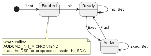
Program the process by each command as following flow.
-
DSP starts when AUDCMD_INIT_MICFRONTEND is called.
-
Set necessary parameters (number of channels, bit length, etc.) with the
Initcommand. -
When recording starts, the captured audio data is periodically sent to the DSP with the
Execcommand, so it can do a unique filter processing. -
If you want to change DSP internal parameters at any time, you can use
Setcommand .The execution timing of this command is in the order of command reception includingExec. -
When recording stop, the
Flushcommand is sent after the last audio data onExec, so if termination processing is necessary, the processing is performed here.
The data types used by each function are described in userproc_command.h , and the contents can be freely written.
The format of each command is as shown below.
The minimum required parameters are placed in the top white area. Please do not change these.
The part of User param (purple part)in the figure below in userproc_command.h , you should define your parameters.
Each command is discribed in the following.
struct InitParam : public CustomprocCommand::CmdBase-
Parameter for
Initprocessing.
All parameter defined byreserved, so you will change them to necessary parameters such as the number of channels and bit length.
struct ExecParam : public CustomprocCommand::CmdBase-
Parameter for
Execprocessing.
The address and size of audio data is defined inCustomprocCommand::ExecParamBasefrom which it is inherited as inExecParamin the figure above.
For details, seesdk/modules/include/audio/dsp_framework/customproc_command_base.h.
struct FlushParam : public CustomprocCommand::CmdBase-
Parameter for
Flushprocessing.
The address and size of audio data is defined inCustomprocCommand::FlushParamBasefrom which it is inherited as inExecParamin the figure above.
For details, seesdk/modules/include/audio/dsp_framework/customproc_command_base.h.
struct SetParam : public CustomprocCommand::CmdBase-
Parameter for
Setprocessing.
Define various dynamically changed parameters. By default, RC filter On/Off and coefficients are defined as sample.
The following functions are written in userproc.cpp . The contents can be written freely.
Processing is performed according to each command definition.
void UserProc::init(InitParam *)-
Write your initialize processing according to InitParam.
It is executed by AUDCMD_INIT_PREPROCESS_DSP command from application code.
(Nothing is done by default)
void UserProc::exec(ExecParam *)-
Write your signal processing according to ExecParam. When you start recording, it will be called periodically from the SDK.
1 frame is 768 samples when recording setup is LPCM, 1152 for MP3 (but 1728 at 16 kHz) samples.
Get data from the input data address, do your signal processing, and write to the output data address. (RC filtering is written by default)
void UserProc::flush(FlushParam *)-
Write the flush (termination) process according to FlushParam.
when recording stops, it will be called only once from the SDK.
For example, If it is delay filter like IIR or FIR filter,flushmay be needed as filer clear.
If there is data to be output, write to the output data address.
(Nothing is done by default)
void UserProc::set(SetParam *)-
Write the set (change parameter) process according to SetParam.
It is executed by AUDCMD_SET_PREPROCESS_DSP command from application code.
(By default, the RC filter coefficient is set.)
4.2.3.2. Step 2. Build PREPROC binary
If you enable Preprocess in configuration, PREPROC binary will be created automatically when this application is built.
The path created is PREPROC under spresense/examples/audio_recorder/worker/src .
Put this in the /mnt/sd0/BIN ( \BIN viewed from the PC) folder on the SD card.
4.3. Sample application of Audio Recognizer
This chapter shows the operation procedure of the sample application of Audio Recognizer.
4.3.1. Build & Flash
Here shows the build process by using command line.
-
Move to the
sdkdirectory:Run
build-env.shscript provides tab keyword complementation ofconfig.pytool.cd spresense/sdk source tools/build-env.sh
-
Configure and build SDK.
Set
examples/audio_recognizeras argument ofconfig.pyand execute configuration. When build succeeded,nuttx.spkbinary file will be generated undersdkdirectory.tools/config.py examples/audio_recognizer make
-
Load
nuttx.spkto Spresense board.In this case, serial port is
/dev/ttyUSB0and baudrate is500000bps, both are set.
This parameter should be set to fit to your environment.tools/flash.sh -c /dev/ttyUSB0 -b 500000 nuttx.spk -
For Audio Recognizer, it is necessary to load the DSP binary for recognizing. You can choose to place the DSP binary on either an SD card or SPI-Flash. Here is how to load from the SD card, put it to
/mnt/sd0/BIN.When you read SD card on PC,
/mnt/sd0/BINwill appear asBIN/under the root directory.
Create this directory and place the DSP for the recognizer binary here.This application uses recognizer DSP binary which is costumed by user.
The binaryRCGPROCwill be generated onspresense/examples/audio_recognizer/worker_recognizer/.
If you would like to custom recognizing process, please refer How to custom RecognizerPROC.== Operation check of Audio Recognizer
When this nuttx.spk is loaded to the Spresense board, the Audio Recognizer program can be executable.
Open the serial terminal as you did in the Hello sample.
minicom -D /dev/ttyUSB0 -b 115200 -s
When you run the audio_recognizer app that was builtin,

The log is displayed and the audio is recognize.
The recognition result is received by callback function in application code audio_recognizer_main.cpp .
The parameter structure depends on RecognizerDSP. Please refer RecognizerPROC.
Result data will be received with MemoryHandle, therefore, you can get data by accessing to the address.
static void recognizer_find_callback(AsRecognitionInfo info)
{
  /* Get Recognition result */

  MyRecognizerResultFormat *result =
    static_cast<MyRecognizerResultFormat *>(info.getVa())

  /* Print result */
  ...
  printf("Data size %d byte\n", info.size);
  printf("Data1 : %x, Data2 : %x\n", result->data1, result->data2);
  ...
}
+ If an error occurs, refer to Error Information of Audio SubSystem.
4.3.2. Appendix : Custom audio signal process
|
So far, you could run the audio_recognizer application with this tutorial. From here on, it explains about optional function which add custom signal process. |
A captured audio data is 48kHz or 192kHz, and bit width is 16bit or 32bit.
In AudioRecognizer sample, you can perform your own signal processing to fit to input of recognition library.
If you want to do this you need to enable [Use preprocess] in the config menu.
-
Enable Preprocess.
Open the config menu.
tools/cofig.py -mCheck
[Use preprocess].[Examples] [Audio recognizer example] [Use preprocess] <= YFor more information on Preprocess, please refer to SDK Developer Guide Set preprocess. -
Do builds
makeWhen build completed successfully,
PREPROCbinary file will be generated underspresense/examples/audio_recognizer/worker/src.
Please put this file on/mnt/sd0/BIN(If you read SD card on PC, it’sBIN/).In this sample application, PREPROCincludes a simple RCfilter by default.
If you want to customize your own signal processing etc, please refer to here.== About customizing of DSP binary
The audio_recognizer example uses two DSP binaries. For preprocess ( PREPROC ), and recognizer ( RCGPROC ).
this chapter shows how to customize the DSP binary.
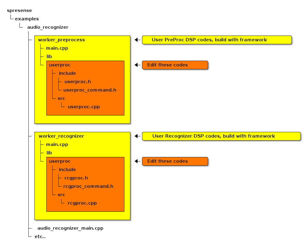
4.3.2.1. Step 1. Edit the code of PREPROC, RCGPROC
Describes the code structure of PREPROC , RCGPROC and the editing location.
The code is divided into two parts: the part to edit the user and the part provided as a framework.
User-edited code
It is a code that users should edit mainly.
It can make unique signal processing by editing these codes.+
The DSP code is in the worker_preprocess and worker_recognizer directory, which has the userproc directory.
The user writes signal processing only in the userproc directory, and other things basically do not need to be changed.
Since main.cpp provides startup processing and data communication control with Main CPU, do not change it.
Startup processing and DSP communication processing are written. There is no need to edit.
It is a header file that defines the communication command with DSP.
Describe your necessary parameters in this file.
The header file of user code.
The source file of user code.
Write or call signal processing to this file.
The header file which defines communication command with Recognition DSP. Describe your necessary parameters in this file.
The header file of Recognition DSP user code.
The source file of Recognition DSP user code.
Write or call signal processing to this file.
APIs are provided for user code
userproc.cpp, rcgproc.cpp provides a framework for Init , Exec , Flush , Set commands.
The user code can support the processing in DSP by writing the unique contents.
Describes the process that the user should write.
(* By default, an RC filter is included as a PREPROC sample.)
This framework assumed that the state transition inside DSP like in the figure below.
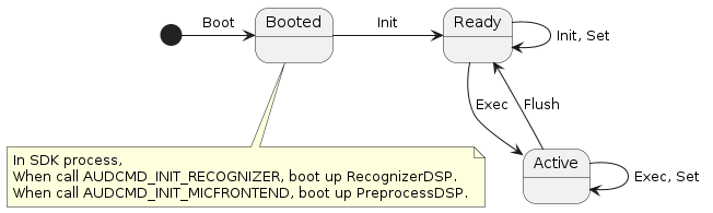
Program the process by each command as following flow.
-
DSP starts when AUDCMD_INIT_RECOGNIZER is called.
-
Set necessary parameters (number of channels, bit length, etc.) with the
Initcommand. -
When recognizing starts, the captured audio data is periodically sent to the DSP with the
Execcommand, so it can do a unique recognition processing. -
If you want to change DSP internal parameters at any time, you can use
Setcommand .The execution timing of this command is in the order of command reception includingExec. -
When recognizing stop, the
Flushcommand is sent after the last audio data onExec, so if termination processing is necessary, the processing is performed here.
The data types used by each function are described in userproc_command.h (for PREPROC) and rcgproc_command.h (for RCGPROC), and the contents can be freely written.
The format of each command is as shown below, and it has no difference between PREPROC and RCGPROC .
The minimum required parameters are placed in the top white area. Please do not change these.
The part of User param (purple part)in the figure below in userproc_command.h , you should define your parameters.
notification is a notification flag of Exec command. When you set it to except zero, result is notified to application.
For examples, you can request a reply from recognizer only when recognized result is changed.
Each command is described in the following.
struct InitRcgParam : public CustomprocCommand::CmdBase-
Parameter for
Initprocessing.
Number of channels and bit width is defined as default. Please change required parameter.
struct ExecRcgParam : public CustomprocCommand::CmdBase-
Parameter for
Execprocessing.
The address and size of audio data is defined inCustomprocCommand::ExecParamBasefrom which it is inherited as inExecParamin the figure above.
For details, seesdk/modules/include/audio/dsp_framework/customproc_command_base.h.
struct FlushParam : public CustomprocCommand::CmdBase-
Parameter for
Flushprocessing.
The address and size of audio data is defined inCustomprocCommand::FlushParamBasefrom which it is inherited as inExecParamin the figure above.
For details, seesdk/modules/include/audio/dsp_framework/customproc_command_base.h.
struct SetParam : public CustomprocCommand::CmdBase-
Parameter for
Setprocessing.
Define various dynamically changed parameters. As default, flag of enable/disable recognition is defined.
The following functions are written in rcgproc.cpp . The contents can be written freely.
Processing is performed according to each command definition.
void RcgProc::init(InitRcgParam *)-
Write your initialize processing according to InitRcgParam.
It is executed by AUDCMD_INIT_RECOGNIZER_DSP command from application code.
(Nothing is done by default)
void RcgProc::exec(ExecRcgParam *)-
Write your signal processing according to ExecParam. When you start recognizer, it will be called periodically from the SDK.
At this sample application, 1 frame is 320 samples. (You can change this value in application code).
Get data from the input data address, do your recognizer processing, and write to the output data address. (As default, output max/min/average value of audio frame.)
void RcgProc::flush(FlushRcgParam *)-
Write the flush (termination) process according to FlushParam.
when recognizer stops, it will be called only once from the SDK.
For example, If recognize process has a delay, doflushto flush a delayed data after last frame.
If there is data to be output, write to the output data address.
(Nothing is done by default)
void RcgProc::set(SetRcgParam *)-
Write the set (change parameter) process according to SetParam.
It is executed by AUDCMD_SET_RECOGNIZER_DSP command from application code.
(By default, enable flag of recognition process is set.)
4.3.2.2. Step 2. Build PREPROC, RCGPROC binary
If you enable Preprocess in configuration, PREPROC binary will be created automatically when this application is built.
The PREPROC will be generated under worker_preprocess , and the RCGPROC will be generated under worker_recognizer .
Put them in to the /mnt/sd0/BIN ( \BIN viewed from the PC) folder on the SD card.
5. TensorFlow Tutorials
5.1. TFLMRT Sample Application
5.1.1. Overview
TensorFlow Lite for Microcontrollers (TFLM) is a version of Google’s TensorFlow end-to-end open source platform for machine learning. TensorFlow LM is designed to run machine learning models on microcontrollers and other devices as it only uses a few kilobytes of memory.
The TFLM Runtime (TFLMRT) library is the runtime library for TFLM. The TFLMRT library can perform recognition processing using the Deep Neural Network (DNN) using trained models by TensorFlow.
This sample application describes how to train a TFLM model for handwritten-number recognition that runs on Spresense.
Spresense SDK versions 2.1.0 and later support TensorFlow LM.
5.1.2. Train a TensorFlow Lite model
Here, we show how to train a TensorFlow model using classification of MNIST dataset of images of handwritten numbers and convert the model to a TensorFlow Lite model.
The two stages are:
-
Train your own TensorFlow model. Sample python code to train a model using an MNIST dataset.
-
Convert to a TensorFlow Lite model. How to use the TensorFlow Lite converter to create the reduced-size model.
5.1.2.1. Train your own TensorFlow model
The dataset used for classification and training the TensorFlow model is from the MNINST database of handwriting images. TensorFlow can download and import the MNINST dataset directly from an API. The first stage uses python code to train the model.
The trained model created by python code below takes one image of size 28 x 28 and outputs 10 arrays. These 10 arrays correspond to the numbers recognized by the index, and the probability of each number is output in the array. For example, at the head of an array (index 0), the probability that the input image is the number "0" is output.
# Import TensorFlow
import tensorflow as tf

# Import TensorFlow Datasets
import tensorflow_datasets as tfds

# Helper libraries
import math

dataset, metadata = tfds.load('mnist', as_supervised=True, with_info=True)
train_dataset, test_dataset = dataset['train'], dataset['test']

num_train_examples = metadata.splits['train'].num_examples
num_test_examples = metadata.splits['test'].num_examples

def normalize(images, labels):
  images = tf.cast(images, tf.float32)
  images /= 255
  return images, labels

# The map function applies the normalize function to each element in the train
# and test datasets
train_dataset =  train_dataset.map(normalize)
test_dataset  =  test_dataset.map(normalize)

# The first time you use the dataset, the images will be loaded from disk
# Caching will keep them in memory, making training faster
train_dataset =  train_dataset.cache()
test_dataset  =  test_dataset.cache()

model = tf.keras.Sequential([
    tf.keras.layers.Conv2D(16, kernel_size=(7, 7), strides=(1, 1), activation='relu', input_shape=(28, 28, 1), padding="valid"),
    tf.keras.layers.MaxPooling2D(pool_size=(2, 2), strides=(2, 2), padding='valid'),
    tf.keras.layers.Conv2D(30, kernel_size=(3, 3), strides=(1, 1), activation='tanh', padding='valid'),
    tf.keras.layers.MaxPooling2D(pool_size=(2, 2), strides=(2, 2), padding='valid'),
    tf.keras.layers.Flatten(),
    tf.keras.layers.Dense(150, activation='relu'),
    tf.keras.layers.Dense(10, activation='softmax'),
])

model.compile(optimizer='adam',
              loss=tf.keras.losses.SparseCategoricalCrossentropy(),
              metrics=['accuracy'])

BATCH_SIZE = 32
train_dataset = train_dataset.cache().repeat().shuffle(num_train_examples).batch(BATCH_SIZE)
test_dataset = test_dataset.cache().batch(BATCH_SIZE)

model.fit(train_dataset, epochs=10, steps_per_epoch=math.ceil(num_train_examples/BATCH_SIZE))
5.1.2.2. Convert to a TensorFlow Lite model
We now need to convert the TensorFlow model to a TFLM mode so it can be run on Spresense.
To convert a trained TensorFlow model to run on Spresense, use the TensorFlow Lite converter Python API.
This converts the model into a FlatBuffer, reducing the model size, and modify it to use TensorFlow Lite operations.
for images, labels in train_dataset.take(1):
    numpy_images = images.numpy()
    numpy_labels = labels.numpy()

def representative_data_gen():
  for input_value in tf.data.Dataset.from_tensor_slices(numpy_images).batch(1).take(100):
    yield [input_value]

converter = tf.lite.TFLiteConverter.from_keras_model(model)
converter.optimizations = [tf.lite.Optimize.DEFAULT]
converter.representative_dataset = representative_data_gen
converter.target_spec.supported_ops = [tf.lite.OpsSet.TFLITE_BUILTINS_INT8]
converter.inference_input_type = tf.int8
converter.inference_output_type = tf.int8

tflite_model_quant = converter.convert()

# Save the model to disk
open('model.tflite', "wb").write(tflite_model_quant)
For more information about building and converting TensorFlow models, see the following guide from the TFLM website, which describes how to create and convert TensorFlow models to run on microcontrollers.
5.1.3. Build procedure
This is the build procedure via the command line. When you use IDE, refer to the explanation of the following configuration.
-
Change directory to
sdkIf you do source
build-env.shscript, you can use the tab completion of theconfig.pytool.cd spresense/sdk source tools/build-env.sh
-
SDK configuration and building
Execute the configuration by specifying
examples/tflmrt_lenetas an argument ofconfig.py. If the build is successful, anuttx.spkfile will be created under thesdkdirectory.tools/config.py examples/tflmrt_lenet make
-
Flashing
nuttx.spkinto Spresense boardIn this case, the serial port is
/dev/ttyUSB0, and the baudrate of the uploading speed is500000bps. Please change according to your environment.tools/flash.sh -c /dev/ttyUSB0 -b 500000 nuttx.spk
5.1.4. Operation check
Now you can open the serial terminal, and run the tflmrt_lenet command.
-
Open the serial terminal.
This is an example of using a minicom terminal with
/dev/ttyUSB0as the serial port and115200as the baudrate.minicom -D /dev/ttyUSB0 -b 115200 -
Type
tflmrt_lenetcommand on NuttShell promptThe usage of
tflmrt_lenetcommand is shown below:Usage: tflmrt_lenet [-s] [tflite] [pgm] tflmrt_lenet instantiates a neural network defined by tflite model (default: built-in TensorFlow Lite model), and feeds an image (default: built-in test image). Options include: [-s] = Skip image normalization before feeding into the network. If no -s option is given, image data is divided by 255.0. [tflite] = Path to TF Lite model, if not given or "default", then use built-in TensorFlow Lite model. [pgm] = Path to pgm image, if not given use built-in test image (0).
Example 1. Using your own model:-
Put your own model on the SD card.
-
Use the
tflmrt_lenetcommand along with the path to this model:tflmrt_lenet /mnt/sd0/model.tflite
-
This example application prints a 1D-array which TensorFlow Lite model outputs as output[0-9].
For example, execute tflmrt_lenet as shown below.
Then, you can refer to output[0-9] as probabilities that each digit is drawn.
In this example, since you feed built-in test image (0), the corresponding output[0] should be almost 1.0.
nsh> tflmrt_lenet
Load built-in model
Load built-in test image
Image Normalization (1.0/255.0): enabled
start tflm_runtime_forward()
output[0]=0.996093
output[1]=0.000000
output[2]=0.000000
output[3]=0.000000
output[4]=0.000000
output[5]=0.000000
output[6]=0.000000
output[7]=0.000000
output[8]=0.000000
output[9]=0.000000
5.2. TensorFlow Lite for Microcontrollers: code examples
This tutorial describes how to execute the sample code on Spresense equipment. It consists of three TensorFlow sample code examples that run using Spresense SDK v2.1.0.
The three TensorFlow LM code examples are called:
-
hello_world
-
micro_speech
-
person_detection
5.2.1. Spresense equipment required
The equipment required to run each example is shown in the following table:
| Example name | Equipment | Picture |
|---|---|---|
hello_world |
1. Spresense Main Board |
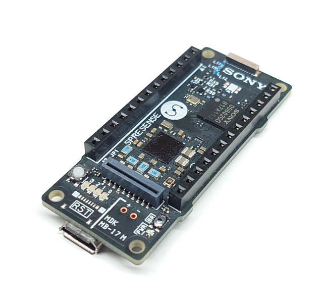
|
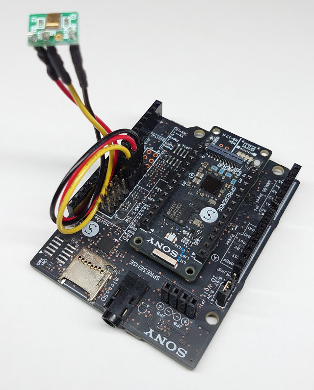
micro_speech |
1. Spresense Main Board |
|
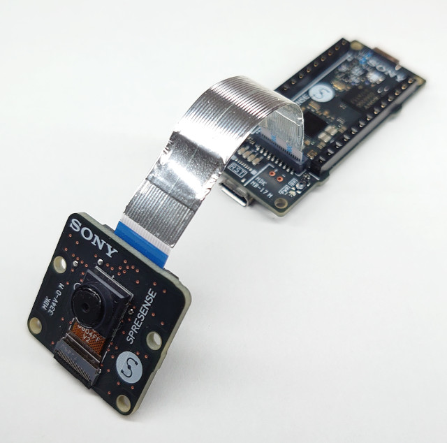
person_detection |
1. Spresense Main Board |
|
5.2.2. Overview of TensorFlow LM on Spresense SDK
If you enable TensorFlow LM in Kconfig in Spresense SDK, the source code will be downloaded during the build process, and built as a library archive.
If specified in Kconfig, the TensorFlow LM source code will be downloaded to externals/tensorflow after the build is executed.
The build uses the same build system provided by TensorFlow LM.
|
For SDK v2.1.0, the Git SHA-1 of the TensorFlow LM to download is "372e7eef27e03adabceb4c7ca41d366776573a731". |
When you select a TensorFlow LM example in the Spresense Kconfig, the corresponding example in the TensorFlow LM will also be built together as a library.
Each TensorFlow LM example is wrapped into a command called tf_example so that it can be run as a command in NuttShell, the NuttX command used by the Spresense SDK.
Since the setup() and loop() functions are implemented for the TensorFlow LM example to be run on Arduino, these functions are called in the tf_example.
The relationship between Spresense SDK, TensorFlow LM, and the code examples are shown in the following diagram:
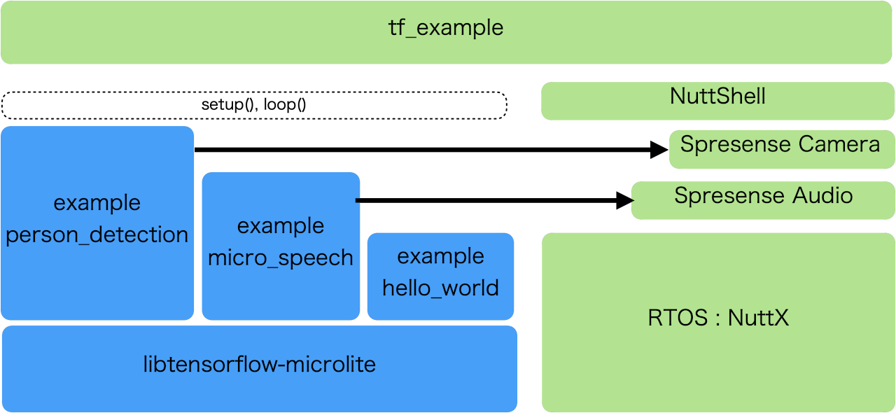
The blue boxes are provided by TensorFlow LM, and the green boxes are provided by Spresense SDK.
5.2.3. Directory location of sample code
The source code for each example is contained in the directories as follows:
-
tf_example NuttShell command:
-
examples/tf_example
-
-
Code for using Spresense’s camera and Audio functions
-
externals/tensorflow
-
-
hello_world of TensorFlow LM:
-
externals/tensorflow/tensorflow-{Git SHA-1}/tensorflow/lite/micro/examples/hello_world
-
-
micro_speech of TensorFlow LM:
-
externals/tensorflow/tensorflow-{Git SHA-1}/tensorflow/lite/micro/examples/micro_speech
-
-
person_detection of TensorFlow LM:
-
externals/tensorflow/tensorflow-{Git SHA-1}/tensorflow/lite/micro/examples/person_detection
-
|
The directory tensorflow-{Git SHA-1} will download and extract when the build sequence is complete. |
5.2.4. How to build the sample code
This is the build procedure via the command line.
When you use IDE, refer to the explanation of the following configuration.
There are two steps in the build process:
-
Configuring the example
-
Executing the "make" to build the example.
|
The TensorFlow LM examples cannot be built in the Windows OS environment.
This is because the Spresense SDK build system on the Windows OS is based on MSYS2, and the TensorFlow build system does not work on MSYS2 in Windows. |
Step 1: Configuring the example
-
Change directory to
sdkIf you do source
build-env.shscript, you can use the tab completion of theconfig.pytool.cd spresense/sdk source tools/build-env.sh
-
Configuration
Execute the configuration by specifying for each example as an argument of
config.py.tools/config.py {default config name}For each example, replace {default config name} with the string shown in the Default config name column in the following table:
Example name Default config name hello_world
examples/tf_example_helloworld
micro_speech
examples/tf_example_micro_speech
person_detection
examples/tf_example_persondetect
For example, if you want to build the "micro_speech" example, the command should be:
tools/config.py examples/tf_example_micro_speech
5.2.5. How to flash the nuttx.spk
Use the following command to flash the nuttx.spk.
In this case, the serial port is /dev/ttyUSB0, and the baudrate of the uploading speed is 500000 bps.
Modify the command as required by your environment.
tools/flash.sh -c /dev/ttyUSB0 -b 500000 nuttx.spk
5.2.6. How to run the examples
-
Open the serial terminal.
Here, we use a minicom terminal with
/dev/ttyUSB0as the serial port and115200as the baudrate.minicom -D /dev/ttyUSB0 -b 115200 -
Type
tf_examplecommand on NuttShell promptnsh> tf_example
The results of the operation will be output for each example.
Example result: hello_world
The following line is displayed continuously.
x_value: xxxxxx, y_value: xxxxxxx
Example result: micro_speech
Speak "Yes" or "No" into the MEMS Mic. Any result recognized is output on the terminal as follows.
Heard unknown (xxx) @ xxxxxx
Heard yes (xxx) @ xxxxxx
Heard no (xxx) @ xxxxxx
5.2.6.1. Example result: person_detection
By pointing the camera at a person’s face or at something other than a person’s face, the results of the recognition will be displayed, as shown below.
person score:xxx no person score:xxx
Pointing the camera at a person’s face will increase the "person score", while pointing the camera at something other than a person’s face will increase the "no person score".
6. Camera Tutorials
6.1. camera sample application
In this chapter, we will discuss an example using the Spresense Camera board.
This sample is intended to give you a taste of the basic usage of Spresense Camera.
6.1.1. System Requirements
It is assumed that the following hardware is used to run this sample
-
Spresense Main Board
-
Spresense Camera Board
-
Spresense Extension Board
-
Arduino UNO LCD Connector board
-
ILI9341 2.2inch LCD
6.1.2. Source code
The source code for this example can be found under examples/camera.
The structure of the files in the directory looks like this
camera/
.
├── Kconfig
├── Make.defs
├── Makefile
├── README.txt
├── camera_bkgd.c
├── camera_bkgd.h
├── camera_fileutil.c
├── camera_fileutil.h
└── camera_main.c
The main files and folders are outlined below.
| file/folder | name |
|---|---|
camera_main.c |
The file that implements the main() function. |
camera_bkgd.c |
implementation of the utility functions to control NX, the NuttX graphics system. |
camera_fileutil.c |
The file that implements the utility functions to save the data acquired from the image sensor to a file. |
6.1.3. Build procedure
It describes the build procedure using the CLI version, but you can build this sample application in the IDE version as well by choosing the same configuration.
-
Go to the
sdkdirectory.Loading the
build-env.shscript enables the Tab completion feature of the configuration tool.cd spresense/sdk source tools/build-env.sh
-
Configuration and build.
Execute the configuration with the argument
examples/camera.
After a successful build, anuttx.spkfile is generated under thesdkfolder.make distclean tools/config.py examples/camera make
-
Write
nuttx.spkto the Spresense board.In this example, the serial port is set to /dev/ttyUSB0 and the write speed baudrate is set to 500000 bps.
tools/flash.sh -c /dev/ttyUSB0 -b 500000 nuttx.spk
6.1.4. Operation check
Open a serial terminal and run the camera command.
-
Start the serial terminal.
The following is an example using a minicom terminal. The serial port is set to /dev/ttyUSB0 and the baudrate is set to 115200 bps.
minicom -D /dev/ttyUSB0 -b 115200 -
Execute the
cameracommand from NuttShell.From the nsh> prompt, type camera and press enter to run.
nsh> camera
If it works correctly, the LCD will display the camera’s image.
Note that the default is to display 10 frames and then exit.
In order to display the camera image continuously, run the following command with 0 in the argument.nsh> camera 0
6.2. multiwebcam Sample Application
This chapter shows you how a multiwebcam sample application works. This sample shows how to use the IDY Spresense Wi-Fi Add-on Board iS110B to send a JPEG image taken by the Camera to a connected device via Wi-Fi. There are two modes in this sample.
-
one-to-one communication, using Motion JPEG over HTTP as the transfer protocol (You can monitor the camera images by accessing Spresense from your browser)
-
one to many communication mode to retrieve image data from multiple Spresense using a proprietary transfer protocol and display it in a PC app (You’ll need a special app, but you can view multiple camera images on one screen.
In both cases, Spresense acts as a server that sends the images and connects to the server from a browser or a PC tool to retrieve them.
This sample has been implemented based on the following technical elements.
-
Spresense Camera (V4L2 like I/F)
-
multi pthread programing
-
socket programing
-
Tiny HTTP server
6.2.1. Operating Environment
To run this sample, it is assumed to use the following hardware.
-
Spresense Main Board
-
Spresense Camera Board
-
IDY Wi-Fi Add-on Board iS110B
6.2.2. Source Code
The source code for this sample can be found under examples/multi_webcamera.
The structure of the files in the directory is as follows.
multi_wabcamera/
 ├── Kconfig
 ├── Make.defs
 ├── Makefile
 ├── README.txt
 ├── multiwebcam_main.c
 ├── multiwebcam_perf.h
 ├── multiwebcam_server.c
 ├── multiwebcam_server.h
 ├── multiwebcam_threads.c
 ├── multiwebcam_threads.h
 ├── multiwebcam_util.c
 ├── multiwebcam_util.h
 ├── startup_script/
 │   └── init.rc
 └── host/
     ├── ImgScaler.py
     ├── MultiCameraFrame.py
     ├── NetImgReceiver.py
     └── test_module/
The main files and folders summary is as follows.
| file/folder name | summary |
|---|---|
multiwebcam_main.c |
Sample code main processing implementation file. |
multiwebcam_server.c |
Network processing implementation files. |
multiwebcam_threads.c |
Implementation files for Thread to obtain JPEG data from the image sensor and to send the obtained JPEG data to the connected client. |
multiwebcam_util.c |
Queue implementation files for sending and receiving messages between Threads. |
startup_script/init.rc |
Sample (Template) Script for Spresense Launch. |
host/ |
PC-side sample code (Python) in the case of multi-camera mode. |
6.2.3. Source Code Description
This section describes the behavior of the source code.
The entire app is shown in the following figure
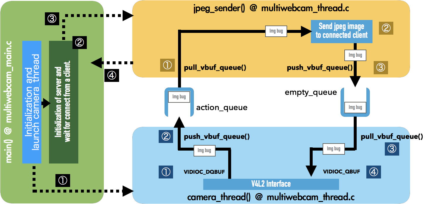
In this app, three threads, main(), camera_thread() and jpeg_sender(), work together. The following is a description of the behavior of each of these three.
6.2.3.1. main()
Main Functions.
Initialize the Spresense Video driver (including initializing the image sensor) and start camera_thread() as a Thread. (1) in the green block above
Then we create a socket as a server and call the accept() function and wait for a connection from the client. (2) in the green block above
When connected by the client, invoke jpeg_sender() as a Thread to send the JPEG. (3) in the green block above
After invoking jpeg_sender(), in main(), we wait for the jpeg_sender() Thread to exit, and when it does, we accept() again and wait for a connection from a new client. (3) in the green block above
The key steps and source code are excerpted below.
| Number in green block | file name:Line number | Code | Description |
|---|---|---|---|
① |
multiwebcam_main.c:77 |
video_initialize(VIDEO_DEV_PATH); |
Initialize video driver. |
multiwebcam_main.c:79 |
v_fd = open(VIDEO_DEV_PATH, 0); |
Open the video driver device file. |
|
multiwebcam_main.c:86 |
ret = multiwebcam_prepare_camera_buf(v_fd, V4L2_BUF_TYPE_STILL_CAPTURE, V4L2_BUF_MODE_RING, 2, &vbuffs); |
Creating a JPEG data buffer and registering it to the Video driver. |
|
multiwebcam_main.c:105 |
rsock = multiwebcam_initserver(MULTIWEBCAM_PORT_NO /* Port Number */); |
Creating the server socket. |
|
multiwebcam_main.c:109 |
cam_thd = multiwebcam_start_camerathread(v_fd); |
Generating camera_thread() Thread. |
|
② |
multiwebcam_main.c:117 |
wsock = multiwebcam_waitconnection(rsock, &client); |
Waiting for a connection from the client, specifically reading the accept() function and waiting for a connection. |
③ |
multiwebcam_main.c:122 |
jpeg_thd = multiwebcam_start_jpegsender(wsock); |
Generate jpeg_sender() Thread. |
④ |
multiwebcam_main.c:123 |
pthread_join(jpeg_thd, NULL); |
Waiting for exiting jpeg_sender() thread. |
Back to (2) after exiting the thread. |
6.2.3.2. camera_thread()
Thread for acquiring images from the image sensor.
When invoked by the main() function, issues VIDIOC_DQBUF to the Video driver to retrieve the captured data. (1) in the blue block above.
Then, check if the jpeg_sender() Thread is running, and if so, send the acquired JPEG data to action_queue to pass it to the jpeg_sender() Thread. (2) in the blue block above.
Get an empty buffer from empty_queue() after sending the data.(3) in the blue block above.
Then set an empty buffer in the Video driver with VIDIOC_QBUF and wait for the JPEG data to be acquired from the image sensor. (4) in the blue block above.
Now repeat this.
The key steps and source code are excerpted below.
| Number in blue block | File name:Line number | Code | Description |
|---|---|---|---|
① |
multiwebcam_thread.c:72 |
multiwebcam_get_picture_buf(v_fd, &buf, V4L2_BUF_TYPE_STILL_CAPTURE); |
Get a JPEG image from the Video driver. |
multiwebcam_thread.c:78 |
while (!is_run){ … } |
Waiting for jpeg_sender() thread wakeup. |
|
② |
multiwebcam_thread.c:93 |
multiwebcam_push_action(multiwebcam_get_vbuffer(&buf)); |
Push the read JPEG data to action_queue. |
③ |
multiwebcam_thread.c:98 |
while (multiwebcam_is_emptyqueue_empty() && is_run){ … } |
Wait until the used up buffer is pushed to empty_queue. |
multiwebcam_thread.c:98 |
for (vbuf = multiwebcam_pull_empty(); vbuf != NULL; vbuf = multiwebcam_pull_empty()){ … } |
All buffers in empty_queue are re-registered in the Video driver. |
|
When you finish re-registering to the Video driver, return to (1). |
6.2.3.3. jpeg_sender()
Thread to run to send JPEG data once a connection is established from the client.
Once the connection from the client is established, it will be started from the main() Thread and set the is_run variable to true to tell camera_thread() that it has been started.
Then wait for camera_thread() to push the JPEG data to action_queue, and then retrieve it when pushed. (1) in the yellow block above.
Once the data is retrieved, send the JPEG data to the client according to the current selected protocol (Motion JPEG over HTTP, or proprietary transfer protocol). (2) in the yellow block above.
After the transmission is complete, send a buffer of used JPEG data to empty_queue. (3) in yellow block above.
If we lose the connection with the client, we set is_run to false to tell camera_thread() to exit, and then exit the Thread. (Dotted line (4) from the yellow block to the green block in the above figure)
The key steps and source code are excerpted below.
| Number in yellow block | File name:Line number | Code | Description |
|---|---|---|---|
multiwebcam_thread.c:145 |
is_run = true; |
Tell the camera_thread() Thread to start. |
|
multiwebcam_thread.c:149 |
multiwabcam_sendheader(sock); |
Send data that should be sent only once at the beginning of the connection. |
|
① |
multiwebcam_thread.c:155 |
while(multiwebcam_is_actionqueue_empty()){ … } |
Wait while action_queue is empty (until camera_thread() pushes the JPEG). |
multiwebcam_thread.c:159 |
buf = multiwebcam_pull_action(); |
Extract the JPEG data from action_queue. |
|
② |
multiwebcam_thread.c:162 |
ret = multiwebcam_sendframe(sock, (char *)buf→start, (int)buf→jpg_len); |
Send the retrieved data to the client. |
③ |
multiwebcam_thread.c:166 |
multiwebcam_push_empty(buf); |
Push the finished sending buffer to empty_queue. |
After pushing it to empty_queue, return to ①. |
6.2.4. Build and execution instructions (for one-to-one Motion JPEG over HTTP mode)
This sample code exists in two modes: one mode to send it in one-to-one Motion JPEG over HTTP, and another mode to send it in many-to-one proprietary transfer protocol.
This section describes the case of letting them communicate using one-to-one Motion JPEG over HTTP.
If you want to communicate in many-to-one proprietary transfer protocol mode, see Build and run instructions (many-to-one proprietary transfer protocol mode).
6.2.4.1. How to build it
This article describes the build procedure using the CLI version, but you can build this sample application in the IDE version as well by choosing the same configuration.
-
Go to the
sdkdirectoryLoading the
build-env.shscript enables the Tab completion feature of the configuration tool.cd spresense/sdk source tools/build-env.sh
-
Configure and build
Execute the configuration with the argument
examples/multiwebcam.
When the build succeeds, anuttx.spkfile is generated directly under thesdkfolder.make distclean tools/config.py examples/multiwebcam make
-
Flash
nuttx.spkinto Spresense boardAfter the build is successfully completed, a file named nuttx.spk will be generated in the sdk folder, which will be written to the target Spresense. In this example, the serial port is set to /dev/ttyUSB0 and the write speed baudrate is set to 500000 bps.
tools/flash.sh -c /dev/ttyUSB0 -b 500000 nuttx.spk
6.2.4.2. Operation check
To launch the sample app on the device side, open a serial terminal, connect to Wi-Fi and run the multiwebcam command.
-
Launch serial terminal
First, from the terminal software, enter NuttShell by connecting to the Spresense serial port.
In the example below, the serial port connected to the target Spresense is /dev/ttyUSB0, connected with minicom with 115200 bps as baudrate.minicom -D /dev/ttyUSB0 -b 115200 -
Connect to Wi-Fi network
In the example below, we boot up Wi-Fi in AP mode, with SSID as presence_net and password as 0123456789.
Once the Wi-Fi module has been successfully launched, it will set an IP address and check it. In the example below, there is about 5 seconds of sleep before the Wi-Fi module finishes booting.
In the ifconfig command, the IP address will be assigned, as shown below.nsh> gs2200m -a 1 spresense_net 0123456789 & nsh> sleep 5 nsh> ifconfig eth0 Link encap:Ethernet HWaddr 3c:95:09:00:56:49 at UP inet addr:192.168.11.1 DRaddr:192.168.11.1 Mask:255.255.255.0In the above example, 192.168.11.1 would be the IP address of Spresense.
Note that HWaddr may vary depending on the purchased Wi-Fi module. -
Launch the application
Once the Wi-Fi setup is complete, launch the multiwebcam app.
nsh> multiwebcam
Now, the Spresense side is ready.
-
Connect to the Wi-Fi network you have created with your PC or smartphone
Next, in order to view the images from the camera in a browser, such as a PC or smartphone, first connect your PC or smartphone to the Wi-Fi network you just activated with Spresense. Connect to the Wi-Fi network with your phone or other device.
The SSID of the Wi-Fi you are connecting to will be spresense_net, which you set up earlier. In the Wi-Fi connection settings on your PC or phone, look for spresense_net and connect.
Choose WPA/WPA2 as the encryption method when connecting.
The password is 0123456789, set above. -
Connect to the Spresense camera in the browser to view Live View
Once you have successfully connected to the Wi-Fi network, you can open a browser on the connected PC or smartphone and enter the following URL in the URL input field to view the camera’s image.
http://192.168.11.1
If it works correctly, the image of the camera will be displayed on the browser.
6.2.5. Build and run instructions (many-to-one proprietary transfer protocol mode)
Then describes how to build and run it using a many-to-one proprietary protocol.
Basically, the build method is the same as Motion JPEG over HTTP.
The only difference in the build method is that in the Config menu of the Example, disable the "Http MJPEG is used" option.
The usage on the device side is almost the same, with the only difference being that the WiFi connection settings are stations instead of access points.
Now, let’s take a step-by-step description.
6.2.5.1. How to build
This section describes the build procedure using the CLI version, but you can build this sample application in the IDE version as well by choosing the same configuration.
-
Go to the
sdkdirectory.Loading the
build-env.shscript enables the Tab completion feature of the configuration tool.cd spresense/sdk source tools/build-env.sh
-
Configuration.
Execute the configuration with the argument
examples/multiwebcam.make distclean tools/config.py examples/multiwebcam
Then open the menu config with the following command.
make menuconfigAfter opening the menu, use the arrow keys to go to "Application Configuration" at the bottom of the menu and press Enter to enter the menu and then proceed to "Examples"
  "Application Configuration"
       -> "Spresense SDK"
             -> "Examples"
Once you get into Examples "[*] Multi Web Camera" Among the items checked with "[*] Http MJPEG is used" Hover over this item and uncheck it with the spacebar.

Once unchecked, hover over "<Exit>" and press enter, and then do <Exit> at the top level, you will be asked to "Do you wish to save your new configuration? Exit menuconfig.
-
Build.
Once the configuration is complete, build with the following command.
makeAfter a successful build, a
nuttx.spkfile is generated under thesdkfolder. -
Write the
nuttx.spkto the Spresense board, which should be written to thenuttx.spkfile.After the build is successfully completed, a file named nuttx.spk will be generated in the sdk folder, which will be written to the target Spresense. In this example, the serial port is set to /dev/ttyUSB0 and the write speed baudrate is set to 500000 bps.
tools/flash.sh -c /dev/ttyUSB0 -b 500000 nuttx.spk
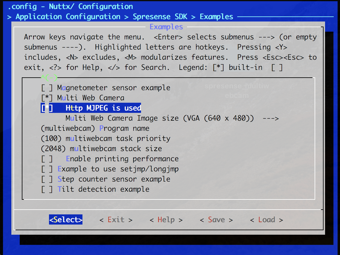
6.2.5.2. Operation check
To launch the sample app on the production side, open a serial terminal, connect to Wi-Fi and run the multiwebcam command.
-
Launch the serial terminal.
First, from the terminal software, enter NuttShell by connecting to the Spresense serial port.
In the example below, the serial port connected to the target Spresense is /dev/ttyUSB0 with minicom with the baudrate set to 115200 bps.minicom -D /dev/ttyUSB0 -b 115200 -
Wi-Fi Connection.
In the example below, we will launch Wi-Fi in STA mode, so please prepare the SSID and password of the Wi-Fi network you want to connect to beforehand, because in STA mode, you will be connecting to an existing Wi-Fi network.
In this example, the SSID is described as hogehoge and the password as hogehoge1.
Once the Wi-Fi module has been successfully launched, it will set an IP address and check it. In the example below, there is about 5 seconds of sleep before the Wi-Fi module finishes booting.
In the ifconfig command, the IP address will be assigned as follows.nsh> gs2200m hogehoge hogehoge1 & nsh> sleep 5 nsh> ifconfig eth0 Link encap:Ethernet HWaddr 3c:95:09:00:56:49 at UP inet addr:XXX.XXX.XXX.XXX.XXX DRaddr:XXX.XXX.XXX.XXX Mask:255.255.255.0As a result of ifconfig, you will see the resulting IP address connected to inet addr.
Note that HWaddr may vary depending on the purchased Wi-Fi module.
Please make a note of the IP address you get here as it will be needed in the PC app settings. -
Launch the app.
Once the Wi-Fi setup is complete, launch the multiwebcam app.
nsh> multiwebcam
Now, the Spresense side is ready.
If you are using more than one Spresense, connect to Wi-Fi and launch the multiwebcamera in the same way.
-
Launching the PC app
The PC-side app was created in Python as a reference to display images from multiple cameras. The app has been verified to work on a Linux PC.
To run, you must first install Python 2.7.
In addition, you will need the following libraries of Python, please install each of the following.-
python-wxgtk3.0
-
python-wxtools
In Linux, you can install with the following command. The following commands can be installed on Linux
sudo apt install python-wxgtk3.0 python-wxtoolsAfter installing the necessary Python libraries, the first step is to set the IP address of the Spresense to connect to. We will use the IP address that we wrote down when we launched the actual device earlier.
Go into the host/ folder and open MultiCameraFrame.py.
listed in the 183rd line of that file,servers = ( ('192.168.11.1', 10080), ('192.168.11.2', 10080), ('192.168.11.3', 10080), ('192.168.11.4', 10080) )Replace the IP address listed as 192.168.11.1 ~ 4 in the code "192.168.11.1 ~ 4" with the IP address you wrote down.
Up to four devices can be displayed, but if you don’t have four, just change it for the number of devices you have and leave the rest as they are.
As an example, if there are two devices, 10.0.0.0.5 and 10.0.0.0.8, respectively, you would configure them as follows.servers = ( ('10.0.0.5', 10080), ('10.0.0.8', 10080), ('192.168.11.3', 10080), ('192.168.11.4', 10080) )When you are done editing, you can save the file and launch the app by hitting the following command from the command prompt.
python MultiCameraFrame.pyIf launched correctly, the Window will appear on the full screen and begin to display images from the device.
Naturally, the PC must be connected to the same Wi-Fi network as the one to which the device is connected.
-
6.2.5.3. Description of the PC side app
Here is a brief description of the PC app.
First, the structure of the PC app is shown in the following figure
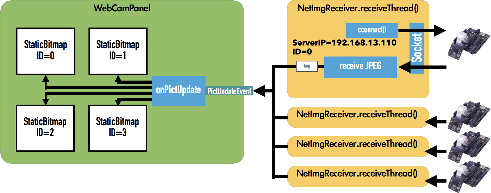
The host app utilizes wxPython as the Window programming framework to generate MultiCamFrame with a custom panel implemented in MultiCameraFrame.py: WebCamPanel.
Pass a list of IP addresses and port numbers of the Spresense to connect to its arguments.
When Frame starts, it generates a WebCamPanel, in which it generates four StaticBitmaps and pastes them into the frame, and then generates four NetImgReceivers based on the list of IP addresses and port numbers that are passed to it. Implemented in NetImgReceiver.py, it gives the IP address and port number of the server to connect to the ID number associated with the StaticBitmap.
After the NetImgReceiver is created, receiveThread() is launched as a Thread and begins parallel operations.
receiveThread() makes a connection request to the server on the Spresense device side based on the specified server IP and port number.
Once the connection is established, start receiving JPEG images.
When the reception of JPEGs is complete, it fires WebCamPanel’s PictUpdateEvent and sends the received JPEG data to WebCamPanel with the ID number.
In WebCamPanel, onPictUpdate() is called back when a PictUpdateEvent is fired. This function receives the received JPEG data and ID number, adjusts the image size and then displays the received image in StaticBitmap based on the ID number.
6.2.6. Appendix : Packet format
Here we explain the format of the packets exchanged in each mode.
6.2.6.1. Motion JPEG over HTTP
It uses "multipart/x-mixed-replace", which is defined as an HTML standard. See below for details.
https://html.spec.whatwg.org/#read-multipart-x-mixed-replace
6.2.6.2. Proprietary Protocols
Proprietary protocol will be a protocol created for the simple purpose of just sending JPEG data to a connected client.
The packets are ordered as delimiters, starting with the four-character Ascii code "SZ: ", followed by the JPEG data size (number of bytes) of 4 bytes (Little endian), and then the JPEG data for that size.
The above format can be illustrated as follows.
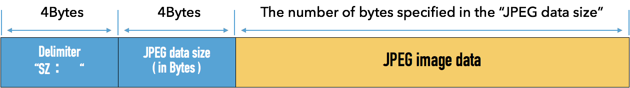
6.2.7. Tips : Auto start of spresense applications.
Commands running at the presense nsh prompt can also be executed automatically at startup.
See How to start applications automatically for more information.
7. JPEG Tutorials
7.1. JPEG decode sample application
7.1.1. Overview
This sample application is an application that decodes JPEG file and generates YUV4:2:2 format file.
7.1.2. Build procedure
This section shows the build procedure using the command line.
When building using the IDE, refer to the configuration information shown below.
-
Move to the
sdkdirectory.Loading the
build-env.shscript enables the tab completion feature of theconfig.pytool.cd spresense/sdk source tools/build-env.sh
-
Configure and build the SDK.
Execute the configuration with
examples/jpeg_decodeas an argument.tools/config.py examples/jpeg_decodeIf the build is successful, a
nuttx.spkfile will be generated directly under the` sdk` folder.make -
Write
nuttx.spkto the Spresense board.In this example, the serial port is set to
/dev/ttyUSB0and the write speed baudrate is set to` 500000` bps. Please change it according to your environment.tools/flash.sh -c /dev/ttyUSB0 -b 500000 nuttx.spk
7.1.3. Operation check
Open a serial terminal and execute the jpeg_decode command.
-
Start the serial terminal.
Here is an example of using a minicom terminal with
/dev/ttyUSB0as the serial port and` 115200` bps as the baudrate.minicom -D /dev/ttyUSB0 -b 115200 -
Run the
jpeg_decodecommand from NuttShell.The following shows how to use the jpeg_decode command.
nsh> jpeg_decode <filename>
- filename
-
Specify the full path of the JPEG file you want to decode.
Place the file specified by filename in
/mnt/spif/or/mnt/sd0/and execute it. The decoding result is generated in the same directory with the extension .YUV.
This sample application decodes the file specified by filename
and saves the decoded result in the same directory as the decoding source.
The decoding result will be the one in which the extension of the decoding source file is changed to .YUV.
The following is an example of decoding
a JPEG file called SAMPLE.JPG by executing the jpeg_decode command .
nsh> jpeg_decode /mnt/sd0/SAMPLE.JPG
Decode result is saved in /mnt/sd0/SAMPLE.YUV.
You can also draw on the LCD or output in a format other than a file by editing the put_scanline_someplace() function defined in jpeg_decode_main.c.
8. LTE Tutorials
8.1. LTE HTTP GET Sample Application
8.1.1. Overview
This sample program is a sample of HTTP GET using the LTE communication function.
|
If the LTE firmware version is RK_03_00_00_00_00_04121_001, the TLS communication API may not work. (Please refer to here ) |
8.1.1.1. Requirements
-
Spresense Main Board
-
Spresense LTE Extension Board
-
SIM card
-
microSD card
For instructions on how to connect the boards, please refer to How to connect the Spresense main board to the Spresense LTE extension board.
This sample application requires a SIM card to connect to the network.
Please check the Confirmed LTE operator list.
8.1.2. Build procedure
This section shows the build procedure using the command line.
If you are using the IDE to build, please refer to the following configuration information.
-
Navigate to the
sdkdirectory.Loading the
build-env.shscript will enable the Tab completion feature of theconfig.pytool.cd spresense/sdk source tools/build-env.sh
-
Configure the SDK.
Execute the configuration with
examples/lte_http_getas an argument.tools/config.py examples/lte_http_getChange the configuration of the sample application.
tools/config.py -mSet the APN parameters. (Set according to the SIM you are using.)
Application Configuration -> Spresense SDK -> Examples -> HTTP GET method using LTE example
- Access Point Name (CONFIG_EXAMPLES_LTE_HTTP_GET_APN_NAME)
- IP type Selection
- Authentication type Selection
- Username used for authentication (CONFIG_EXAMPLES_LTE_HTTP_GET_APN_USERNAME)
- Password used for authentication (CONFIG_EXAMPLES_LTE_HTTP_GET_APN_PASSWD)

Configuration name Description Access Point Name
Access Point Name
IP type Selection
APN protocol. Select from
IPv4,IPv6, andIPv4/v6.Authentication type Selection
Authentication type. Select from
None,PAP, andCHAP.Username used for authentication
User name. If you select
Noneas the authentication type, the setting will be ignored.Password used for authentication
Password. If you select
Noneas the authentication type, the setting will be ignored. -
Build the SDK.
Run
makecommand to build the SDK.makeIf the build succeed, the
nuttx.spkfile will be created directly under thesdkfolder. -
Write
nuttx.spkto the Spresense board.In this example, we set
/dev/ttyUSB0as the serial port and500000bps as the baudrate for write speed. You can change the settings according to your environment.tools/flash.sh -c /dev/ttyUSB0 -b 500000 nuttx.spk
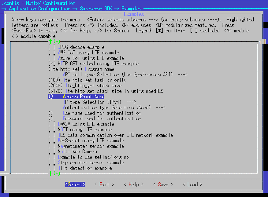
8.1.3. Operation check
Open a serial terminal and run the lte_http_get command.
-
Start the serial terminal.
Specify
/dev/ttyUSB0as the serial port,115200bps as the baudrate, and The following is an example of using the minicom terminal.minicom -D /dev/ttyUSB0 -b 115200 -
Run the
lte_http_getcommand from NuttShell.The usage of the lte_http_get command is shown below.
nsh> lte_http_get <url>
- url
-
Specifies the URL of a file located on the Internet. It should start with
http://orhttps://. If no url is specified, it will behttp://example.com/index.html.
This sample application will download the file specified in the url and output it to the serial terminal.
An example of executing the lte_http_get command is shown below.
nsh> lte_http_get
app_restart_cb called. reason:Modem restart by application.
pdn.session_id : 1
pdn.active     : 1
pdn.apn_type   : 0x202
pdn.ipaddr[0].addr : 10.212.60.255
app_localtime_report_cb called: localtime : "19/12/06 : 18:24:33"
set localtime completed: 2019/12/06,18:24:33
<!doctype html>
<html>
<head>
    <title>Example Domain</title>

    <meta charset="utf-8" />
    <meta http-equiv="Content-type" content="text/html; charset=utf-8" />
    <meta name="viewport" content="width=device-width, initial-scale=1" />
    <style type="text/css">
    body {
        background-color: #f0f0f2;
        margin: 0;
        padding: 0;
        font-family: -apple-system, system-ui, BlinkMacSystemFont, "Segoe UI", "Open Sans", "Helvetica Neue", Helvetica, Arial, sans-serif;

    }
    div {
        width: 600px;
        margin: 5em auto;
        padding: 2em;
        background-color: #fdfdff;
        border-radius: 0.5em;
        box-shadow: 2px 3px 7px 2px rgba(0,0,0,0.02);
    }
    a:link, a:visited {
        color: #38488f;
        text-decoration: none;
    }
    @media (max-width: 700px) {
        div {
            margin: 0 auto;
            width: auto;
        }
    }
    </style>
</head>

<body>
<div>
    <h1>Example Domain</h1>
    <p>This domain is for use in illustrative examples in documents. You may use this
    domain in literature without prior coordination or asking for permission.</p>
    <p><a href="https://www.iana.org/domains/example">More information...</a></p>
</div>
</body>
</html>
nsh>
|
If you specify a secured page starting with |
You can use the POST method of HTTP by changing wget to wget_post in this sample application.
Set the second argument of wget_post to the data to be POSTed, referring to the following example.
wget_post(url, "Hello spresense world!!" ,g_app_iobuffer, APP_IOBUFFER_LEN, app_wget_cb, NULL);Also, this sample application will output the downloaded file to the serial terminal, but it will not output the file to the +.
You can save it to a file by modifying some parts of the app_wget_cb() function as follow:
static void app_wget_cb(FAR char **buffer, int offset, int datend,
                        FAR int *buflen, FAR void *arg)
{
  int fd;

  fd = open("/mnt/spif/index.html", (O_WRONLY | O_APPEND));
  if ((fd < 0) && (errno == ENOENT))
    {
      fd = open("/mnt/spif/index.html", (O_CREAT | O_WRONLY), 0666);
    }
  /* Write HTTP data to local file */

  (void)write(fd, &((*buffer)[offset]), datend - offset);

  close(fd);
}|
The file will be saved in append mode, so if necessary, before you run the command |
8.2. LTE TLS Sample Applications
8.2.1. Overview
This sample program uses the LTE communication function to connect to a server using the TLS protocol and performs an HTTP POST.
8.2.1.1. Operating environment
-
Spresense Main Board
-
Spresense LTE extension board
-
SIM card
-
microSD card
For the connection method, refer to How to connect the Spresense main board to the Spresense LTE extension board for details.
In this sample application, a SIM card is required to connect to the network.
Please check the Confirmed LTE operator list.
8.2.2. Build procedure
This section shows the build procedure using the command line.
If you are using the IDE to build, please refer to the configuration information shown below.
-
Navigate to the
sdkdirectory. + . Load thebuild-env.shscript to enable the Tab completion feature of theconfig.pytool.cd spresense/sdk source tools/build-env.sh
-
Configure the SDK. + . Execute configuration with
examples/lte_tlsas argument.tools/config.py examples/lte_tlsChange the configuration of the sample application.
tools/config.py -m-
Set the APN parameters. (Set according to the SIM you are using.)
Application Configuration -> Spresense SDK -> Examples -> TLS data communication over LTE network example
- Access Point Name (CONFIG_EXAMPLES_LTE_TLS_APN_NAME)
- IP type Selection
- Authentication type Selection
- Username used for authentication (CONFIG_EXAMPLES_LTE_TLS_APN_USERNAME)
- Password used for authentication (CONFIG_EXAMPLES_LTE_TLS_PASSWD)

Configuration name Description Access Point Name
Access Point Name
IP type Selection
APN protocol. Select from
IPv4,IPv6, andIPv4/v6.Authentication type Selection
Authentication type. Select from
None,PAP, andCHAP.Username used for authentication
User name. If you select
Noneas the authentication type, the setting will be ignored.Password used for authentication
Password. If you select
Noneas the authentication type, the setting will be ignored. -
Configure the HTTPS settings.
It is possible to use the modem’s TLS protocol.
If you want to use it, see Use the modem’s TLS protocol.Application Configuration -> Spresense SDK -> Examples -> TLS data communication over LTE network example -> Directory for server certification files (CONFIG_EXAMPLES_LTE_TLS_CERTS_PATH)

Specifies the directory to store the root certificate of the server used for HTTPS. + . The default setting is /mnt/sd0/CERTS.
You can change the directory path to SPI-Flash by changing it to
/mnt/spif/CERTS.
-
-
Build the SDK.
Run
makecommand to build the SDK.makeIf the build succeed, the
nuttx.spkfile will be created directly under thesdkfolder. -
Write
nuttx.spkto the Spresense board.In this example, we set
/dev/ttyUSB0as the serial port and500000bps as the baudrate for write speed. You can change the settings according to your environment.tools/flash.sh -c /dev/ttyUSB0 -b 500000 nuttx.spk
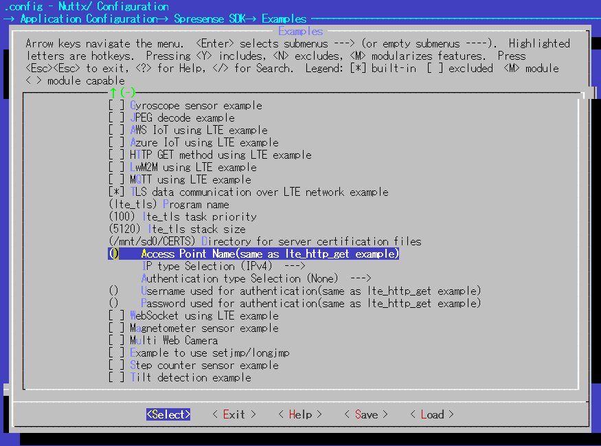
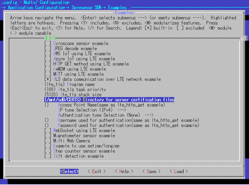
8.2.3. Operation check
Open a serial terminal and run the lte_tls command.
-
Start the serial terminal.
This is an example of using the minicom terminal with
/dev/ttyUSB0as the serial port and115200bps as the baudrate.minicom -D /dev/ttyUSB0 -b 115200 -
Run the
lte_tlscommand from NuttShell.The usage of the
lte_tlscommand is shown below.nsh> lte_tls <url>
- url
-
Specifies the URL of a file located on the Internet. It must start with
https://. If no url is specified, it will behttps://example.com/post.The root certificate of the server must be stored in the directory described in the configuration in advance.
This sample application uses the POST method of HTTP to send arbitrary data to the specified url.
An example of executing the lte_tls command is shown below. If the data is successfully sent, "HTTP status code = 200" will be output.
nsh> lte_tls https://httpbin.org/post
app_restart_cb called. reason:Modem restart by application.
app_radio_on_cb called. result: 0
app_activate_pdn_cb called. result: 0
pdn.session_id : 1
pdn.active     : 1
pdn.apn_type   : 0x202
pdn.ipaddr[0].addr : 10.212.60.255
app_localtime_report_cb called: localtime : "19/12/10 : 17:26:18"
set localtime completed: 2019/12/10,17:26:18
HTTP status code = 200
app_deactivate_pdn_cb called. result: 0
app_radio_off_cb called. result: 0
nsh>
In this sample application, the function create_http_post() is used to create the data to be POSTed.
static int create_http_post(const char    *host,
                            const char    *path,
                            char          *buffer,
                            size_t        buffer_size)
{
  const char *post_data = "Spresense!";
  const char http_post_request[] = "POST %s HTTP/1.1\r\n"
                                   "HOST: %s\r\n"
                                   "Connection: close\r\n"
                                   "Content-Length: %d\r\n"
                                   "\r\n"
                                   "%s";

  return snprintf(buffer, buffer_size,
                  http_post_request,
                  path,
                  host,
                  strlen(post_data),
                  post_data);
}
8.2.4. How to download a root certificate for HTTPS server access
8.2.4.1. Overview
To access a server using HTTPS or other secure communication via TLS, the root certificate must be downloaded and copied to a location specified by the application.
Spresense uses MbedTLS for secure communication by TLS and supports the following certificates
-
DER encoded binary X.509 (DER)
Binary certificate file in DER format. The extension is
.cer. -
Base 64 encoded X.509 (PEM)
ASCII text certificate file in Base 64 format. The extension is
.pem/.cer.
This section describes how to download a root certificate for server access.
8.2.4.2. How to download
Follow the steps below to download the file. The following procedure uses Windows/Chrome, but you can follow the same procedure for other OS and browsers to download the file by selecting the supported format.
-
Open the page of the site you wish to access. + . Open the page you wish to access in your browser. The following is an example of the page you want to access:
https://example.com/.
-
Open the site’s certificate.
-
Click the Security Communication button displayed in the page URL section.
-
Open the Security Protection menu.
-
Open a valid certificate.

-
-
Open the root certificate.
-
Open the certificate path (hierarchy).
-
Selects the Root certificate.
-
Click View Certificate.

-
-
Copy (export) the root certificate.
-
Select
Copy to File….
-
Navigate to the page where you select the format of the export file.

-
Select the format of the file to be exported.
Select
DER encoded binary X.509orBase 64 encoded X.509as supported by Spresense.
-
Select the export destination.

-
Execute the export.

-
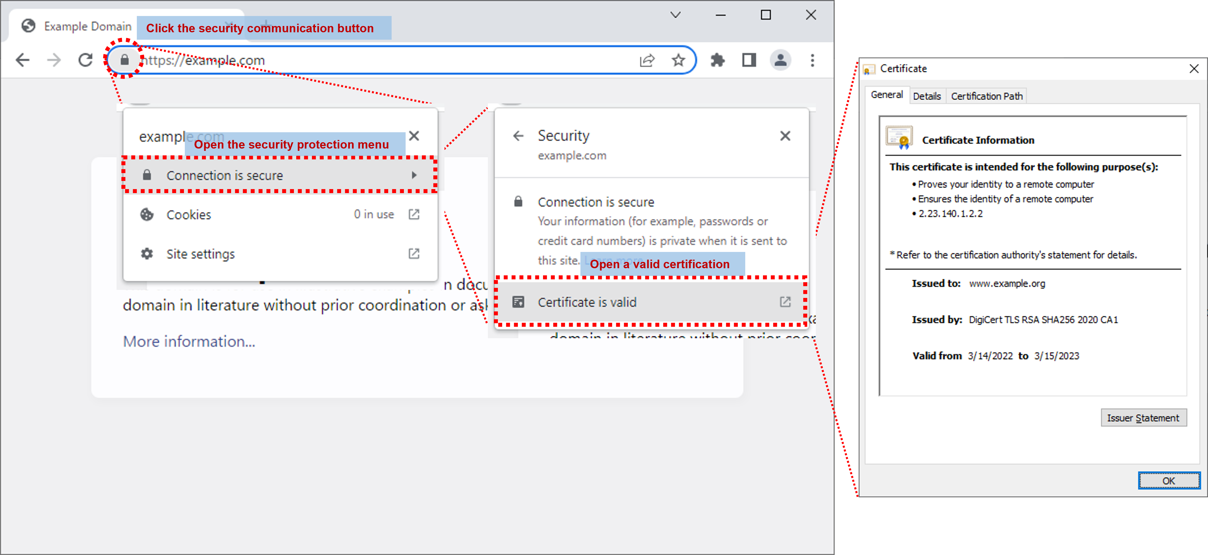
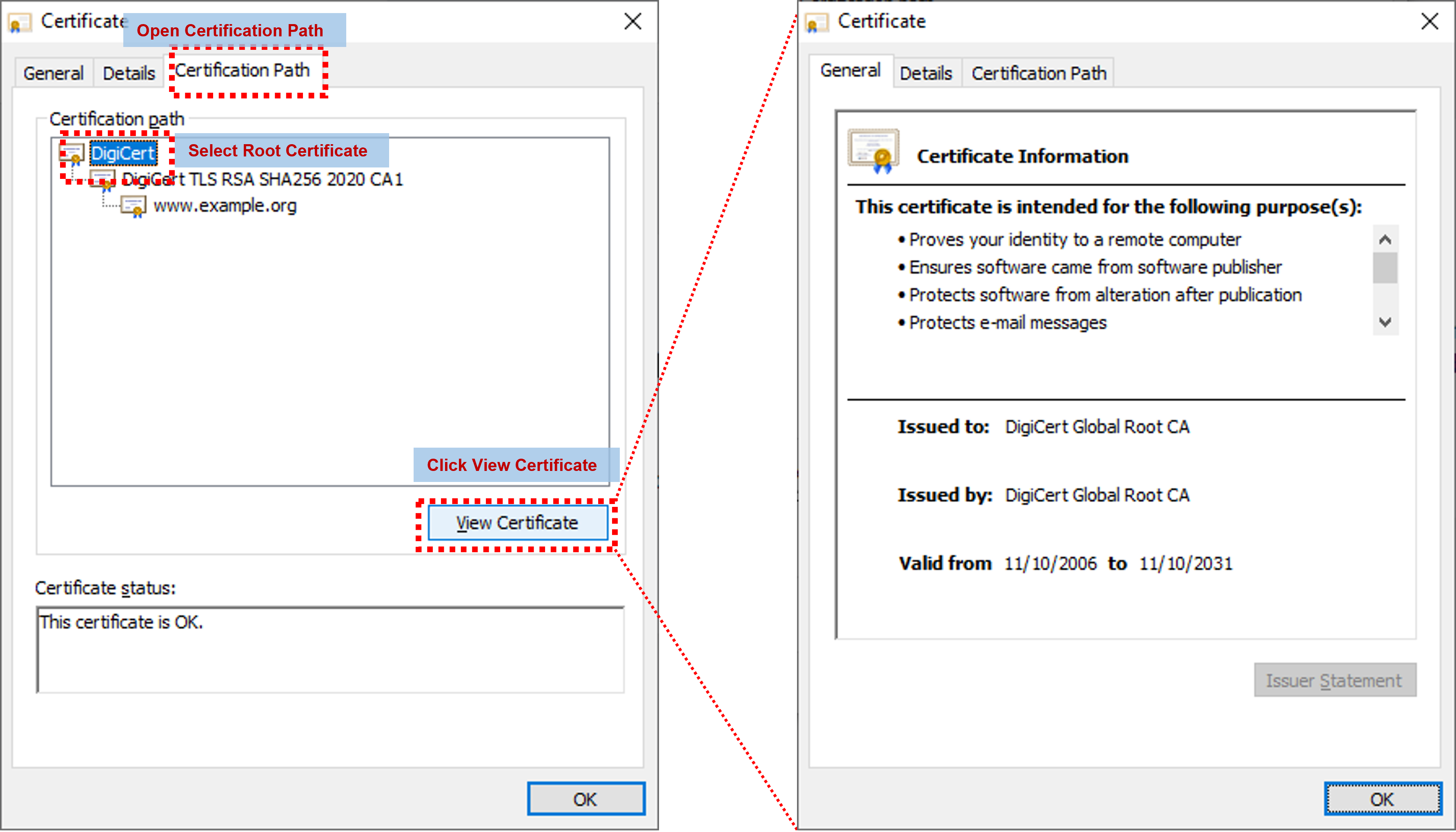
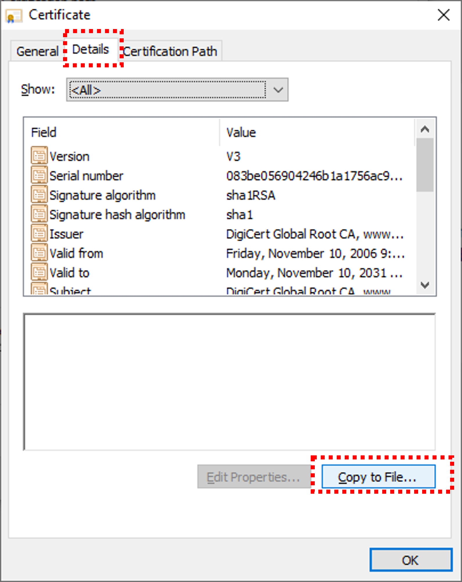
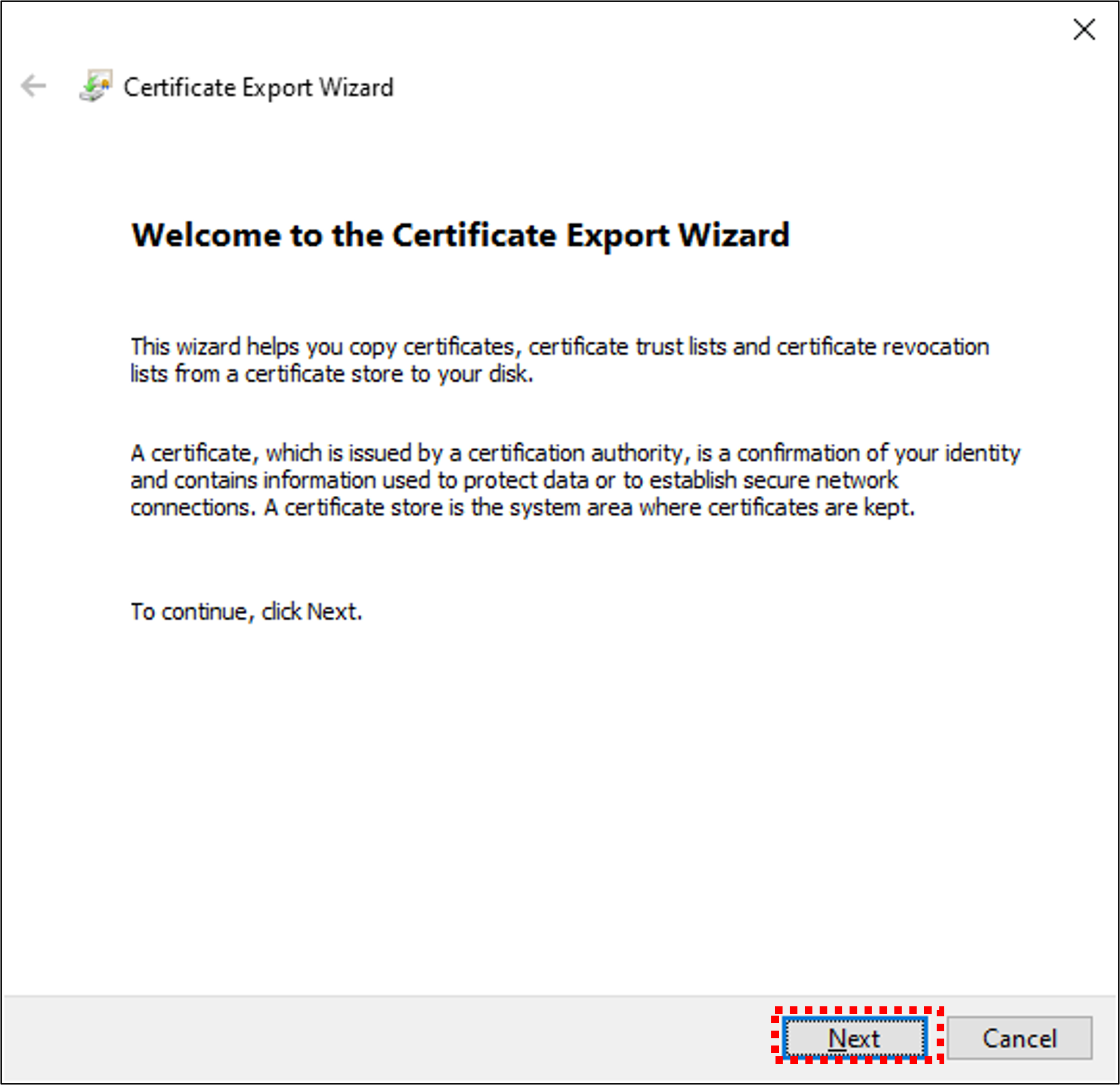
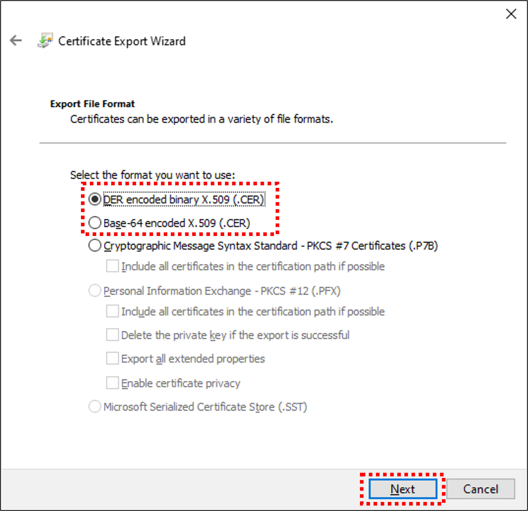
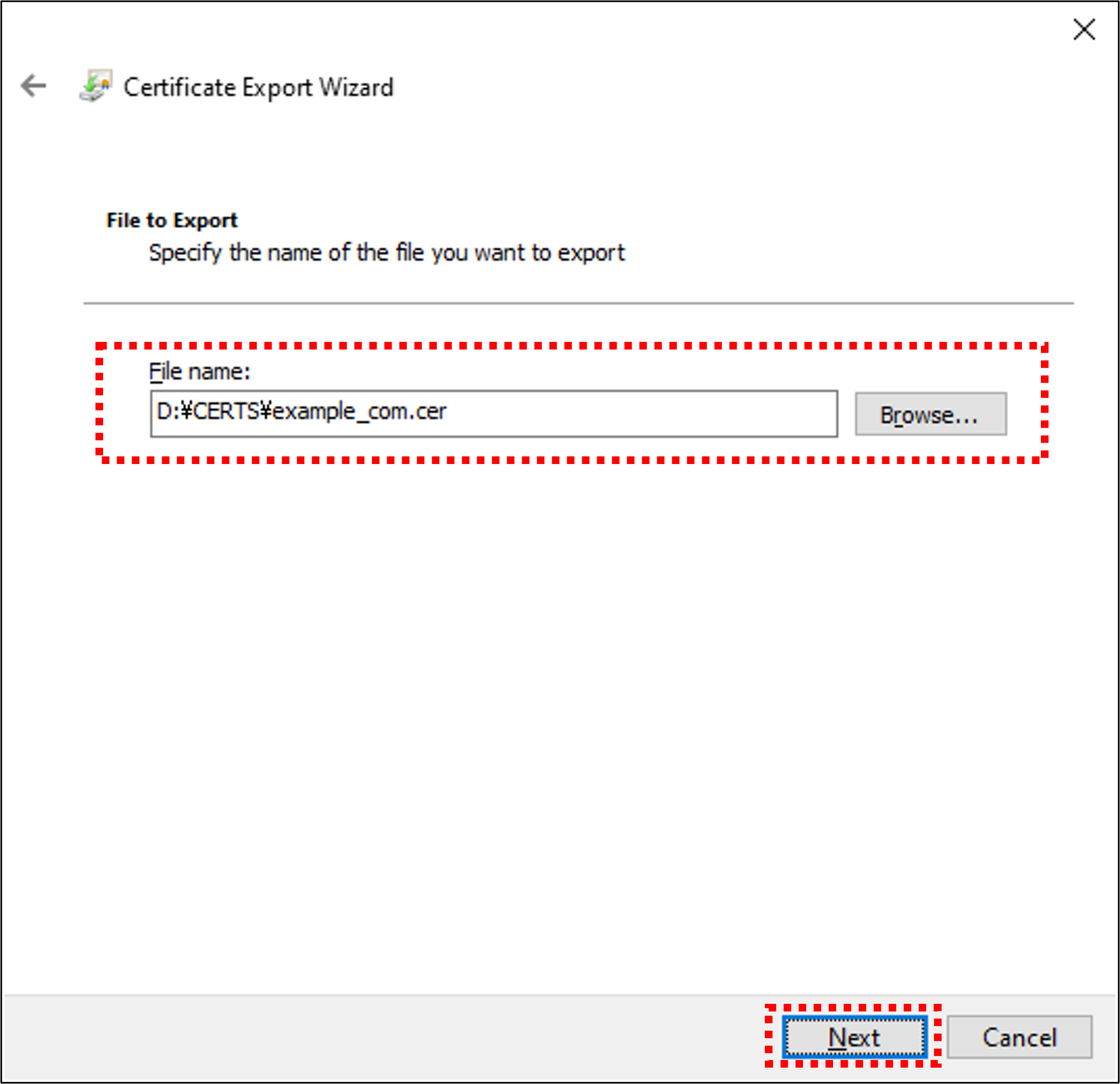
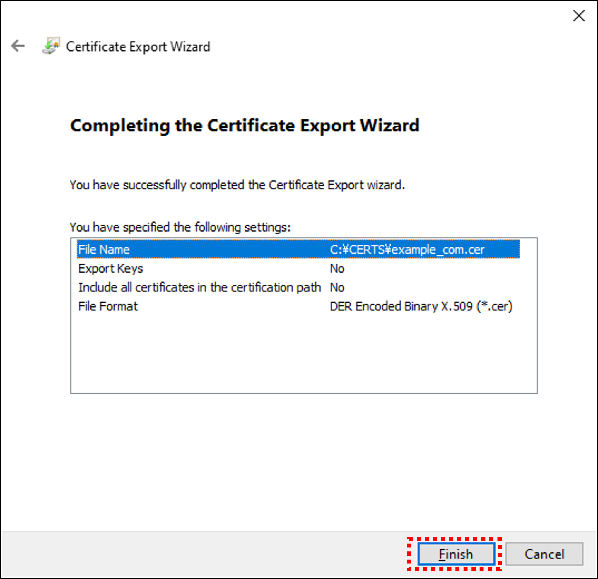
By performing the above steps, the root certificate is copied (exported). The copied root certificate can then be copied to the location specified in the application to enable secure communication with Spresense.
8.3. LTE MQTT Sample Application
8.3.1. Overview
This sample program connects to the MQTT broker using the LTE communication function, and publishes or subscribes to the specified topic name.
8.3.1.1. Operating environment
-
Spresense Main Board
-
Spresense LTE extension board
-
SIM card
For the connection method, please refer to How to connect the Spresense main board to the Spresense LTE extension board for details.
In this sample application, a SIM card is required to connect to the network. + link Please check the Confirmed LTE operator list.
8.3.2. Build procedure
This section shows the build procedure using the command line.
If you are using the IDE to build, please refer to the configuration information shown below.
-
Navigate to the
sdkdirectory.Loading the
build-env.shscript will enable the Tab completion feature of theconfig.pytool.cd spresense/sdk source tools/build-env.sh
-
Configure and build the SDK. + . Execute configuration with
examples/lte_mqttas argument.tools/config.py examples/lte_mqttChange the configuration of the sample application.
tools/config.py -m-
Set the APN parameters. (Set according to the SIM you are using.)
Application Configuration -> Spresense SDK -> Examples -> MQTT using LTE example
- Access Point Name (CONFIG_EXAMPLES_LTE_MQTT_APN_NAME)
- IP type (CONFIG_EXAMPLES_LTE_MQTT_APN_IPTYPE)
- Authentication type (CONFIG_EXAMPLES_LTE_MQTT_APN_AUTHTYPE)
- Username used for authentication (CONFIG_EXAMPLES_LTE_MQTT_APN_USERNAME)
- Password used for authentication (CONFIG_EXAMPLES_LTE_MQTT_APN_PASSWD)

Configuration name Description Access Point Name
Access Point Name
IP type
APN protocol, set to a value between 0 and 2. 0:
IPv4, 1:IPv62:IPv4/v6.Authentication type
Authentication type, set to a value between 0 and 2. Select from 0:
None, 1:PAP, 2:CHAP.Username used for authentication
User name. If you select
Noneas the authentication type, the setting will be ignored.Password used for authentication
Password. If you select
Noneas the authentication type, the setting will be ignored.If the build succeeds, the
nuttx.spkfile will be created directly under thesdkfolder.make
-
-
Write
nuttx.spkto the Spresense board.In this example, we set
/dev/ttyUSB0as the serial port and500000bps as the baudrate for write speed. You can change the settings according to your environment.tools/flash.sh -c /dev/ttyUSB0 -b 500000 nuttx.spk
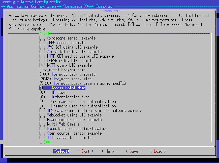
8.3.3. Operation check
Open a serial terminal and run the lte_mqtt command.
-
Start the serial terminal.
Here is an example of using a minicom terminal with a serial port of
/dev/ttyUSB0and a baudrate of115200bps. The following is an example of using the minicom terminal.minicom -D /dev/ttyUSB0 -b 115200 -
Run the
lte_mqttcommand from NuttShell.The usage of the lte_mqtt command is shown below.
nsh> lte_mqtt topicname <options>
- topicname
-
Name of the topic to publish or subscribe to
- options
Option Description --hostHostname of the MQTT broker. Default is
localhost.--portPort number to connect to. Default is
1883.。--qosQOS, a value between 0 and 2. Default is
2.--delimiterThe delimiter. The default is
\n.--clientidClient ID, defaults to
stdout_subscriber.--usernameUser name. Default is unset.
--passwordPassword. Default is unset.
--showtopicsWhether to show the topic name. Specify
onoroff. Default isoff.--cafile <file>Path to a file of trusted CA certificate.
--cert <file>Path to a file of client certificate.
--key <file>Path to a file of client private key.
--publish <message><message> to publish. If this option is not specified, then subscribe.
Spresense does not support
localhost. Be sure to specify the hostname with--host.
8.3.3.1. Publish a message from PC and subscribe to it with Spresense
This sample application connects to the MQTT broker and subscribes to the specified topic name.
After the subscribe is complete, it will display the published message on the serial port.
|
A separate operation is required to publish a message to the topic name. An example of the operation by using |
An example of executing the lte_mqtt command is shown below. If the subscription is completed successfully, "Subscribed 0" will be output.
To exit the subscribe process, press Ctrl-C on the terminal to exit the application and return to the NuttShell prompt.
nsh> lte_mqtt /test --host test.mosquitto.org
app_restart_cb called. reason:Modem restart by application.
app_radio_on_cb called. result: 0
app_activate_pdn_cb called. result: 0
pdn.session_id : 1
pdn.active     : 1
pdn.apn_type   : 0x202
pdn.ipaddr[0].addr : 10.212.60.255
app_localtime_report_cb called: localtime : "19/12/11 : 11:36:39"
set localtime completed: 2019/12/11,11:36:39
Connecting to test.mosquitto.org 1883
Connected 0
Subscribing to /test
Subscribed 0
Publish to the name of the topic you are subscribed to. + .
Here is an example of publishing on Ubuntu 16.04 by running the mosquitto_pub command.
-
Run the following command to install
mosquitto-clients.
sudo apt-get install mosquitto-clients
-
Execute the
mosquitto_pubcommand to publish the message.
mosquitto_pub -t /test -m "Hello Spresense world" -h test.mosquitto.org
-
If the publish succeeds, the following message will be output to the serial port.
Hello Spresense world
8.3.3.2. Publish a message from Spresense and subscribe to it with PC
This sample application connects to the MQTT broker and publishes to the specified topic name.
After the publish is complete, this application will exit.
|
A separate operation is required to subscribe to a message to the topic name. An example of the operation by using |
An example of executing the lte_mqtt command is shown below. If the publish is completed successfully, "Published 0" will be output.
nsh> lte_mqtt /test --host test.mosquitto.org --publish "Hello Spresense world"
app_restart_cb called. reason:Modem restart by application.
app_radio_on_cb called. result: 0
app_activate_pdn_cb called. result: 0
pdn.session_id : 1
pdn.active     : 1
pdn.apn_type   : 0x202
pdn.ipaddr[0].addr : 10.198.58.124
app_localtime_report_cb called: localtime : "22/03/30 : 22:10:55"
set localtime completed: 2022/03/30,22:10:55
Connecting to test.mosquitto.org 1883
Connected 0
Publishing to /test
Published 0
app_deactivate_pdn_cb called. result: 0
app_radio_off_cb called. result: 0
Here is an example of subscribing by running the mosquitto_sub command.
-
Execute the
mosquitto_subcommand to subscribe to the message.
mosquitto_sub -t /test -h test.mosquitto.org
-
If the subscribe succeeds, the following message will be output to your PC.
mosquitto_sub -t /test -h test.mosquitto.org
Hello Spresense world
8.3.3.3. For examples of SSL/TLS connections
The previous example used port 1883, but this section describes how to use port number 8883 using an SSL/TLS connection.
When executing the lte_mqtt command, the --cafile option allows you to specify the root certificate file path.
If you use test.mosquitto.org, download a file mosquitto.org.crt.
In advance, store this file in the location that can be accessed by Spresense. The following example shows how to transfer the file into Flash.
./tools/flash.sh -c /dev/ttyUSB0 -w mosquitto.org.crt
After a successful transfer, Spresense will be able to access this file under the path /mnt/spif/mosquitto.org.crt.
The procedure for running the lte_mqtt command is the same as before, except that the --port and --cafile options are added.
-
Example of MQTT publishing over SSL/TLS connection
nsh> lte_mqtt /test --host test.mosquitto.org --port 8883 --cafile /mnt/spif/mosquitto.org.crt --publish testmessage
-
Example of MQTT subscribe over SSL/TLS connection
nsh> lte_mqtt /test --host test.mosquitto.org --port 8883 --cafile /mnt/spif/mosquitto.org.crt
8.4. LTE LwM2M Sample Application
8.4.1. Overview
This sample program connects to an LwM2M server such as Leshan using LTE communication and Wakaama’s LwM2M Library to manage Spresense devices. Device location information acquired by the Spresense GNSS function can be retrieved via a server.
8.4.2. Operating environment
-
Device
-
Spresense main board
-
Spresense LTE extension board
-
SIM card
-
-
Service
8.4.3. Preparation
8.4.3.1. Device Connection
Please refer to the following for the connection method, please refer to How to connect the Spresense main board to the Spresense LTE extension board.
This sample application requires a SIM card to connect to the network.
Please check the Confirmed LTE operator list.
8.4.4. Build procedure
This section shows the build procedure using the command line.
If you are using the IDE to build, please refer to the following configuration information.
-
Navigate to the
sdkdirectory.Loading the
build-env.shscript will enable the Tab completion feature of theconfig.pytool.cd spresense/sdk source tools/build-env.sh
-
Configure the SDK.
Execute the configuration by specifying
examples/lte_lwm2mtools/config.py examples/lte_lwm2mChange the configuration of the sample application as needed.
tools/config.py -mSet the APN parameters. (Please set according to your SIM card.)
Application Configuration -> Spresense SDK -> Examples -> LwM2M using LTE example
- Access Point Name (CONFIG_EXAMPLES_LTE_LWM2M_APN_NAME)
- IP type (CONFIG_EXAMPLES_LTE_LWM2M_APN_IPTYPE)
- Authentication type (CONFIG_EXAMPLES_LTE_LWM2M_APN_AUTHTYPE)
- Username used for authentication (CONFIG_EXAMPLES_LTE_LWM2M_APN_USERNAME)
- Password used for authentication (CONFIG_EXAMPLES_LTE_LWM2M_APN_PASSWD)

Configurtion name Description Access Point Name
Access Point Name
IP type
APN Protocol. Set a value between 0 and 2.
0: IPv4,1: IPv6,2: IPv4/v6Authentication type
Authentication type. Set a value between 0 and 2.
0: None,1: PAP,2: CHAPUsername used for authentication
User name. If you select None as the authentication type, the setting will be ignored.
Password used for authentication
Password. If you select None as the authentication type, the setting will be ignored.
-
Build the SDK: Run
makecommand to build the SDK.makeIf the build is successful
nuttx.spkfile will be generated under thesdkdirectory folder. -
Write
nuttx.spkto the Spresense board.In this example, we set
/dev/ttyUSB0as the serial port and500000bps as the baudrate for write speed. You can change the settings according to your environment.tools/flash.sh -c /dev/ttyUSB0 -b 500000 nuttx.spk
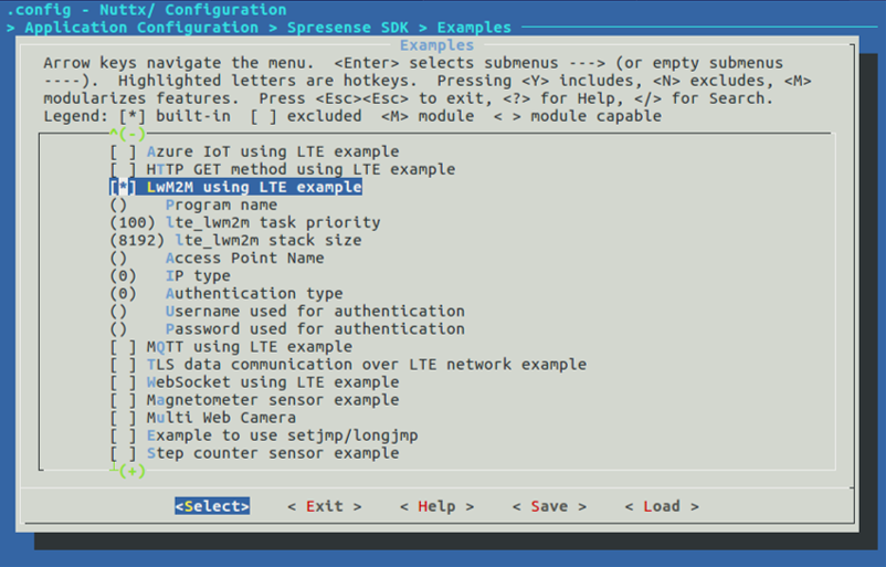
8.4.5. Operation check
Open a serial terminal and run the lte_lwm2m command.
-
Start the serial terminal.
Specify
/dev/ttyUSB0as the serial port,115200bps as the baudrate, and The following is an example of using the minicom terminal.minicom -D /dev/ttyUSB0 -b 115200 -
Run the
lte_lwm2mcommand from NuttShell.The usage of the
lte_lwm2mcommand is shown below.nsh> lte_lwm2m <options>
- options
Option Description -n <NAME>Specifies the name of the LwM2M endpoint.
-h <HOST>Specify the URL of the LwM2M server.
-p <PORT>Specifies the connection port to the LwM2M server.
-4Add to options for IPv4 connection to LwM2M server. (Default is IPv6 connection.)
-cIf this option is enabled, the dummy battery level is overwritten and updated over time.
An example of executing the
lte_lwm2mcommand is shown below.
8.4.5.1. Spresense terminal (Serial terminal)
Execute the lte_lwm2m command with any endpoint name (e.g. Spresense_LwM2M) as an argument.
nsh> lte_lwm2m -h leshan.eclipseprojects.io -p 5683 -4 -c -n Spresense_LwM2M
app_restart_cb called. reason:Modem restart by application.
app_radio_on_cb called. result: 0
app_activate_pdn_cb called. result: 0
pdn.session_id : 1
pdn.active     : 1
pdn.apn_type   : 0x202
pdn.ipaddr[0].addr : xxx.xxx.xxx.xxx
Trying to bind LWM2M Client to port 56830
LWM2M Client "Spresense_LwM2M" started on port 56830
> New Battery Level: 71
value changed!
app_localtime_report_cb called: localtime : "21/04/06 : 20:39:23"
set localtime completed: 2021/04/06,20:39:23
 -> State: STATE_REGISTERING
22 bytes received from [23.97.187.154]:5683
64 41 70 48  48 70 FB C6  82 72 64 0A  37 69 6D 77   dApHHp...rd.7imw
41 77 73 79  4C 36                                   AwsyL6
New Battery Level: 41
value changed!
 -> State: STATE_READY
 -> State: STATE_READY
8.4.5.2. Leshan LwM2M Server
Access Leshan LwM2M Server and select the endpoint name specified above from the Client Endpoint list.
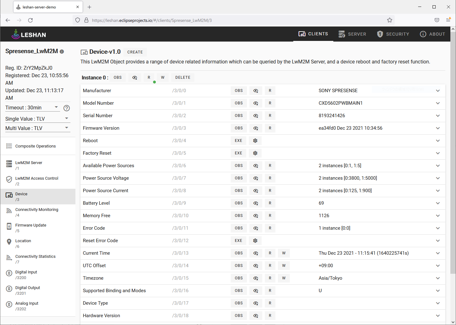
|
Depending on the operating environment, the communication state may become unstable and may not work properly. |
The objects implemented in this sample application are shown below.
-
Device Object
Device information can be read by Read operation from the server.
Table 1. Device Object Resource Description Manufacturer
"SONY SPRESENSE"
Model Number
"CXD5602PWBMAIN1"
Serial Number
Board-specific serial number (board unique ID)
Firmware Version
Firmware version (application version information)
Reboot
EXE operation will restart the board.
Battery Level
Random dummy value.
Memory Free
Heap free space (Kbyte)
Current Time
Current time
UTC Offset
"+09:00"
Timezone
"Asia/Japan"
Memory Total
Total memory capacity for application (1.5 MByte)
-
Firmware Update Object
You can send package files via
Packageand perform firmware updates viaUpdate.Table 2. Firmware Update Object Resource Description Package
Select a package file from File Input and send it to the device.
Update
EXE operation will perform a firmware update.
The file to be selected from
Packageis created using fwupdate/package.sh. When creating a package file containingnuttx.spk, run the following to create apackage.binfile.cd spresense/sdk ../examples/fwupdate/package.sh nuttx.spk
Press the
Packagebutton and select thepackage.binfile for theFile Inputto write. It will take about 15 minutes to write the file, depending on its size. If the timeout value of Leshan LwM2M Server is too small, the write will fail. Set the timeout to 30min before executing the write operation.
After writing is complete, run
Updateto perform a firmware update.The board will reboot after the firmware update is performed. If you still want to automatically connect to the Leshan server after the reboot, see How to start applications automatically.
-
Location Object
Device location information obtained from Spresense GNSS can be retrieved via server. When not in position, the latitude and longitude values are 0.0 and the
TimestampisJan 01 1970. These values are updated when positioning is available.Table 3. Location Object Resource Description Latitude
Latitude (ex) -43.5723
Longitude
Longitude (ex) 153.21760
Altitude
Altitude [m]
Radius
Radius [m]
Velocity
Velocity [3GPP-TS_23.032]
Timestamp
Positioning time
Speed
Movement speed [m/s]
-
Digital Input Object
The input values of the digital pins can be read by the Read operation from the server. See nuttx/arch/arm/include/cxd56xx/pin.h for pin numbers.
Press the CREATE button and create an instance by entering the pin number in the
Instance Idand any name in theApplication Type. In the example here, we specify the button switch (pin number = 89) that comes with the LTE expansion board. Since this is a pulled-up pin, setDigital Input Polarityto true.

GPIO values can be read by performing a Read operation after creating an instance. Pressing the button switch provided with the LTE expansion board sets the
Digital Input Stateto true and releasing it sets it to false.
Table 4. Digital Input Object Resource Description Digital Input State
Value read from GPIO
Digital Input Counter
Displays the number of interrupts when Edge Selection is used.
Digital Input Polarity
Polarity
Digital Input Edge Selection
Select the type of interrupt trigger
Digital Input Counter Reset
Clears the number of interruptions
Application Type
Any name
Timestamp
Time when GPIO is read
-
Digital Output Object
Any digital pin can be controlled by Write operation from the server. See nuttx/arch/arm/include/cxd56xx/pin.h for pin numbers.
As with Digital Input, press the CREATE button and create an instance by entering the pin number in the
Instance Idand any name in theApplication Type. The example here specifies LED0 (pin number = 97) on the main board.
By writing true/false to
Digital Output State, you can control whether the LED is on or off.
Table 5. Digital Output Object Resource Description Digital Output State
GPIO output set value
Digital Output Polarity
Polarity
Application Type
Any name
Timestamp
Time when GPIO is written
-
Analog Input Object
The value of any analog pin can be read out by the Read operation from the server. See How to use the A/D converter for SEN_AIN analog pin numbers on the LTE expansion board.
Press the CREATE button and create an instance by entering the SEN_AIN analog pin number in the
Instance Idand any name in theApplication Type. The example here specifies the SEN_AIN0 number on the LTE expansion board.
The
Analog Input Current Valuecan be read out as a normalized analog value in the range of 0.0~1.0.
Table 6. Analog Input Object Resource Description Analog Input Current Value
Analog value read from pin
Min Measured Value
Minimum analog value read out
Max Measured Value
Maximum analog value read out
Min Range Value
Minimum range(0.0)
Max Range Value
Maximum range(1.0)
Application Type
Any name
Reset Min and Max Measured Values
Clear minimum/maximum values
Timestamp
Time when Analog is read
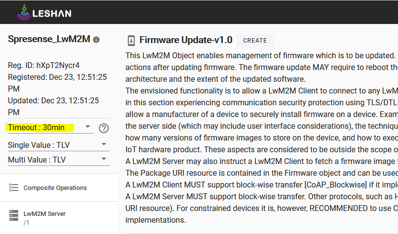
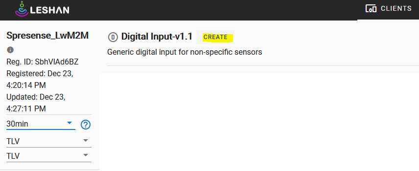
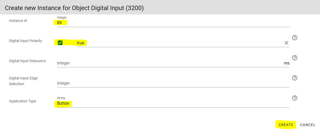
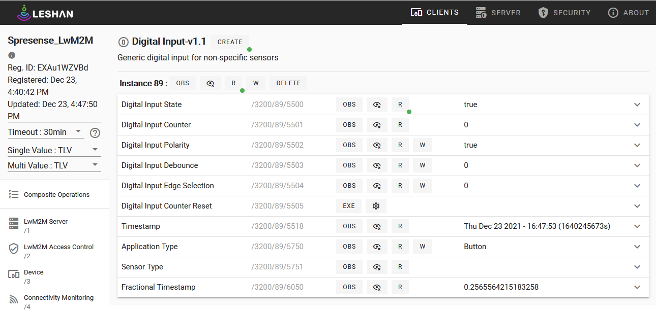
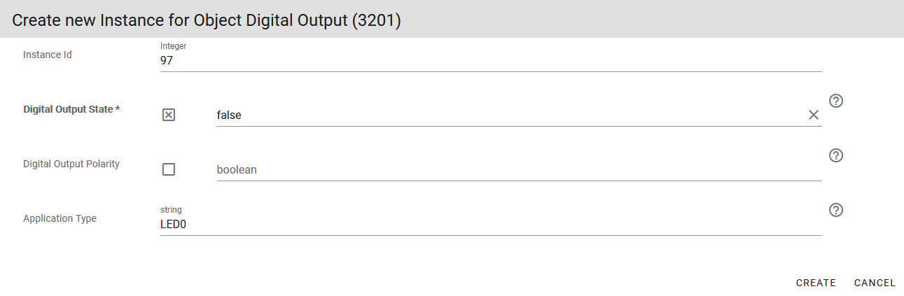
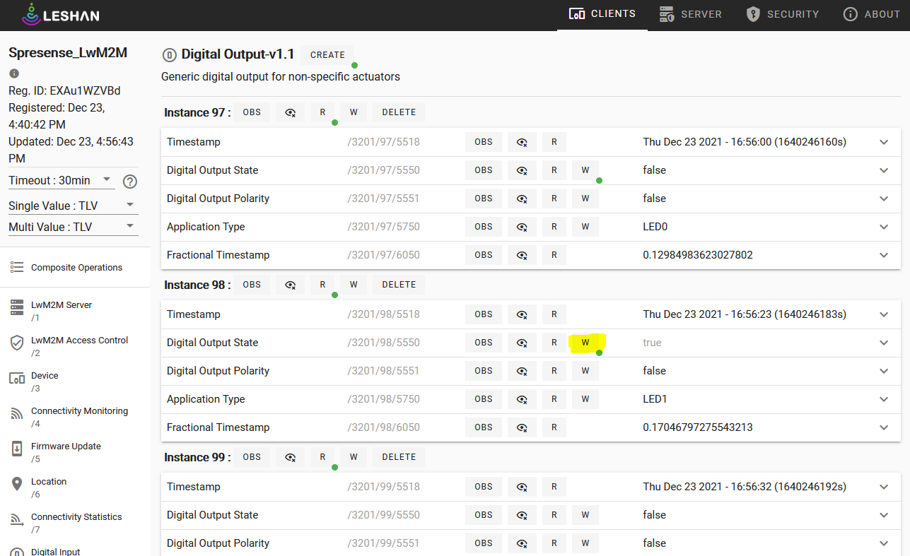
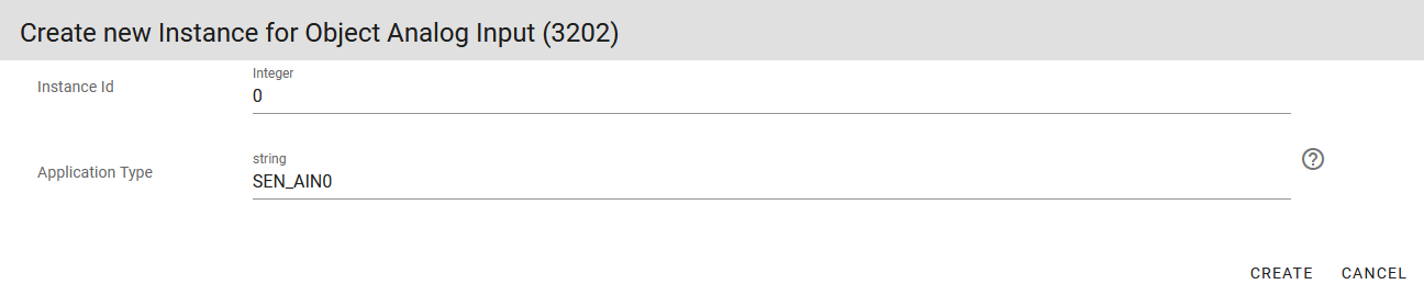
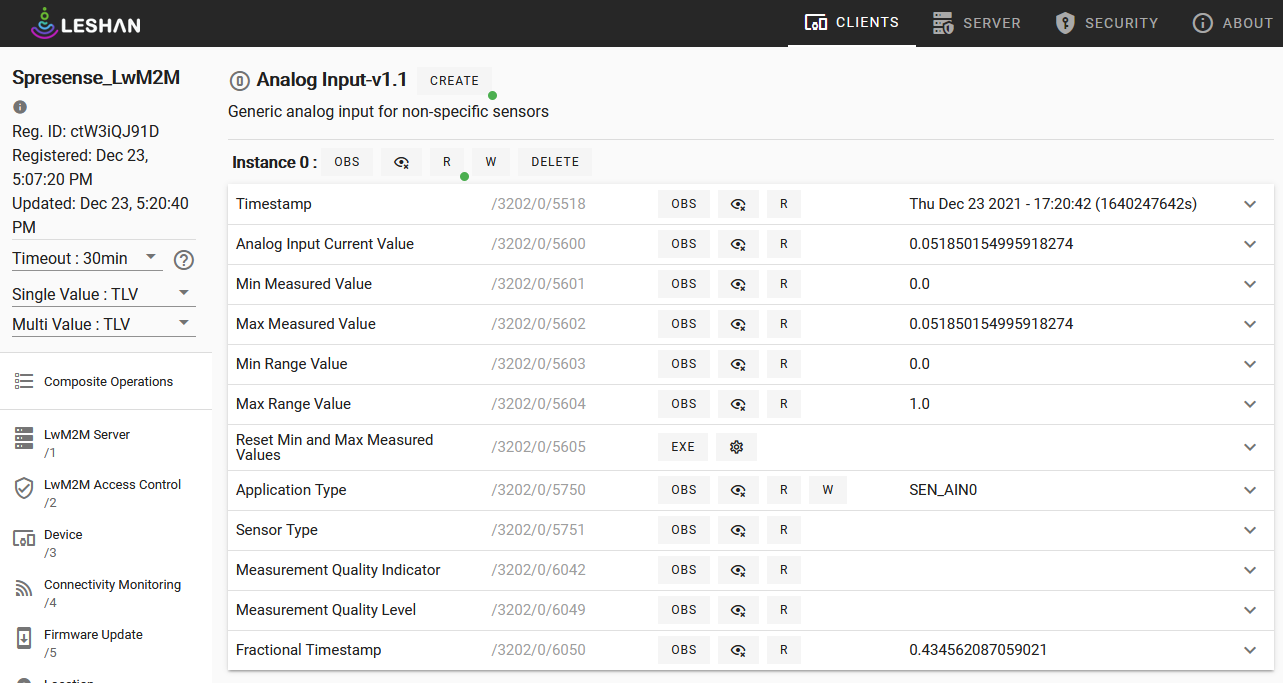
8.5. LTE AWS-IoT Sample Application
8.5.1. Overview
This sample program connects to the AWS-IoT server using the LTE communication function and AWS-IoT device SDK for embedded C, and performs MQTT communication.
8.5.2. Operating environment
-
Spresense main board
-
Spresense LTE extension board
-
SIM card
-
microSD card
-
AWS-IoT Core
Please refer to the following for the connection method, please refer to How to connect the Spresense main board to the Spresense LTE extension board.
This sample application requires a SIM card to connect to the network.
Please check the Confirmed LTE operator list.
In addition, in order to use AWS-IoT, you need to start using AWS-IoT and register your device with AWS-IoT as a thing.
For instructions on how to get started please refer to this link: Getting Started with AWS IoT.
The main points of operations required in AWS-IoT Core for confirming the operation of the sample are as follows.
For details, please refer to the descriptions of AWS-IoT Core.
-
Create and attach a thing
-
Issue certificates
-
Create and attach policy
-
Create and attach a thing
A thing represents a specific device or a logical entity.
You need to have the thing attached to the certificate. -
Issue ceritificates
Thing and policy must be attached to the certificates which the device uses.
For how to attach, see Attach a thing or policy to a client certificate.Please download the issued certificate for use on the device. There are three files to download.
-
Root certificate: AmazonRootCA1.pem
-
Client certificate: c3c4ff2375-certificate.pem.crt
-
Private key: c3c4ff2375-private.pem.key
When building or referencing, the above certifcates will be renamed and used.
In addition, the downloaded file will be stored in the microSD card under CERTS directory which will you create on your microSD card.
-
-
Create and attach policy
Policy detemines which AWS IoT resources a device can access.
You need to attach at least a policy to the certificates.
-
|
The certificate file names here are just for example. The file names may vary depending on your environment, so please change them accordingly. |
8.5.3. Build procedure
This section shows the build procedure using the command line.
If you are using the IDE to build, please refer to the following configuration information.
-
Navigate to the
sdkdirectory.Loading the
build-env.shscript will enable the Tab completion feature of theconfig.pytool.cd spresense/sdk source tools/build-env.sh
-
SDK configuration and build.
Execute the configuration by specifying
examples/lte_awsiot device/sdcardtools/config.py examples/lte_awsiot device/sdcardChange the configuration of the sample application.
tools/config.py -m-
Set the APN parameters. (Set according to the SIM you are using.)
Application Configuration -> Spresense SDK -> Examples -> AWS IoT using LTE example - Access Point Name (CONFIG_EXAMPLES_LTE_AWSIOT_APN_NAME) - IP type (CONFIG_EXAMPLES_LTE_AWSIOT_APN_IPTYPE) - Authentication type (CONFIG_EXAMPLES_LTE_AWSIOT_APN_AUTHTYPE) - Username used for authentication (CONFIG_EXAMPLES_LTE_AWSIOT_APN_USERNAME) - Password used for authentication (CONFIG_EXAMPLES_LTE_AWSIOT_APN_PASSWD)

Configuration name Description Access Point Name
Access Point Name
IP type
APN protocol, set to a value between 0 and 2. 0:
IPv4, 1:IPv62:IPv4/v6.Authentication type
Authentication type, set to a value between 0 and 2. Select from 0:
None, 1:PAP, 2:CHAP.Username used for authentication
User name. If you select
Nonefor the authentication type, the setting will be ignored.Password used for authentication
Password. If you select
Noneas the authentication type, the setting will be ignored. -
Set the parameters for using AWS-IoT. (Please set them according to your environment.)
Application Configuration -> Spresense SDK -> Examples -> AWS IoT using LTE example - AWS IoT cert folder (CONFIG_EXAMPLES_LTE_AWSIOT_CERT)
configuration name default value description AWS IoT cert folder
"/mnt/sd0/CERTS"
Set the location of the authentication file required to connect to AWS-IOT.
Application Configuration -> Spresense SDK -> Externals -> AWS IoT Device SDK for Embedded C -> AWS-IoT console - AWS_IOT_MQTT_HOST (CONFIG_EXTERNALS_AWSIOT_AWS_IOT_MQTT_HOST) - AWS_IOT_MQTT_PORT (CONFIG_EXTERNALS_AWSIOT_AWS_IOT_MQTT_PORT) - AWS_IOT_MQTT_CLIENT_ID (CONFIG_EXTERNALS_AWSIOT_AWS_IOT_MQTT_CLIENT_ID) - AWS_IOT_MY_THING_NAME (CONFIG_EXTERNALS_AWSIOT_AWS_IOT_MY_THING_NAME) - AWS_IOT_ROOT_CA_FILENAME (CONFIG_EXTERNALS_AWSIOT_AWS_IOT_ROOT_CA_FILENAME) - AWS_IOT_CERTIFICATE_FILENAME (CONFIG_EXTERNALS_AWSIOT_AWS_IOT_CERTIFICATE_FILENAME) - AWS_IOT_PRIVATE_KEY_FILENAME (CONFIG_EXTERNALS_AWSIOT_AWS_IOT_PRIVATE_KEY_FILENAME)

Configuration name Default value Description AWS_IOT_MQTT_HOST
MQTT broker name. Set the endpoint for your AWS-IoT environment.
AWS_IOT_MQTT_PORT
443
Port number of MQTT broker. AWS-IoT can connect with default value.。
AWS_IOT_MQTT_CLIENT_ID
"AWS-IoT-C-SDK"
MQTT client ID, which must be unique for each device.
AWS_IOT_MY_THING_NAME
"AWS-IoT-C-SDK"
Names of things.
AWS_IOT_ROOT_CA_FILENAME
"rootCA.crt"
File name of the root certificate, specifying the file downloaded from the AWS-IoT site.
AWS_IOT_CERTIFICATE_FILENAME
"cert.pem"
File name of the client certificate, specifying the file downloaded from the AWS-IoT site.
AWS_IOT_PRIVATE_KEY_FILENAME
"privkey.pem"
The file name of the private key to be used for client authentication; specify the file downloaded from the AWS-IoT site.
If the build is successful
sdkDirectly under the foldernuttx.spkfile will be generated.make
-
-
Write
nuttx.spkto the Spresense board.In this example, we set
/dev/ttyUSB0as the serial port and500000bps as the baudrate for write speed. You can change the settings according to your environment.tools/flash.sh -c /dev/ttyUSB0 -b 500000 nuttx.spk
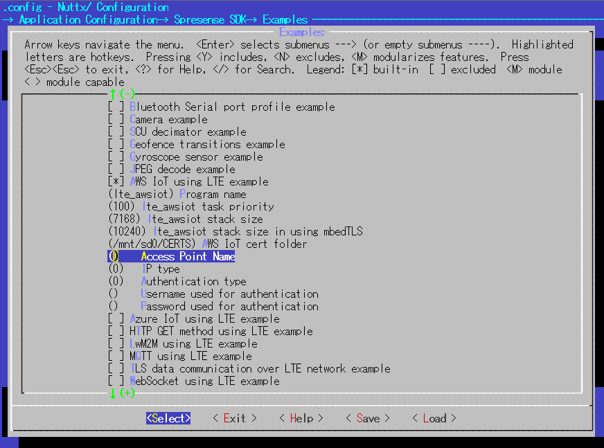
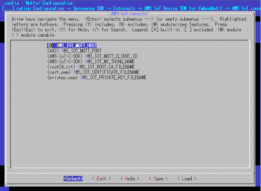
|
If you want to output debug information for AWS-IoT Core code, you can enable 'CONFIG_EXTERNALS_AWSIOT_ENABLE' from menuconfig. In that case, it is also necessary to increase the following STACKSIZE |
8.5.4. Operation check
Open a serial terminal and run the lte_awsiot command.
-
Start the serial terminal.
Specify
/dev/ttyUSB0as the serial port,115200bps as the baudrate, and here is an example of using the minicom terminal.minicom -D /dev/ttyUSB0 -b 115200 -
Run the
lte_awsiotcommand from NuttShell.The usage of the lte_awsiot command is shown below:
nsh> lte_awsiot <options>
- options
Option Description -xNumber of publish iterations. Default value is infinite.
This sample application connects to AWS-IoT via MQTT and subscribes to the "sdkTest/sub" topic. +This sample application connects to AWS-IoT via MQTT and subscribes to "sdkTest/sub" topic. After the subscribe is complete, publish it to the "sdkTest/sub" topic.
An example of executing the lte_awsiot command is shown below.
nsh> lte_awsiot -x 1 app_restart_cb called. reason:Modem restart by application. app_radio_on_cb called. result: 0 app_activate_pdn_cb called. result: 0 pdn.session_id : 1 pdn.active : 1 pdn.apn_type : 0x202 pdn.ipaddr[0].addr : 10.212.60.255 app_localtime_report_cb called: localtime : "19/12/13 : 14:15:16" set localtime completed: 2019/12/13,14:15:16 app_deactivate_pdn_cb called. result: 0 app_radio_off_cb called. result: 0
You can check the sent publish message on the AWS-IoT console.
|
Depending on the operating environment, the communication state may become unstable and may not work properly. |
8.6. LTE Azure-IoT Sample Application
8.6.1. Overview
This sample program connects to the Azure IoT Hub using the LTE communication function and NuttX’s WebClient to send and receive messages and files.
8.6.2. Operating environment
-
Device
-
Spresense main board
-
Spresense LTE extension board
-
SIM card
-
microSD card
-
-
Service
-
Azure IoT Hub
-
8.6.3. Preparation
8.6.3.1. Device Connection
Please refer to the following for the connection method, please refer to How to connect the Spresense main board to the Spresense LTE extension board.
This sample application requires a SIM card to connect to the network.
Please check the Confirmed LTE operator list.
8.6.3.2. Create a Azure IoT Hub/IoT device from Azure console
To use Azure IoT Hub, Azure IoT Hub and IoT devices must be created from Azure Portal.
For Azure IoT Hub and IoT devices, please refer to the Create an IoT hub using the Azure portal to create one.
8.6.3.3. Creating connection files
To connect to the Azure IoT Hub and send/receive data to/from Spresense, you will need an Azure IoT server certificate and an Azure IoT configuration file. The following is an explanation of how to obtain and save each of these files.
Azure IoT root CA file
In order to connect to the Azure IoT Hub server, the Azure IoT server certificate must be downloaded and stored on the SD card.
Copy the Baltimore CyberTrust Root certificate (file name portal-azure-com.pem) from the site Azure Portal https://portal.azure.com/ into the CERTS directory on the SD card.
SD card
└── CERTS
└── portal-azure-com.pemAs an example, we will explain how to download using the Firefox web browser.
|
See How to download a root certificate for HTTPS server access for instructions on how to download a root certificate using a browser other than Firefox. |
-
Access Azure Portal
https://portal.azure.com. -
Click the Authentication button on the left side of the Firefox browser address bar.

-
Click
More informationfromConnection secure

-
Click
View Certificate(V)fromSecurity
-
Click
PEM (cert)fromBaltimore CyberTrust Root`to download `portal-azure-com.pem
-
Create a
CERTSdirectory into the SD card root and copy the downloadedportal-azure-com.peminto it.
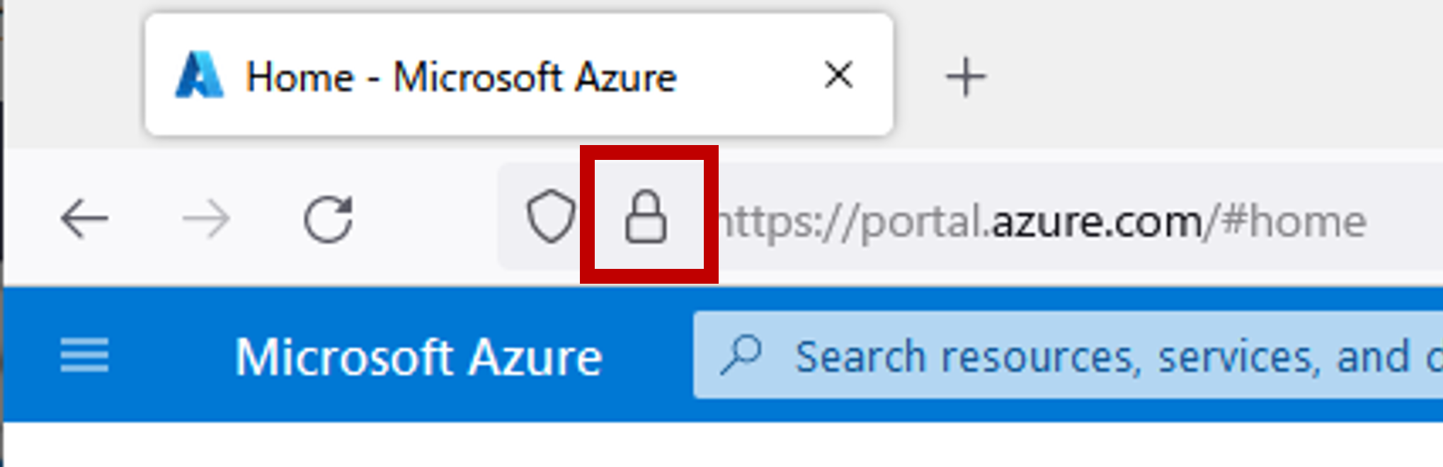

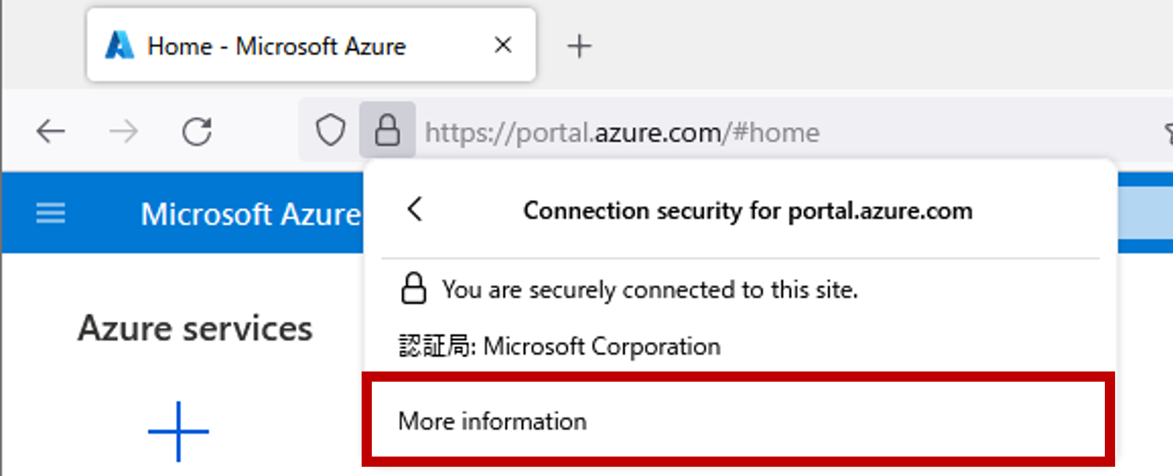
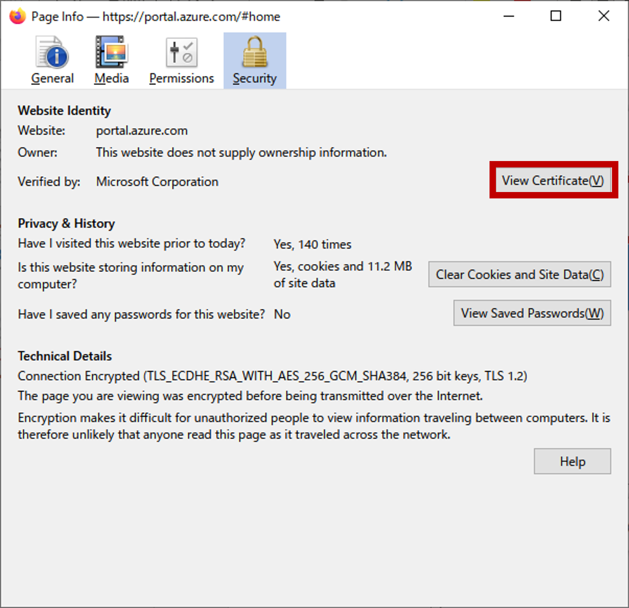
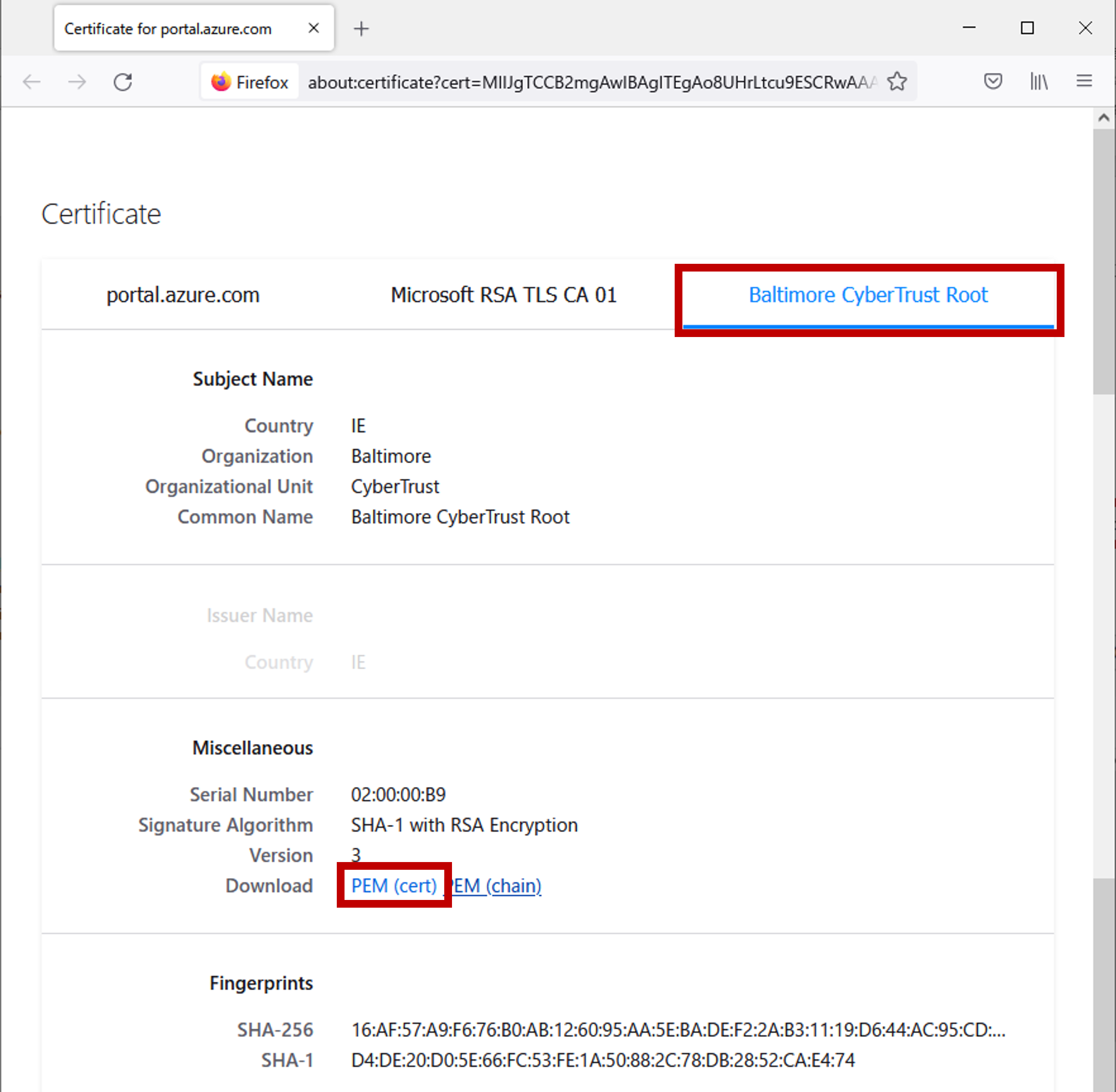
Azure IoT configuration file
To connect to Azure IoT Hub with the lte_azureiot sample, you need to copy a file containing the IoT Hub and IoT device names and the primary target shared access key information for the IoT device to the SD card.
Save the file as resources.txt with the Azure IoT Hub name <IoT Hub Name>, the IoT device id <Device ID> and the primary key <Primary Key> created in the Azure Portal in the following format.
<IoT Hub Name>
<Device ID>
<Primary Key>Then, create an azureiot directory on the SD card and copy resources.txt into it.
SD card
└── azureiot
└── resources.txt8.6.4. Build procedure
This section shows the build procedure using the command line.
If you are using the IDE to build, please refer to IDE configuration information.
-
Navigate to the
sdkdirectory.Loading the
build-env.shscript will enable the Tab completion feature of theconfig.pytool.cd spresense/sdk source tools/build-env.sh
-
Configure the SDK.
Execute the configuration by specifying
examples/lte_azureiottools/config.py examples/lte_azureiotChange the configuration of the sample application as needed.
tools/config.py -mSet the APN parameters. (Please set according to your SIM.)
Application Configuration -> Spresense SDK -> Examples -> Azure IoT using LTE example - Access Point Name (CONFIG_EXAMPLES_LTE_AZUREIOT_APN_NAME) - IP type Selection (CONFIG_EXAMPLES_LTE_AZUREIOT_APN_IPTYPE_*) - Authentication type Selection (CONFIG_EXAMPLES_LTE_AZUREIOT_APN_AUTHTYPE_*) - Username used for authentication (CONFIG_EXAMPLES_LTE_AZUREIOT_APN_USERNAME) - Password used for authentication (CONFIG_EXAMPLES_LTE_AZUREIOT_APN_PASSWD)

Configurtion name Description Access Point Name
Access Point Name
IP type Selection
APN Protocol. Set a value between 0 and 2.
0: IPv4,1: IPv6,2: IPv4/v6Authentication type Selection
Authentication type. Set a value between 0 and 2.
0: None,1: PAP,2: CHAPUsername used for authentication
User name. If you select None as the authentication type, the setting will be ignored.
Password used for authentication
Password. If you select None as the authentication type, the setting will be ignored.
-
Build the SDK: Run
makecommand to build the SDK.makeIf the build is successful
nuttx.spkfile will be generated under thesdkdirectory folder. -
Write
nuttx.spkto the Spresense board.In this example, we set
/dev/ttyUSB0as the serial port and500000bps as the baudrate for write speed. You can change the settings according to your environment.tools/flash.sh -c /dev/ttyUSB0 -b 500000 nuttx.spk
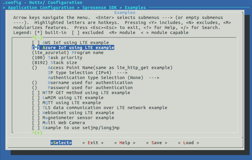
8.6.5. Operation check
Open a serial terminal and run the lte_azureiot command.
-
Start the serial terminal.
Specify
/dev/ttyUSB0as the serial port,115200bps as the baudrate, and the following is an example of using the minicom terminal.minicom -D /dev/ttyUSB0 -b 115200 -
Run the
lte_azureiotcommand from NuttShell.The usage of the
lte_azureiotcommand is shown below.nsh> lte_azureiot <options> <arg1> <arg2>
- options
Option Description sendSend a message to Azure IoT Hub. The message content is
<arg0>with a command such as"Hello!".recvReceive messages from Azure IoT.
uploadUpload a file to the Azure IoT Hub container. The file to upload is specified as
<arg1>and the file name on the container as<arg2>.downloadDownload a file from the Azure IoT Hub container. Specify the name of the file to download as
<arg1>and the location of the downloaded file as<arg2>.An example of executing the
lte_azureiotcommand is shown below.
8.6.5.1. Send a message
Run the az iot hub monitor-events command on Azure Cloud Shell to monitor.
8.6.5.2. Receive a message
Run the az iot device c2d-message send command on Azure Cloud Shell to send the message.
Azure Cloud Shell
azure_user@Azure:~ az iot device c2d-message send -d <Device ID> --data "spresense hello azure" -n <IoT Hub Name>
Spresense Terminal (Serial terminal)
nsh> lte_azureiot recv LTE connect... LTE connect...OK Successful Recv message: spresense hello azure LTE disconnect... lte_radio_off lte_power_off lte_finalize LTE disconnect...OK
|
Depending on the operating environment, the communication state may become unstable and may not work properly. |
8.7. LTE Websocket Sample Application(websocket_gmocoin)
8.7.1. Overview
This sample program uses the LTE communication function and Websocket library to obtain virtual currency transaction information provided by GMO Coin. Please refer to GMO Coin Public WebSocket API (external link) for GMO Coin’s API.
8.7.2. Operating environment
-
Spresense main board
-
Spresense LTE extension board
-
SIM card
-
microSD card
Please refer to the following for the connection method, please refer to How to connect the Spresense main board to the Spresense LTE extension board.
This sample application requires a SIM card to connect to the network.
Please check the Confirmed LTE operator list.
8.7.3. Build procedure
This section shows the build procedure using the command line.
If you are using the IDE to build, please refer to the following configuration information.
-
Navigate to the
sdkdirectory.Loading the
build-env.shscript will enable the Tab completion feature of theconfig.pytool.cd spresense/sdk source tools/build-env.sh
-
Configure the SDK.
Execute the configuration by specifying
examples/lte_awsiot device/sdcardtools/config.py examples/lte_websocket_gmocoin -
Build the SDK. Run
makecommand to build the SDK.makeIf the build is successful
sdkDirectly under the foldernuttx.spkfile will be generated. -
Write
nuttx.spkto the Spresense board.In this example, we set
/dev/ttyUSB0as the serial port and500000bps as the baudrate for write speed. You can change the settings according to your environment.tools/flash.sh -c /dev/ttyUSB0 -b 500000 nuttx.spk
8.7.4. Copy Root certificate
The server root certificate for GMO Coin’s API is required to run this sample program. Please follow the instructions below to download the certificate and copy it to the certain location.
-
Go to
https://api.coin.z.com/and download the root certificate.Download the root certificate for
https://api.coin.z.com/with reference to How to download a root certificate for HTTPS server access. -
Rename the downloaded root certificate to
rootcacert_r3.cerand copy it to the top directory of the SD card. -
Insert the copied SD card into the LTE expansion board.
8.7.5. Operation check
Open a serial terminal and run the lte_awsiot command.
-
Start the serial terminal.
Specify
/dev/ttyUSB0as the serial port,115200bps as the baudrate, and here is an example of using the minicom terminal.minicom -D /dev/ttyUSB0 -b 115200 -
Run the
lte_sysctlcommand from NuttShell to start LTE daemon.The following example assumes that the APN name is
internet, the authentication method isCHAP, the user name isuser, and the password ispass.nsh> lte_sysctl -a internet -v 2 -u user -p pass start
-
Run the
ifupcommand from NuttShell to connect to LTE network.nsh> ifup eth0 ifup eth0...OK
-
Run the
websocket_gmocoincommand from NuttShell.The usage of the websocket_gmocoin command is shown below.
nsh> websocket_gmocoin <command> <symbol>
- command
-
Choose to subscribe or unsubscribe.
-
subscribe
-
unsubscribe
-
- symbol
-
Select the type of transaction information to subscribe (or unsubscribe). The available
symbolare as followsBTC : Bitcoin ETH : Ethereum BCH : Bitcoin Cash LTC : Litecoin XRP : Ripple XEM : New Economy Movement XLM : Stellar BTC_JPY : Bitcoin - Yen ETH_JPY : Ethereum - Yen BCH_JPY : Bitcoin Cash - Yen LTC_JPY : Litecoin - Yen XRP_JPY : Ripple - Yen
An example of running the websocket_gmocoin command is shown below. If the command is successfully executed, the transaction information will be output in Json format at the timing when the transaction information is updated.
nsh> websocket_gmocoin subscribe BTC
nsh> wss main task started.
{"channel":"ticker","ask":"5365700","bid":"5365300","high":"5452200","last":"5365500","low":"5288150","symbol":"BTC","timestamp":"2022-04-07T05:20:17.468Z","volume":"257.2177"}
{"channel":"ticker","ask":"5365950","bid":"5365300","high":"5452200","last":"5365900","low":"5288150","symbol":"BTC","timestamp":"2022-04-07T05:21:39.003Z","volume":"257.1498"}
{"channel":"ticker","ask":"5365950","bid":"5365300","high":"5452200","last":"5365950","low":"5288150","symbol":"BTC","timestamp":"2022-04-07T05:21:39.003Z","volume":"257.1498"}
{"channel":"ticker","ask":"5366150","bid":"5365300","high":"5452200","last":"5366150","low":"5288150","symbol":"BTC","timestamp":"2022-04-07T05:21:59.119Z","volume":"257.2198"}
{"channel":"ticker","ask":"5366200","bid":"5365300","high":"5452200","last":"5366200","low":"5288150","symbol":"BTC","timestamp":"2022-04-07T05:22:24.583Z","volume":"257.2297"}
8.8. SMS Sample Application
8.8.1. Overview
This sample program is a sample for sending and receiving SMS (Short Message Service).
8.8.2. Operating environment
-
Device
-
Spresense main board
-
Spresense LTE extension board
-
SIM card
-
Please refer to the following for the connection method, please refer to How to connect the Spresense main board to the Spresense LTE extension board.
In addition, an SMS-enabled SIM card must be prepared in order to use SMS. Please refer to Confirmed LTE operator list and prepare a SIM card with a plan that supports SMS.
|
If the LTE firmware version is RK_03_00_00_00_00_04121_001, the SMS function may not work. (Please refer to here ) |
8.8.3. Build procedure
This section shows the build procedure using the command line.
If you are using the IDE to build, please refer to the following configuration information.
-
Navigate to the
sdkdirectory.Loading the
build-env.shscript will enable the Tab completion feature of theconfig.pytool.cd spresense/sdk source tools/build-env.sh
-
Configure the SDK.
Execute the configuration by specifying
examples/sms_sendandexamples/sms_recvtools/config.py examples/sms_send examples/sms_recv -
Build the SDK. Run
makecommand to build the SDK.makeIf the build is successful
nuttx.spkfile will be generated under thesdkdirectory folder. -
Write
nuttx.spkto the Spresense board.In this example, we set
/dev/ttyUSB0as the serial port and500000bps as the baudrate for write speed. You can change the settings according to your environment.tools/flash.sh -c /dev/ttyUSB0 -b 500000 nuttx.spk
8.8.4. Operation check
Open a serial terminal and run the sms_recv and sms_send command.
-
Start the serial terminal.
Specify
/dev/ttyUSB0as the serial port,115200bps as the baudrate, and The following is an example of using the minicom terminal.minicom -D /dev/ttyUSB0 -b 115200 -
Run the
lte_sysctlandifupcommand from NuttShell to connect to LTE network.See Use the LTE network daemon to make network connections. for details on the
lte_sysctlandifupcommands.nsh> lte_sysctl <options> start nsh> nsh> ifup eth0 ifup eth0...OK
-
Run the
sms_recvcommand from NuttShell and wait for incoming SMS message.nsh> sms_recv &
Commands can be run in the background by appending
&to the end of the command.The
sms_recvcommand wait for incoming SMS and outputs the incoming message to NuttShell when an SMS is received. -
Run the
sms_sendcommand from NuttShell to send a SMS message.The usage of the sms_send command is shown below.
nsh> sms_send <phone number> <text message> [<enable status report>]
- <phone number>
-
Destination Phone Number
- <text message>
-
Message body
- <enable status report>
-
Flag whether or not to receive SMS receipt confirmation notification. This parameter is optional.
Value Description 0Do not receive SMS receipt confirmation notification
1Receive SMS receipt confirmation notification
An example of executing the sms_send and sms_recv commands is shown below.
nsh> sms_recv & sms_recv [14:100] nsh> socket open success:3 nsh> nsh> sms_send 080xxxxxxxx "Hello Spresense" 1 socket open success:3 Successfully sent SMS to 080xxxxxxxx Get reference id[0] = 241
When an SMS is received by the terminal, it will be output to NuttShell as follows
nsh> ----------------------------------------------- sent time : 21/12/17 : 13:48:52 +09 message type : Deliver message source address length: 22 message body length : 10 source address : 080xxxxxxxx message body : Hello Spresense
If you run the sms_send command with 1 in the <enable status report> parameter, NuttShell will output the following message when the sent SMS reaches its destination.
sent time : 21/12/17 : 13:48:52 +09 message type : Status report message source address length: 0 message body length : 10 reference ID : 241 status : success discharge time : 21/12/17 : 13:48:57 +09
The table below details each parameter that is displayed when receiving an SMS.
| Parameter | Description |
|---|---|
|
Indicates the time the SMS was sent to the provider’s server. |
|
Indicates the type of message received. |
|
Represents the number of bytes of the source telephone number encoded in the UCS2 character set. |
|
Indicates the number of bytes in the body text encoded in the UCS2 character set. |
|
The source phone number. |
|
The body of the received SMS. |
|
This is an ID that refers to which acknowledgement of the sent SMS was received or not. By referring to this value and the value of |
|
Indicates the arrival result of the sent SMS. If the SMS reached its destination, |
|
Indicates the time the sent SMS reached its destination. |
8.9. Use the LTE network daemon to make network connections.
This section describes the commands(lte_sysctl) to connect to the network using the LTE network daemon.
Once the network connection is successfully established, data communication will be possible using commands such as wget.
From Spresense SDK v2.3.0, the command name has been changed from lte_daemon to lte_sysctl. If you are using v2.2.0 or earlier SDK, please replace lte_sysctl with lte_daemon in the following explanation.
|
8.9.1. About the lte_sysctl command
The lte_sysctl is a command on the NuttShell command line to control LTE power and communication.
nsh> lte_sysctl <options> <action>
This command enables network communication with commands for communication such as wget and nslookup.
This command has subcommands called action, each with the following functions.
- Subcommand (
<action>) -
[options="header, autowidth"].
action |
explanation |
|
Start LTE’s network daemon. |
|
Stop LTE’s network daemon. |
|
Displays the configured access point information, communication method, and firmware version of the LTE module. |
|
Reset LTE module settings to factory defaults. (*Additional configuration is required) |
The start subcommand also has the following options.
-
startsubcommand options (<options>) -
[options="header, autowidth"].
Options |
Description |
|
Access Point Name (APN). |
|
APN type, set to a hexadecimal value. See lte_apn_setting.ip_type for detailed values. |
|
APN protocol, set to a value between 0 and 2. (0: |
|
Authentication type, set to a value between 0 and 2. (0: |
|
APN user name. If 0: |
|
Password for APN. If you select 0: |
|
LTE communication method. Select |
8.9.2. Build procedure
This section shows the command line build procedure.
When building using the IDE, please refer to the configuration information shown below.
-
Navigate to the
sdkdirectory.Load the
build-env.shscript to enable the Tab completion feature of theconfig.pytool.cd spresense/sdk source tools/build-env.sh
-
Configure the SDK.
Execute configuration with
feature/lteas argument.tools/config.py feature/lteThe default value for each option can be changed. (except for APN type). For details, please refer to Procedure to change the APN setting from the default setting.
Please refer to Instructions for enabling the factoryreset subcommand to update the configuration to enable the
factoryresetsubcommand. -
Execute
makecommand for building the SDK.makeIf the build succeeds, the
nuttx.spkfile will be created directly under thesdkfolder. -
Write
nuttx.spkto the Spresense board.In this example, we set
/dev/ttyUSB0as the serial port and500000bps as the baudrate for write speed. You can change the settings according to your environment.tools/flash.sh -c /dev/ttyUSB0 -b 500000 nuttx.spkIn the configuration of examples using LTE (e.g. examples/lte_http_get)
CONFIG_LTE_SYSCTLis enabled, so you can use it as is.
8.9.3. Operation check
8.9.3.1. To start an LTE connection using the start subcommand
-
Run
lte_sysctlfrom NuttShell with thestartsubcommand to start the LTE daemon.The following command is an example where the APN name is
internet, the authentication method isCHAP, the user name isuser, and the password ispass.nsh> lte_sysctl -a internet -v 2 -u user -p pass start
-
Run the
ifup eth0command from NuttShell to enable the LTE network interface.You can see that the network address has been assigned by running the
ifconfigcommand as followsnsh> ifup eth0 ifup eth0...OK nsh> nsh> ifconfig eth0 Link encap:Ethernet HWaddr 00:00:00:00:00:00 at UP inet addr:100.92.28.11 DRaddr:0.0.0.0 Mask:0.0.0.0 inet6 addr: ::/0 inet6 DRaddr: ::/0 -
With a network connection, run the
wgetcommand from NuttShell to download a file by specifying the URL of a file located on the Internet.nsh> ifconfig eth0 Link encap:Ethernet HWaddr 00:00:00:00:00:00 at UP inet addr:100.92.28.11 DRaddr:0.0.0.0 Mask:0.0.0.0 inet6 addr: ::/0 inet6 DRaddr: ::/0 nsh> nsh> wget -o /mnt/spif/index.html http://www.example.com/index.html nsh> nsh> nsh> cat /mnt/spif/index.html <!doctype html> <html> <head> <title>Example Domain</title> <meta charset="utf-8" /> <meta http-equiv="Content-type" content="text/html; charset=utf-8" /> <meta name="viewport" content="width=device-width, initial-scale=1" /> <style type="text/css"> body { background-color: #f0f0f2; margin: 0; padding: 0; font-family: -apple-system, system-ui, BlinkMacSystemFont, "Segoe UI", "Open Sans", "Helvetica Neue", Helvetica, Arial, sans-serif; } div { width: 600px; margin: 5em auto; padding: 2em; background-color: #fdfdff; border-radius: 0.5em; box-shadow: 2px 3px 7px 2px rgba(0,0,0,0.02); } a:link, a:visited { color: #38488f; text-decoration: none; } @media (max-width: 700px) { div { margin: 0 auto; width: auto; } } </style> </head> <body> <div> <h1>Example Domain</h1> <p>This domain is for use in illustrative examples in documents. You may use this domain in literature without prior coordination or asking for permission.</p> <p><a href="https://www.iana.org/domains/example">More information...</a></p> </div> </body> </html> nsh> nsh>
8.9.3.2. To check the connection status using the stat subcommand
-
Run
lte_sysctlfrom NuttShell with thestatsubcommand to check the LTE connection status.nsh> lte_sysctl stat Daemon state : running APN Name: internet IP type: IPv4 Authentication: CHAP Username: user Password: pass RAT: CAT-M1 VER: RK_02_01_02_10_108_54
The above example shows that the daemon is
running, the APN name isinternet, the APN IP type isIPv4, the authentication type isCHAP, the user name isuser, the password ispass, the communication method isCAT-M1and the LTE module firmware version isRK_02_01_02_10_108_54.
8.9.3.3. To terminate the LTE connection using the stop subcommand
-
Run the
ifdown eth0command from NuttShell to disable the LTE network interface.The
ifconfigcommand as shown below shows that the network address assignment has been removed.nsh> ifdown eth0 ifdown eth0...OK nsh> nsh> ifconfig eth0 Link encap:Ethernet HWaddr 00:00:00:00:00:00 at DOWN inet addr:0.0.0.0 DRaddr:0.0.0.0 Mask:0.0.0.0 inet6 addr: ::/0 inet6 DRaddr: ::/0
-
Run
lte_sysctlfrom NuttShell with thestopsubcommand to terminate the LTE daemon.nsh> lte_sysctl stop nsh>
8.9.3.4. To restore the LTE module configuration values to factory defaults using the factoryreset subcommand
-
Run the
lte_sysctl factoryresetcommand from NuttShell.nsh> lte_sysctl factoryreset Factory reset running... Please do not turn off the device. Factory reset takes around 30 sec. Factory reset done.
To enable the
factoryresetsubcommand, refer to Instructions for enabling the factoryreset subcommand and update the configuration.This command takes about 30 seconds to execute. Please do not turn off the power to Spresense while it is running.
This command is only available on boards whose LTE module firmware version starts with
RK_02_01_.
Other boards cannot be used.
8.9.4. Procedure to change the APN setting from the default setting
This section describes the procedure to change the default APN settings specified as the argument of lte_sysctl.
-
Modify the configuration of lte_sysctl.
tools/config.py -m-
Set the APN parameters. (Set according to the SIM you are using.)
Application Configuration -> Spresense SDK -> System tools -> lte_sysctl - Access Point Name (CONFIG_LTE_SYSCTL_APN_NAME) - IP type Selection - Authentication type Selection - Username used for authentication (CONFIG_LTE_SYSCTL_APN_USERNAME) - Password used for authentication (CONFIG_LTE_SYSCTL_APN_PASSWD)

Configuration name Default value Explanation Access Point Name
Access Point Name
IP type Selection
0:
IPv4APN protocol, set to a value between 0 and 2. 0:
IPv4, 1:IPv62:IPv4/v6.Authentication type Selection
0:
NoneAuthentication type, set to a value between 0 and 2. Select from 0:
None, 1:PAP, 2:CHAP.Username used for authentication
User name. If you select
Noneas the authentication type, the setting will be ignored.Password used for authentication
Password. If you select
Nonefor the authentication type, the setting will be ignored.
-
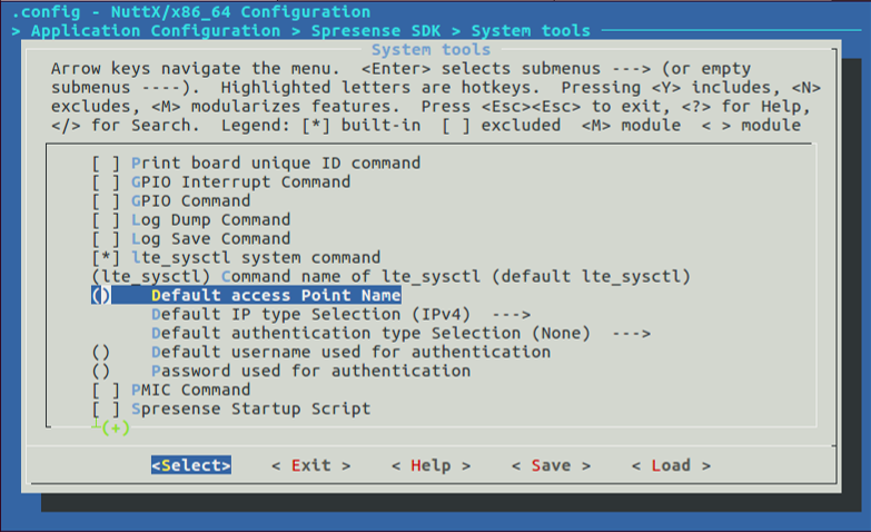
8.9.5. Instructions for enabling the factoryreset subcommand
Here are the steps to enable the factoryreset subcommand in lte_sysctl.
-
Open the menuconfig using tools/config.py.
tools/config.py -m -
Check
Enable factoryreset sub-command.Application Configuration -> Spresense SDK -> System tools -> lte_sysctl system command [*] Enable factoryreset sub-command

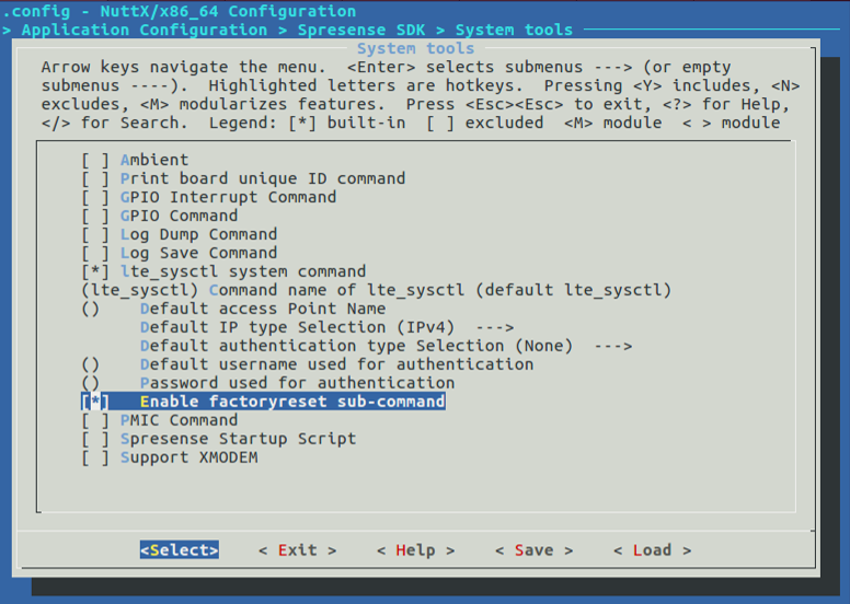
9. Filesystem Tutorials
9.1. SmartFS
This section describes the SmartFS used for the SPI-Flash filesystem.
Please refer to the following NuttX Wiki for more information of the SmartFS filesystem.
9.1.1. Initializing & mount
The board_flash_initialize() function is called from cxd56_bringup() during boot-up.
File: nuttx/boards/arm/cxd56xx/spresense/src/cxd56_bringup.c
#ifdef CONFIG_CXD56_SFC
ret = board_flash_initialize();
if (ret < 0)
{
_err("ERROR: Failed to initialize SPI-Flash. %d\n", errno);
}
#endifIn the board_flash_initialize() function, the SPI-Flash is initialized at the SmartFS filesystem
and is mounted on the /mnt/spif directory.
File: nuttx/boards/arm/cxd56xx/common/src/cxd56_flash.c
int board_flash_initialize(void)
{
int ret;
FAR struct mtd_dev_s *mtd;
mtd = cxd56_sfc_initialize(); (1)
if (!mtd)
{
ferr("ERROR: Failed to initialize SFC. %d\n ", ret);
return -ENODEV;
}
/* use the FTL layer to wrap the MTD driver as a block driver */
ret = ftl_initialize(CONFIG_SFC_DEVNO, mtd);
if (ret < 0)
{
ferr("ERROR: Initializing the FTL layer: %d\n", ret);
return ret;
}
#if defined(CONFIG_FS_SMARTFS)
/* Initialize to provide SMARTFS on the MTD interface */
ret = smart_initialize(CONFIG_SFC_DEVNO, mtd, NULL); (2)
if (ret < 0)
{
ferr("ERROR: SmartFS initialization failed: %d\n", ret);
return ret;
}
ret = mount("/dev/smart0d1", "/mnt/spif", "smartfs", 0, NULL); (3)
if (ret < 0)
{
ferr("ERROR: Failed to mount the SmartFS volume: %d\n", errno);
return ret;
}
#elif defined(CONFIG_FS_NXFFS)| 1 | Initialize the SPI-Flash to Memory Technology Device (MTD). |
| 2 | Initialize the MTD as the SmartFS filesystem. |
| 3 | Mount /dev/smart0d1 device file on /mnt/spif directory. |
9.1.2. Configuration
There are several configurations for using the SmartFS.
The following table shows the SDK default configuration (sdk/configs/default/defconfig).
| Configuration | Value | Description |
|---|---|---|
CONFIG_FS_SMARTFS |
y |
Enable the SmartFS filesystem. |
CONFIG_SMARTFS_ERASEDSTATE=0xff |
0xff |
It means erased state when SPI-Flash value is 0xFF. |
CONFIG_SMARTFS_MAXNAMLEN |
30 |
Max length of filename is 30. |
CONFIG_SMARTFS_MULTI_ROOT_DIRS |
y |
Supports for multi root directory, but uses a root directory in the default configuration. |
CONFIG_MTD_SMART |
y |
Use the SmartFS as the MTD. |
CONFIG_MTD_SMART_SECTOR_SIZE |
4096 |
The size of a sector is 4096 byte. Even a small file uses 4096 bytes (1 sector). Reducing this size will increase the number of files to be managed, but if you make it too small, the search process for the file will take a longer time. |
CONFIG_MTD_SMART_WEAR_LEVEL |
n |
If this is enabled, the file is periodically moved to a new sector as the sector rotation. In other words, the read-only files may be deleted by powered off during sector rotation. In case of power failure, it is recommended to disable this option. |
CONFIG_MTD_SMART_ENABLE_CRC |
y |
Use the CRC check for detecting bad sector. |
CONFIG_MTD_SMART_FSCK |
y |
The filesystem may be inconsistent by a power loss during a file operation. If this is enabled, it checks the filesystem at startup, and invalid files are deleted to preserve the integrity of the filesystem. |
CONFIG_MTD_SMART_MINIMIZE_RAM |
n |
This uses a cached table of logical-physical sector. If enabled, the performance of the filesystem is degraded. It is disabled by default. |
9.1.3. Operation check
You can check the filesystem by the df command on the NuttShell prompt.
nsh> df -h Filesystem Size Used Available Mounted on smartfs 4M 68K 4028K /mnt/spif procfs 0B 0B 0B /proc
Make sure that /mnt/spif is mounted as a smartfs filesystem, and
the total size is 4MByte, and you can check the used size and available size.
Create a new file.
nsh> echo "This is a test file." > /mnt/spif/test.txt
Check size of the file.
nsh> ls -l /mnt/spif /mnt/spif: -rw-rw-rw- 21 test.txt
Read the file.
nsh> cat /mnt/spif/test.txt This is a test file.
If you want to operate the file by programming, you can use low-level input/output functions such as open/read/write/close, or file input/output functions such as fopen/fread/fwrite/fclose.
9.1.4. How to format
The SPI-Flash is initialized for SmartFS filesystem by default.
If you want to clean up the SPI-Flash, you can use the mksmartfs command.
- Usage
nsh> help mksmartfs mksmartfs usage: mksmartfs [-s <sector-size>] [-f] <path> [<num-root-directories>]
- Example
nsh> mksmartfs -s 4096 -f /dev/smart0d1 1
After mksmartfs command, a few sectors are reserved for the root directory area and the remainder is available for user.
nsh> df -h Filesystem Size Used Available Mounted on smartfs 4M 28K 4068K /mnt/spif procfs 0B 0B 0B /proc
9.1.5. How to erase flash
If you cannot find a /dev/smart0d1 device file at startup,
or if you want to erase the SPI-Flash area used by your application,
you can use the flash_eraseall command.
To use the flash_eraseall command, enable CONFIG_SYSTEM_FLASH_ERASEALL in SDK configuration.
- Configuration
Application Configuration -> System Libraries and NSH Add-Ons FLASH Erase-all Command (CONFIG_SYSTEM_FLASH_ERASEALL)
- Usage
nsh> flash_eraseall usage: flash_eraseall flash_block_device
- Command
nsh> flash_eraseall /dev/mtdblock0
If you want to use the board as SmartFS after erasing the SPI-Flash, please reboot the board and then refer to the above-mentioned format procedure.
9.2. FAT file system
This section describes the FAT file system used for the SD card and eMMC.
9.2.1. Initializing & mount
The board_sdcard_initialize() and board_emmc_initialize() functions are called from cxd56_bringup() during boot-up.
File: nuttx/boards/arm/cxd56xx/spresense/src/cxd56_bringup.c
SD card
#ifdef CONFIG_CXD56_SDIO
ret = board_sdcard_initialize();
if (ret < 0)
{
_err("ERROR: Failed to initialize sdhci. \n");
}
#endifeMMC
#if defined(CONFIG_CXD56_EMMC) && !defined(CONFIG_CXD56_EMMC_LATE_INITIALIZE)
/* Mount the eMMC block driver */
ret = board_emmc_initialize();
if (ret < 0)
{
_err("ERROR: Failed to initialize eMMC: %d\n", ret);
}
#endifIn case of SD card
In the board_sdcard_initialize() function, set the GPIO interrupt to detect the insertion and removal of the SD card.
If the SD card is inserted, the board_sdcard_enable() function is called to initialize
the SD Host Controller and mount the SD card to the /mnt/sd0 directory.
If the SD card is removed, the board_sdcard_disable() function will be called
to terminate the SD host controller and unmount /mnt/sd0.
File: nuttx/boards/arm/cxd56xx/spresense/src/cxd56_sdcard.c
int board_sdcard_initialize(void)
{
#ifdef CONFIG_MMCSD_HAVE_CARDDETECT
/* Configure Interrupt pin with internal pull-up */
cxd56_pin_config(PINCONF_SDIO_CD_GPIO);
ret = cxd56_gpioint_config(PIN_SDIO_CD,
GPIOINT_PSEUDO_EDGE_FALL,
board_sdcard_detect_int,
NULL); (1)
:
}
static void board_sdcard_enable(FAR void *arg)
{
:
g_sdhci.sdhci = cxd56_sdhci_initialize(0); (2)
if (!stat("/dev/mmcsd0", &stat_sdio) == 0)
{
/* Now bind the SDHC interface to the MMC/SD driver */
ret = mmcsd_slotinitialize(0, g_sdhci.sdhci);
finfo("Successfully bound SDHC to the MMC/SD driver\n");
}
/* Handle the initial card state */
cxd56_sdhci_mediachange(g_sdhci.sdhci);
if (stat("/dev/mmcsd0", &stat_sdio) == 0)
{
if (S_ISBLK(stat_sdio.st_mode))
{
ret = mount("/dev/mmcsd0", "/mnt/sd0", "vfat", 0, NULL); (3)
}
}
:
}
static void board_sdcard_disable(FAR void *arg)
{
ret = umount("/mnt/sd0"); (4)
cxd56_sdhci_finalize(0); (5)
}| 1 | Set the GPIO interrupt for SD card insertion/ejection detection. |
| 2 | Initialize the SD Host Controller. |
| 3 | Mount /dev/mmcsd0 device to /mnt/sd0. |
| 4 | Unmount /mnt/sd0. |
| 5 | Finalize the SD Host Controller. |
In case of eMMC
In the board_emmc_initialize() function, the eMMC driver is initialized and the eMMC device is mounted to the /mnt/emmc directory.
On the other hand, the termination process unmounts the device by calling the board_emmc_finalize() function.
File: nuttx/boards/arm/cxd56xx/common/src/cxd56_emmcdev.c
int board_emmc_initialize(void)
{
/* Power on the eMMC device */
ret = board_power_control(POWER_EMMC, true); (1)
:
/* Initialize the eMMC device */
ret = cxd56_emmcinitialize(); (2)
:
/* Mount the eMMC device */
ret = nx_mount("/dev/emmc0", "/mnt/emmc", "vfat", 0, NULL); (3)
:
}
int board_emmc_finalize(void)
{
/* Un-mount the eMMC device */
ret = nx_umount2("/mnt/emmc", MNT_DETACH); (4)
:
/* Uninitialize the eMMC device */
ret = cxd56_emmcuninitialize(); (5)
:
/* Power off the eMMC device */
ret = board_power_control(POWER_EMMC, false); (6)
:
}| 1 | Turn the power on the eMMC. |
| 2 | Initialize the eMMC device. |
| 3 | Mount /dev/emmc0 device to /mnt/emmc. |
| 4 | Unmount /mnt/emmc. |
| 5 | Finalize the eMMC device. |
| 6 | Turn the power off the eMMC. |
9.2.2. Configuration
There are several configurations for using the FAT file system.
The following table shows the SDK default configuration.
| Configuration | Value | Description |
|---|---|---|
CONFIG_CXD56_SDIO |
y |
Enable SD card. |
CONFIG_CXD56_EMMC |
y |
Enable eMMC device. |
CONFIG_CXD56_EMMC_POWER_PIN_XXX |
y |
Select the pin for the eMMC power control. The default pin is PIN_I2S0_BCK. |
CONFIG_FS_FAT |
y |
Enable FAT file system. |
CONFIG_FAT_LCNAMES |
y |
Enable the upper/lower case of file name. |
CONFIG_FAT_LFN |
y |
Enable long file names. |
CONFIG_FAT_MAXFNAME |
64 |
Define maximum long file name. |
CONFIG_FS_FATTIME |
y |
Enable FAT date and time (timestamp). When the RTC is set to the current time (January 1, 1980 or later), the creation and modification dates of the file will be recorded. |
9.2.3. How to build
This is the build procedure via the command line.
When you use IDE, refer to the explanation of the following configuration.
-
Change directory to
sdkIf you do source
build-env.shscript, you can use the tab completion of theconfig.pytool.cd spresense/sdk source tools/build-env.sh
-
SDK configuration and building
tools/config.py device/sdcard (When using an SD card) tools/config.py device/emmc (When using an eMMC)
If the build is successful, a
nuttx.spkfile will be created under thesdkdirectory.make -
Flashing
nuttx.spkinto Spresense boardIn this case, the serial port is
/dev/ttyUSB0, and the baudrate of the uploading speed is500000bps. Please change according to your environment.tools/flash.sh -c /dev/ttyUSB0 -b 500000 nuttx.spk
9.2.4. Operation check
You can check the filesystem by the df command on the NuttShell prompt.
nsh> df -h Filesystem Size Used Available Mounted on vfat 14G 2762M 11G /mnt/sd0 smartfs 4M 28K 4068K /mnt/spif procfs 0B 0B 0B /proc
Make sure that /mnt/sd0 is mounted as a vfat filesystem, and
you can see the total (Size), used size (Used) and available size (Available).
Set RTC date and time to use the timestamp of file.
nsh> date -s "Feb 22 12:34:00 2021" nsh> date Feb 22 12:34:02 2021
Create a new file.
nsh> echo "This is a test file." > /mnt/sd0/test.txt
Check size of the file.
nsh> ls -l /mnt/sd0/test.txt -rw-rw-rw- 21 /mnt/sd0/test.txt
Read the file.
nsh> cat /mnt/sd0/test.txt This is a test file.
If you open the properties of the file in the SD card from your PC, you can confirm that the file timestamp is supported correctly.
If you want to operate the file by programming, you can use low-level input/output functions such as open/read/write/close, or file input/output functions such as fopen/fread/fwrite/fclose.
9.2.5. How to format
On your PC, use an SD memory card formatter to format the FAT file system.
exFAT file system is not supported.
|
If you want to format the SD card and eMMC device on the board, you can use the mkfatfs command.
nsh> help mkfatfs mkfatfs usage: mkfatfs [-F <fatsize>] [-r <rootdirentries>] <block-driver>
The procedure to format FAT32 is shown below.
SD card
nsh> mkfatfs -F 32 /dev/mmcsd0
eMMC
nsh> mkfatfs -F 32 /dev/emmc0
9.3. fsperf example application
This chapter describes how to use an example application fsperf to measure read/write performance on the filesystem.
9.3.1. How to build
This is the build procedure via the command line.
When you use IDE, refer to the explanation of the following configuration.
-
Change directory to
sdkIf you do source
build-env.shscript, you can use the tab completion of theconfig.pytool.cd spresense/sdk source tools/build-env.sh
-
SDK configuration and building
Execute the configuration by specifying
examples/fsperfas an argument ofconfig.py.
If the build is successful, anuttx.spkfile will be created under thesdkdirectory.tools/config.py examples/fsperf make
If you use an eMMC device, add
device/emmcto the argument.tools/config.py examples/fsperf device/emmc make
-
Flashing
nuttx.spkinto Spresense boardIn this case, the serial port is
/dev/ttyUSB0, and the baudrate of the uploading speed is500000bps. Please change according to your environment.tools/flash.sh -c /dev/ttyUSB0 -b 500000 nuttx.spk
9.3.2. Operation check
An example of running the fsperf command on the NuttShell prompt is shown below.
Run the fsperf command with the -f option and the path to the test file as arguments.
The specified path should be changed depending on the media to be measured.
First, the mkdir command creates the "temp" directory.
Finally, the rm command removes the entire directory of test files generated by fsperf.
SD card
nsh> mkdir /mnt/sd0/temp nsh> fsperf -f /mnt/sd0/temp/test File access speed monitor!! --- fwrite summary: Size: 1 [KB], Min: 4.064, Avg: 4.190, Max: 4.572 [Mbps] --- fwrite summary: Size: 2 [KB], Min: 1.954, Avg: 6.010, Max: 7.877 [Mbps] --- fwrite summary: Size: 4 [KB], Min: 14.028, Avg: 14.105, Max: 14.423 [Mbps] --- fwrite summary: Size: 8 [KB], Min: 23.541, Avg: 23.704, Max: 24.095 [Mbps] --- fwrite summary: Size: 16 [KB], Min: 34.713, Avg: 37.169, Max: 37.927 [Mbps] --- fwrite summary: Size: 32 [KB], Min: 18.833, Avg: 28.825, Max: 37.407 [Mbps] --- fwrite summary: Size: 64 [KB], Min: 21.817, Avg: 32.483, Max: 38.551 [Mbps] --- fwrite summary: Size: 128 [KB], Min: 27.149, Avg: 32.367, Max: 37.708 [Mbps] --- fwrite summary: Size: 256 [KB], Min: 27.026, Avg: 30.648, Max: 33.217 [Mbps] --- fwrite summary: Size: 512 [KB], Min: 18.553, Avg: 25.683, Max: 30.892 [Mbps] --- fwrite summary: Size: 1024 [KB], Min: 12.002, Avg: 22.746, Max: 29.715 [Mbps] --- fread summary: Size: 1 [KB], Min: 17.067, Avg: 18.156, Max: 18.286 [Mbps] --- fread summary: Size: 2 [KB], Min: 26.948, Avg: 27.235, Max: 28.445 [Mbps] --- fread summary: Size: 4 [KB], Min: 39.385, Avg: 39.691, Max: 40.961 [Mbps] --- fread summary: Size: 8 [KB], Min: 51.201, Avg: 51.201, Max: 51.201 [Mbps] --- fread summary: Size: 16 [KB], Min: 57.691, Avg: 57.854, Max: 58.515 [Mbps] --- fread summary: Size: 32 [KB], Min: 52.853, Avg: 53.058, Max: 53.196 [Mbps] --- fread summary: Size: 64 [KB], Min: 57.288, Avg: 57.428, Max: 57.489 [Mbps] --- fread summary: Size: 128 [KB], Min: 60.126, Avg: 60.192, Max: 60.236 [Mbps] --- fread summary: Size: 256 [KB], Min: 60.739, Avg: 60.773, Max: 60.795 [Mbps] --- fread summary: Size: 512 [KB], Min: 61.079, Avg: 61.080, Max: 61.089 [Mbps] --- fread summary: Size: 1024 [KB], Min: 61.350, Avg: 61.363, Max: 61.364 [Mbps] nsh> rm -r /mnt/sd0/temp
eMMC
nsh> mkdir /mnt/emmc/temp nsh> fsperf -f /mnt/emmc/temp/test File access speed monitor!! --- fwrite summary: Size: 1 [KB], Min: 6.564, Avg: 7.211, Max: 8.000 [Mbps] --- fwrite summary: Size: 2 [KB], Min: 11.637, Avg: 14.546, Max: 16.516 [Mbps] --- fwrite summary: Size: 4 [KB], Min: 26.257, Avg: 27.602, Max: 28.445 [Mbps] --- fwrite summary: Size: 8 [KB], Min: 43.575, Avg: 45.613, Max: 47.629 [Mbps] --- fwrite summary: Size: 16 [KB], Min: 57.691, Avg: 63.211, Max: 71.861 [Mbps] --- fwrite summary: Size: 32 [KB], Min: 67.149, Avg: 75.573, Max: 88.088 [Mbps] --- fwrite summary: Size: 64 [KB], Min: 55.352, Avg: 76.922, Max: 94.707 [Mbps] --- fwrite summary: Size: 128 [KB], Min: 77.103, Avg: 86.781, Max: 102.083 [Mbps] --- fwrite summary: Size: 256 [KB], Min: 79.247, Avg: 86.442, Max: 104.692 [Mbps] --- fwrite summary: Size: 512 [KB], Min: 80.168, Avg: 88.355, Max: 105.281 [Mbps] --- fwrite summary: Size: 1024 [KB], Min: 80.636, Avg: 88.837, Max: 100.904 [Mbps] --- fread summary: Size: 1 [KB], Min: 42.667, Avg: 58.183, Max: 64.001 [Mbps] --- fread summary: Size: 2 [KB], Min: 73.144, Avg: 80.002, Max: 85.335 [Mbps] --- fread summary: Size: 4 [KB], Min: 102.402, Avg: 102.402, Max: 102.402 [Mbps] --- fread summary: Size: 8 [KB], Min: 113.780, Avg: 119.768, Max: 120.473 [Mbps] --- fread summary: Size: 16 [KB], Min: 120.473, Avg: 123.749, Max: 124.124 [Mbps] --- fread summary: Size: 32 [KB], Min: 120.473, Avg: 121.007, Max: 122.271 [Mbps] --- fread summary: Size: 64 [KB], Min: 124.124, Avg: 125.743, Max: 126.033 [Mbps] --- fread summary: Size: 128 [KB], Min: 128.504, Avg: 128.504, Max: 128.504 [Mbps] --- fread summary: Size: 256 [KB], Min: 128.757, Avg: 128.969, Max: 129.010 [Mbps] --- fread summary: Size: 512 [KB], Min: 130.944, Avg: 131.048, Max: 131.074 [Mbps] --- fread summary: Size: 1024 [KB], Min: 130.748, Avg: 130.789, Max: 130.813 [Mbps] nsh> rm -r /mnt/emmc/temp
The fwrite summary shows the file writing speed (in Mbps), increasing the file size from 1 to 1024 KB, in the order of minimum, average, and maximum values. Then, the fread summary shows the file reading speed (in Mpbs).
The fsperf has the following command options.
nsh> fsperf
Usage: fsperf [-i] [-n <num>] -f <file>
FileSystem Performance Monitor:
-i: Display the information of each result
-n: Specify the repeat count, default is 10
-f: Specify the path to prefix of example files
e.g.
"-f /mnt/spif/test" on SPI-Flash
"-f /mnt/sd0/test" on SD card
"-f /mnt/emmc/test" on eMMC board
-i-
Specify when you want to display the individual results.
-n-
Specify the number of times to repeatedly read and write a file. The default is 10 times.
-f-
Specify the file path to prefix used by the
fsperf. Specify the path where the device to be measured is mounted, such as SPI-Flash, SD card or eMMC.
The following is an example when the -i option and the -n 3 are specified.
The three individual results are displayed before the summary line.
nsh> fsperf -f /mnt/sd0/temp/test -i -n 3
File access speed monitor!!
1 [KB] / 1.129 [ms], speed= 6.919 [Mbps]
1 [KB] / 1.068 [ms], speed= 7.314 [Mbps]
1 [KB] / 1.099 [ms], speed= 7.111 [Mbps]
--- fwrite summary: Size: 1 [KB], Min: 6.919, Avg: 7.111, Max: 7.314 [Mbps]
2 [KB] / 1.068 [ms], speed= 14.629 [Mbps]
2 [KB] / 1.038 [ms], speed= 15.059 [Mbps]
2 [KB] / 1.038 [ms], speed= 15.059 [Mbps]
--- fwrite summary: Size: 2 [KB], Min: 14.629, Avg: 14.913, Max: 15.059 [Mbps]
:
The results of running fsperf will vary depending on the type of SD card and the frequency of use.
Please measure the performance with the SD card you have.
10. HostIF Tutorials
10.1. HostIF example application
This chapter shows the usage of HostIF (Host Interface) example application.
This example application uses two Spresense boards. One is for the HostIF device, and another is for the Host. This can support the HostIF communication via I2C or SPI by connecting between Spresense boards. The example code also includes the implementation for the host.
10.1.1. Requirements
-
Spresense Main Board x2
-
Jumper wire
I2C connection diagram
Connect the I2C(#3) terminals on a B2B breakout board to the I2C(#0) terminals on a main board as the host.
The I/O voltage is 1.8V.
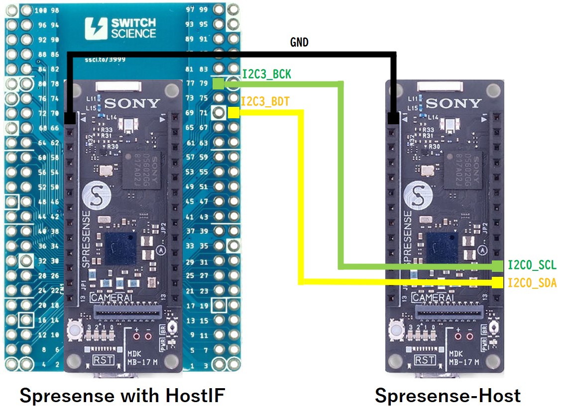
| B2B breakout | Host | ||
|---|---|---|---|
No. |
PAD name |
PAD name |
I/O voltage |
77 |
I2C3_BCK |
I2C0_SCL |
1.8V |
71 |
I2C3_BDT |
I2C0_SDA |
1.8V |
SPI connection diagram
Connect the SPI(#2) terminals on a B2B breakout board to the SPI(#5) terminals on a main board as the host.
The I/O voltage is 1.8V.
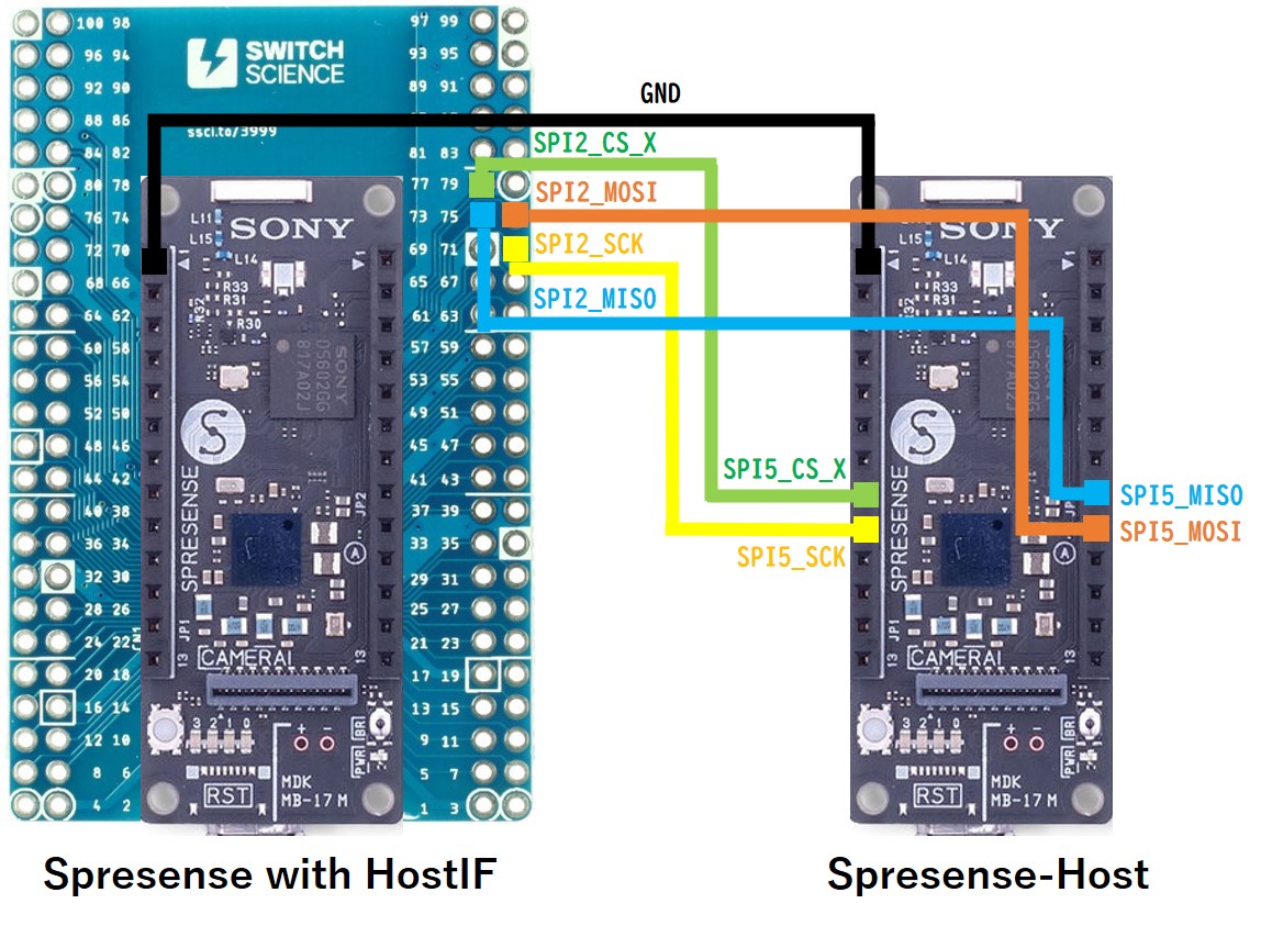
| B2B breakout | Host | ||
|---|---|---|---|
No. |
PAD name |
PAD name |
I/O voltage |
77 |
SPI2_CS_X |
SPI5_CS_X |
1.8V |
75 |
SPI2_MOSI |
SPI5_MOSI |
1.8V |
73 |
SPI2_MISO |
SPI5_MISO |
1.8V |
71 |
SPI2_SCK |
SPI5_SCK |
1.8V |
10.1.2. How to build
This is the build procedure via the command line.
When you use IDE, refer to the explanation of the following configuration.
-
Change directory to
sdkIf you do source
build-env.shscript, you can use the tab completion of theconfig.pytool.cd spresense/sdk source tools/build-env.sh
-
SDK configuration and building
Depending on the connection configuration, either I2C or SPI, execute the appropriate configuration.
If the build is successful, anuttx.spkfile will be created under thesdkdirectory.For I2C connection,
tools/config.py examples/hostif_i2c make
For SPI connection,
tools/config.py examples/hostif_spi make
-
Flashing
nuttx.spkinto both Spresense boardsIn this case, the serial port of a HostIF board is connected to
/dev/ttyUSB0and the one of a Host board is connected to/dev/ttyUSB1. The serial port number will change depending on the user environment.
The baudrate for uploading speed is set to 500000 bps. If it fails to upload, change the baudrate to 115200 bps.tools/flash.sh -c /dev/ttyUSB0 -b 500000 nuttx.spk tools/flash.sh -c /dev/ttyUSB1 -b 500000 nuttx.spk
10.1.3. Operation check
Open the serial terminals of both Spresense boards.
-
Open the serial terminal
This is an example of using a minicom terminal The serial port of a HostIF board is connected to
/dev/ttyUSB0and the one of a Host board is connected to/dev/ttyUSB1. The serial port number will change depending on the user environment. For both boards, set the baudrate to 115200 bps.minicom -D /dev/ttyUSB0 -b 115200 minicom -D /dev/ttyUSB1 -b 115200
-
Run
hostifcommand from NuttShell on the HostIF board.After initializing the HostIF driver,
write the build version to the HostIF communication buffer,
start a thread that writes a timestamp periodically to the HostIF communication buffer,
and start a thread that receives the data sent from the host and sends it back to the host.nsh> hostif Start updater: update the information periodically version: 0.0.0-SDK2.2.0-81ac8ad May 12 2021 15:53 Start loopback: loopback the received data
-
Run
host_i2corhost_spicommand from NuttShell on the host board.Receive the build version via I2C or SPI and output to the console,
send the data to the hostif board, receive the loop-backed data and output to the console.
Finally, receive the timestamps and output to the console.nsh> host_i2c version=0.0.0-SDK2.2.0-81ac8ad May 12 2021 15:53 (sz=41) Send done. 00 01 02 03 04 05 06 07 08 09 0a 0b 0c 0d 0e 0f Send done. 01 02 03 04 05 06 07 08 09 0a 0b 0c 0d 0e 0f 10 Send done. 02 03 04 05 06 07 08 09 0a 0b 0c 0d 0e 0f 10 11 Send done. 03 04 05 06 07 08 09 0a 0b 0c 0d 0e 0f 10 11 12 Send done. 04 05 06 07 08 09 0a 0b 0c 0d 0e 0f 10 11 12 13 Send done. 05 06 07 08 09 0a 0b 0c 0d 0e 0f 10 11 12 13 14 Send done. 06 07 08 09 0a 0b 0c 0d 0e 0f 10 11 12 13 14 15 Send done. 07 08 09 0a 0b 0c 0d 0e 0f 10 11 12 13 14 15 16 Send done. 08 09 0a 0b 0c 0d 0e 0f 10 11 12 13 14 15 16 17 Send done. 09 0a 0b 0c 0d 0e 0f 10 11 12 13 14 15 16 17 18 sec=15 nsec=85478117 (sz=8) sec=16 nsec=95518210 (sz=8) sec=17 nsec=105558303 (sz=8) sec=18 nsec=115598396 (sz=8) sec=19 nsec=125638489 (sz=8) sec=20 nsec=135678582 (sz=8) sec=21 nsec=145718675 (sz=8) sec=22 nsec=155758768 (sz=8) sec=23 nsec=165798861 (sz=8) sec=24 nsec=175838954 (sz=8)
10.1.4. Explanation of example code
This section explains the configuration of the communication buffer and the data contents in this example.
For detailed specification of HostIF, refer to SDK developer guide.
10.1.4.1. The configuration of the communication buffer.
Create a communication buffer to be sent from Host to Spresense (Index=0) and 3 communication buffers to be sent from Spresense to Host (Index=1,2,3).
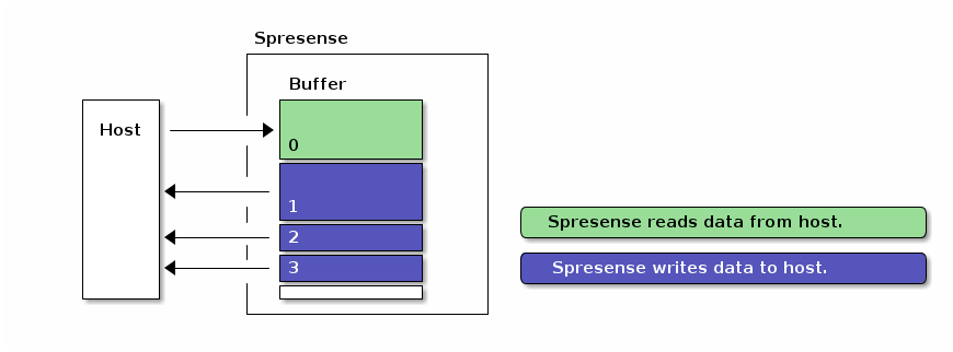
The purpose of each communication buffer is as below.
| Index | Size | Direction | Device filename | Description |
|---|---|---|---|---|
0 |
0x100 |
Read |
/dev/hostifr0 |
For loopback reception (general-purpose communication) |
1 |
0x100 |
Write |
/dev/hostifw1 |
For loopback transmission (for general-purpose communication) |
2 |
0x029 |
Write |
/dev/hostifw2 |
For sending the build version (for fixed data) |
3 |
0x008 |
Write |
/dev/hostifw3 |
For sending timestamps (for updated data on real-time) |
An example code for the buffer configuration is shown below.
#ifdef CONFIG_EXAMPLES_HOSTIF_I2C
static struct hostif_i2cconf_s conf =
#else
static struct hostif_spiconf_s conf =
#endif
{
#ifdef CONFIG_EXAMPLES_HOSTIF_I2C
.address = 0x24, /* own slave address */
#endif
.buff[0] =
{
/* BUFFER0: receive buffer from host */
0x100,
HOSTIF_BUFF_ATTR_READ | HOSTIF_BUFF_ATTR_VARLEN
},
.buff[1] =
{
/* BUFFER1: send buffer to host */
0x100,
HOSTIF_BUFF_ATTR_WRITE | HOSTIF_BUFF_ATTR_VARLEN
},
.buff[2] =
{
/* BUFFER2: send the constant version information */
VERSION_NAMELEN,
HOSTIF_BUFF_ATTR_WRITE | HOSTIF_BUFF_ATTR_FIXLEN
},
.buff[3] =
{
/* BUFFER3: send the variable timestamp information */
sizeof(struct timespec),
HOSTIF_BUFF_ATTR_WRITE | HOSTIF_BUFF_ATTR_FIXLEN
},
};10.1.4.2. HostIF operation
See the following link for example code on the HostIF side.
The processing flow of the example code is shown below.
-
Initialize the hostif driver with the specified buffer configuration.
#ifdef CONFIG_EXAMPLES_HOSTIF_I2C ret = hostif_i2cinitialize(&conf); #else ret = hostif_spiinitialize(&conf); #endif -
Start a
hostif_updaterthread.Write the build version obtained by
uname()to the Buffer(Index=2). It assume that the HostIF writes the information only once and then the host refers to it as fixed read-only data./* Write-once the constant software version to BUFFER2 */ struct utsname name; uname(&name); ret = write(wfd2, &name.version, VERSION_NAMELEN);Write the timestamp obtained by
clock_gettime()to Buffer(Index=3) every a second. It assumes that the HostIF periodically overwrites and updates the data, and the host always gets the latest data by reading asynchronously.struct timespec ts; clock_gettime(CLOCK_REALTIME, &ts); ret = write(wfd3, &ts, sizeof(ts)); -
Start a
hostif_loopbackthread.Receives the data sent from the Host via Buffer(Index=0), loops back and sends it to the host via Buffer(Index=1).
/* blocking read */ size = read(rfd, buffer, sizeof(buffer)); /* blocking write */ size = write(wfd, buffer, size);
10.1.4.3. Host operation
See the following links for example code on the Host side.
The processing flow of the example code is shown below.
-
Open the I2C or SPI driver.
/* Open the i2c driver */ fd = open("/dev/i2c0", O_WRONLY);/* Open the spi driver */ fd = open("/dev/spi5", O_WRONLY); -
Get the build version from Buffer(Index=2).
/* Get the version information from slave */ get_version(fd);In order for the host to be able to refer the fixed read-only data, the host set a lock-flag of the buffer on the communication protocol. By keeping the lock of the buffer, the HostIF is prohibited from updating, and the host is always readable.
-
The host sends the data to Buffer(Index=0) and receives the loop-backed data from Buffer(Index=1).
Repeat this behavior 10 times.
/* Loopback */ for (i = 0; i < 10; i++) { /* Send incremental data to slave */ send_data(fd); /* Wait a moment */ usleep(10 * 1000); /* Receive looped-back data */ receive_data(fd); } -
Get the timestamp from Buffer(Index=3).
Repeat this behavior 10 times every a second.
for (i = 0; i < 10; i++) { /* Get the timestamp from slave */ get_timestamp(fd); /* Wait a second until the timestamp is updated */ sleep(1); } -
Finally, close the I2C or SPI driver.
/* Close the i2c or spi driver */ close(fd);
11. FW Update Tutorials
11.1. FW Update example application
This chapter shows the usage of an example application to run firmware update.
Create a package.bin package file that concatenates the various firmware (SPK files) to be updated, and put it on the storage such as SPI-Flash or SD Card. You can update the firmwares by specifying the package file by the application.
11.1.1. How to build
This is the build procedure via the command line.
When you use IDE, refer to the explanation of the following configuration.
-
Change directory to
sdkIf you do source
build-env.shscript, you can use the tab completion of theconfig.pytool.cd spresense/sdk source tools/build-env.sh
-
SDK configuration and building
Execute the configuration by specifying
examples/fwupdateas an argument ofconfig.py.
If the build is successful, anuttx.spkfile will be created under thesdkdirectory.tools/config.py examples/fwupdate make
-
Flashing
nuttx.spkinto Spresense boardIn this case, the serial port is
/dev/ttyUSB0, and the baudrate of the uploading speed is500000bps. Please change according to your environment.tools/flash.sh -c /dev/ttyUSB0 -b 500000 nuttx.spk
11.1.2. How to create FW Update package
Use the package.sh script under the examples/fwupdate directory to create a package file package.bin that concatenates the firmwares to be updated.
To update nuttx.spk, loader.espk, and gnssfw.espk, specify multiple files as arguments of the package.sh script. If the script is successfully executed, it will create a package.bin file in the current directory.
cd spresense/sdk ../examples/fwupdate/package.sh nuttx.spk ../firmware/spresense/{loader,gnssfw}.espk Pack: 0 181392 nuttx.spk Pack: 1 129968 ../proprietary/spresense/bin/loader.espk Pack: 1 454512 ../proprietary/spresense/bin/gnssfw.espk ==================== Created package.bin ====================
It is also possible to create a single nuttx.spk package file as shown below.
../examples/fwupdate/package.sh nuttx.spk
Pack: 0 332512 nuttx.spk
====================
Created package.bin
====================
Transfer the created package.bin file to SPI-Flash.
./tools/flash.sh -c /dev/ttyUSB0 -w package.bin
xmodem
>>> Install files ...
nsh> xmodem /mnt/spif/package.bin
Install package.bin
|0%-----------------------------50%------------------------------100%|
######################################################################

nsh>
Transfer completed.
In this example, we transfer package.bin to the application area of SPI-Flash via USB serial.
For example, you can also transfer package.bin over the network such as WiFi or LTE, or use SD Card as the storage for package.bin.
11.1.3. Operation check
Open the serial terminal, and run fwupdate command.
-
Open the serial terminal
This is an example of using a minicom terminal with
/dev/ttyUSB0as the serial port and115200as the baudrate.minicom -D /dev/ttyUSB0 -b 115200 -
Type
fwupdatecommand on NuttShell promptThe usage of
fwupdatecommand is shown below.nsh> fwupdate FW Update Example!! Free space 1343488 bytes Usage: fwupdate [-f <filename>]... [-p <pkgname>] [-h] Description: FW Update operation Options: -f <filename>: update a file. -p <pkgname> : update a package. -z : update a package via USB CDC/ACM Zmodem. -h: Show this message
Free spaceshows the free space of the firmware storage area.Firmware update requires enough free space for redundancy. As a guide, the size of the package file specified by fwupdate should be less than half of this free space.
Run firmware update by specifying
package.binon SPI-Flash.nsh> fwupdate -p /mnt/spif/package.bin FW Update Example!! Free space 2449408 bytes File: /mnt/spif/package.bin Size: 765896 File: /mnt/spif/package.bin(0) Size: 181392 Type: FW_APP ->dl(0x2d03caf0, 65536 / 181392): ret=0 ->dl(0x2d03caf0, 131072 / 181392): ret=0 ->dl(0x2d03caf0, 181392 / 181392): ret=0 File: /mnt/spif/package.bin(1) Size: 129968 Type: FW_SYS ->dl(0x2d03caf0, 65536 / 129968): ret=0 ->dl(0x2d03caf0, 129968 / 129968): ret=0 File: /mnt/spif/package.bin(2) Size: 454512 Type: FW_SYS ->dl(0x2d03caf0, 65536 / 454512): ret=0 ->dl(0x2d03caf0, 131072 / 454512): ret=0 ->dl(0x2d03caf0, 196608 / 454512): ret=0 ->dl(0x2d03caf0, 262144 / 454512): ret=0 ->dl(0x2d03caf0, 327680 / 454512): ret=0 ->dl(0x2d03caf0, 393216 / 454512): ret=0 ->dl(0x2d03caf0, 454512 / 454512): ret=0 Package validation is OK. Saving package to "gnssfw" Package validation is OK. Saving package to "loader" Package validation is OK. Saving package to "nuttx" NuttShell (NSH) NuttX-10.1.0 nsh>
If the firmware update is successful, it will automatically reboot and boot with the new firmware.
Be careful not to reset or power off during the firmware update. If an error occurs during the reboot due to lack of free space or reset, the recovery process will run and the all of the firmware update in the package (in this case, gnssfw, loader, and nuttx) will be canceled, and the system will boot with the old firmware before updating.
12. System tools
Spresense SDK provides the system tools on NuttShell.
| Category | System tool | Description |
|---|---|---|
LOG |
A utility tool to change the log level dynamically |
|
A utility tool to dump the logging information on Backup SRAM |
||
A utility tool to save the logging information on Backup SRAM into SPI-Flash |
||
GPIO |
||
A utility tool for GPIO interrupt |
||
I2C |
A utility tool to communicate with I2C device |
|
PMIC |
||
USB |
||
Zmodem |
||
Stack |
A utility tool to monitor stack usages of all tasks and threads |
13. GPIO utility tool
This section describes the GPIO utility tool.
By using this tool, it’s possible to check the status of each pin and set the inputs and outputs to the GPIO pins.
13.1. How to build
This is the build procedure via the command line.
When you use IDE, refer to the explanation of the following configuration.
-
Change directory to
sdkIf you do source
build-env.shscript, you can use the tab completion of theconfig.pytool.cd spresense/sdk source tools/build-env.sh
-
SDK configuration and building
tools/config.py feature/gpiotool
make
If the build is successful, a
nuttx.spkfile will be created under thesdkdirectory. -
Flashing
nuttx.spkinto Spresense boardIn this case, the serial port is
/dev/ttyUSB0, and the baudrate of the uploading speed is500000bps. Please change according to your environment.tools/flash.sh -c /dev/ttyUSB0 -b 500000 nuttx.spk
13.2. Operation check
-
Open the serial terminal
This is an example of using a minicom terminal with
/dev/ttyUSB0as the serial port and115200as the baudrate.minicom -D /dev/ttyUSB0 -b 115200 -
Type
gpiocommand on NuttShell prompt. The usage is below.nsh> gpio -h USAGE: gpio command stat [<from_pin>] [<end_pin>] conf <pin> [-m <0|1|2|3>] [-i] [-H] [-p <0|1|2|3>] -m: function mode -i: input enable -H: Higher drive current/slew rate -p: 0=float, 1=pullup, 2=pulldown, 3=buskeeper read <pin> write <pin> <0|1|-1>
gpio statcommand can show the status of the specified pin.
gpio confcommand can configure the setting of the specified pin.
gpio readcommand can read a value from the specified pin.
gpio writecommand can write a value to the specified pin.
13.2.1. gpio stat command
gpio stat shows the status of all digital pins.
When the argument is specified, it shows the status from <from_pin> to <end_pin>.
nsh> gpio stat 97 100
-------------------------------------------------------------
( No)PIN NAME          : Mode I/O mA Pull Read IRQ Type NF EN
-------------------------------------------------------------
( 97)PIN_I2S1_BCK      : 0     /  2  --   0    -1
( 98)PIN_I2S1_LRCK     : 0     /  2  --   0    -1
( 99)PIN_I2S1_DATA_IN  : 0     /  2  --   0    -1
(100)PIN_I2S1_DATA_OUT : 0     /  2  --   0    -1
Mode-
Pin function mode.
Mode 0is used for GPIO function, andMode 1~3are used for functions other than GPIO, such as I2C and UART.
All the pins are divided into several groups, and the mode is set for each group.
For more information, refer to the SDK development guide Pin specification. I/O-
Inputmeans whether the input of pin is enabled or not.
Outputmeans whether the output of GPIO pin is enabled or not. mA-
Drive current (2mA or 4mA).
Pull-
--:Float,PU:Pull-Up,PD:Pull-Down,BK:Bus-Keeper Read-
A value read from the pin.
IRQ-
If the GPIO interrupt is set, it means the IRQ number.
Type-
If the GPIO interrupt is set, it means the interrupt polarity.
(High:Level,Low:Level,Rise:Rising Edge,Fall:Falling Edge,Both:Both Edge) NF-
If the GPIO interrupt is set, it means enable or disable of the noise filter to prevent chattering.
EN-
If the GPIO interrupt is set, it means enable or disable of the interrupt.
13.2.2. gpio conf command
The gpio conf command can alter the function modes and input/output settings for the specified pin number.
If type gpio conf 37 -m 0 -i -p 2, PIN_SEN_IRQ_IN (No. 37) pin is set to the GPIO function mode, input-enabled, and pull-down.
nsh> gpio conf 37 -m 0 -i -p 2
nsh> gpio stat 37
-------------------------------------------------------------
( No)PIN NAME          : Mode I/O mA Pull Read IRQ Type NF EN
-------------------------------------------------------------
( 37)PIN_SEN_IRQ_IN    : 0    I/  2  PD   0    -1
13.2.3. gpio read command
gpio read command reads a value from the port of the specified pin number.
If type gpio read 37, then PIN_SEN_IRQ_IN (No.37) pin is read and the result displays 0 (LOW) or 1 (HIGH).
nsh> gpio read 37
0
nsh> gpio read 37
1
13.2.4. gpio write command
gpio write command writes 0 (LOW), 1 (HIGH) or -1 (HiZ) to the port of the specified pin number.
PIN_I2S1_BCK(No.97) pin is connected to LED0 on the main board.
If type gpio write 97 1, it turns LED0 on. If type gpio write 97 0, it turns LED0 off.
nsh> gpio write 97 1
nsh> gpio write 97 0
13.3. Programming
13.3.1. GPIO API
See API Reference Manual for the details of the GPIO API.
To use the GPIO API, include the following files.
#include <arch/board/board.h>
#include <arch/chip/pin.h>
The prototype declarations of the GPIO API are defined:
nuttx/boards/arm/cxd56xx/spresense/include/cxd56_gpioif.h
The pin names used by the GPIO API are defined:
nuttx/arch/arm/include/cxd56xx/pin.h
13.3.2. GPIO input setting
This section shows how to input from the GPIO pin.
  /* Input pin settings */

  board_gpio_config(PIN_XXX, 0, true, false, PIN_FLOAT);     (1)
  board_gpio_config(PIN_XXX, 0, true, false, PIN_PULLUP);    (2)
  board_gpio_config(PIN_XXX, 0, true, false, PIN_PULLDOWN);  (3)
  board_gpio_config(PIN_XXX, 0, true, false, PIN_BUSKEEPER); (4)

  /* Input pin */

int status = board_gpio_read(PIN_XXX); (5)| 1 | PIN_XXX is input-enabled. |
| 2 | PIN_XXX is input-enabled with pull-up. |
| 3 | PIN_XXX is input-enabled with pull-down. |
| 4 | PIN_XXX is input-enabled with bus-keeper. |
| 5 | Read a value from PIN_XXX. |
13.3.3. GPIO output setting
This section shows how to output to the GPIO pin.
  /* Output pin setting */

  board_gpio_config(PIN_XXX, 0, false, true,  PIN_FLOAT); (1)
  board_gpio_config(PIN_XXX, 0, false, false, PIN_FLOAT); (2)

  /* Output pin */

  board_gpio_write(PIN_XXX, 0);   (3)
  board_gpio_write(PIN_XXX, 1);   (4)
board_gpio_write(PIN_XXX, -1); (5)| 1 | PIN_XXX is input-disabled. The drive current of the pin is set to 4mA. |
| 2 | PIN_XXX is input-disabled. The drive current of the pin is set to 2mA. |
| 3 | Write LOW to PIN_XXX. |
| 4 | Write HIGH to PIN_XXX. |
| 5 | Disable the output of PIN_XXX. |
13.3.4. GPIO interrupt setting
This section shows how to use the GPIO interrupt.
static int gpio_handler(int irq, FAR void *context, FAR void *arg)
{
  /* Interrupt handler */
}

  /* Interrupt setting */

  board_gpio_intconfig(PIN_XXX, INT_HIGH_LEVEL,  false, gpio_handler); (1)
  board_gpio_intconfig(PIN_XXX, INT_LOW_LEVEL,   false, gpio_handler); (2)
  board_gpio_intconfig(PIN_XXX, INT_RISING_EDGE,  true, gpio_handler); (3)
  board_gpio_intconfig(PIN_XXX, INT_FALLING_EDGE, true, gpio_handler); (4)
  board_gpio_intconfig(PIN_XXX, INT_BOTH_EDGE,    true, gpio_handler); (5)

  board_gpio_int(PIN_XXX, false); (6)
board_gpio_int(PIN_XXX, true); (7)| 1 | The interrupt polarity of PIN_XXX is set to HIGH level. The interrupt handler is registered. |
| 2 | The interrupt polarity of PIN_XXX is set to LOW level. The interrupt handler is registered. |
| 3 | The interrupt polarity of PIN_XXX is set to rising edge. The interrupt handler is registered. The Noise filter is enabled. |
| 4 | The interrupt polarity of PIN_XXX is set to falling edge. The interrupt handler is registered. The Noise filter is enabled. |
| 5 | The interrupt polarity of PIN_XXX is set to both edge. The interrupt handler is registered. The Noise filter is enabled. |
| 6 | Disable the interrupt of PIN_XXX. |
| 7 | Enable the interrupt of PIN_XXX. |
14. PMIC utility tool
This section describes the PMIC utility tool.
By using this tool, it’s possible to set the load-switch and GPOs on PMIC(CXD5247).
14.1. How to build
This is the build procedure via the command line.
When you use IDE, refer to the explanation of the following configuration.
-
Change directory to
sdkIf you do source
build-env.shscript, you can use the tab completion of theconfig.pytool.cd spresense/sdk source tools/build-env.sh
-
SDK configuration and building
tools/config.py feature/pmictool
make
If the build is successful, a
nuttx.spkfile will be created under thesdkdirectory. -
Flashing
nuttx.spkinto Spresense boardIn this case, the serial port is
/dev/ttyUSB0, and the baudrate of the uploading speed is500000bps. Please change according to your environment.tools/flash.sh -c /dev/ttyUSB0 -b 500000 nuttx.spk
14.2. Operation check
-
Open the serial terminal
This is an example of using a minicom terminal with
/dev/ttyUSB0as the serial port and115200as the baudrate.minicom -D /dev/ttyUSB0 -b 115200 -
Type
pmiccommand on NuttShell prompt. The usage is below.nsh> pmic -h Usage: pmic [-h] [-l] [-e <target>] [-d <target>] [-r <addr>] [-w <addr> -v <value>] Description: PMIC utility tool Options: -l: Show power status of the target -e <target>: Enable power to the target -d <target>: Disable power to the target -z <target>: Set GPO to HiZ to the target -r <addr>: Single read from <addr> -w <addr> -v <value>: Single write <value> to <addr> -h: Show this messagepmic -lshows the list of status.nsh> pmic -l Target Name : on/off ----------- : ------ DDC_IO : on LDO_EMMC : on DDC_ANA : off LDO_ANA : on DDC_CORE : on LDO_PERI : off LSW2 : off LSW3 : on LSW4 : on GPO0 : hiz GPO1 : off GPO2 : off GPO3 : off GPO4 : off GPO5 : off GPO6 : off GPO7 : offIf type
pmic -e GPO0, then set enable to GPO0.
If typepmic -d GPO0, then set disable to GPO0.
If typepmic -z GPO0, then set Hi-Z to GPO0.
14.3. Connection
Load switches (LSW) and GPOs are mainly used for various power controls.
It shows a list of connections on the main board or extension board.
| DDC_CORE, DDC_IO, and LDO_ANA are connected to CORE, IO, and analog power supply of the processor, respectively. These should not be disabled. The description of LDO_PERI is omitted because it is not connected to the board. |
| Target | Voltage | Main board | Extension board | LTE extension board |
|---|---|---|---|---|
LDO_EMMC |
3.3V |
pin socket 3.3V |
- |
- |
LSW2 |
1.8V |
Audio DVDD |
- |
- |
LSW3 |
SPI-Flash |
- |
- |
|
LSW4 |
TCXO 26MHz |
- |
- |
|
GPO0 |
VSYS(4.0V) |
- |
- |
3.3V LDO |
GPO1 |
- |
Audio 3.3V LDO |
||
GPO2 |
- |
- |
LTE DCDC |
|
GPO3 |
- |
- |
(LTE VBAT) |
|
GPO4 |
Camera LDO |
- |
- |
|
GPO5 |
- |
- |
- |
|
GPO6 |
- |
Audio Headphone Amp. |
||
GPO7 |
- |
- |
- |
|
14.4. Programming
14.4.1. PMIC API
To use the PMIC API, include the following files.
#include <arch/board/board.h>The prototype declarations of the PMIC API are defined:
nuttx/boards/arm/cxd56xx/spresense/include/cxd56_power.h
The target names used by the PMIC API are defined in the board-dependent files with aliases such as POWER_LTE.
nuttx/boards/arm/cxd56xx/spresense/include/board.h
14.4.2. GPO output setting
This section shows how to output to the GPO pin.
To turn it on or off, you can use either board_power_control() or board_power_control_tristate().
Use the board_power_control_tristate() function if you want to set it to HiZ.
  /* GPO output */

  board_power_control(PMIC_GPO(0), true);  (1)
  board_power_control(PMIC_GPO(0), false); (2)

  board_power_control_tristate(PMIC_GPO(0), 1);  (3)
  board_power_control_tristate(PMIC_GPO(0), 0);  (4)
board_power_control_tristate(PMIC_GPO(0), -1); (5)| 1 | Enable GPO0 |
| 2 | Disable GPO0 |
| 3 | Enable GPO0 |
| 4 | Disable GPO0 |
| 5 | Set Hi-Z to GPO0 |
14.4.3. GPO monitor
This section shows how to monitor from the GPO pin.
To read 2-state (on or off), you can use either board_power_monitor() or board_power_monitor_tristate().
Use the board_power_monitor_tristate() function if you want to read 3-state (on, off, or HiZ).
  /* GPO monitor */

  bool bstate = board_power_monitor(PMIC_GPO(0)); (1)

int istate = board_power_monitor_tristate(PMIC_GPO(0)); (2)| 1 | Read GPO0. If the result is true, it means Enable. Otherwise false, it means Disable. |
| 2 | Read GPO0. The result is 1 for Enable, 0 for Disable, -1 for Hi-Z. |
15. USB MSC system tool
This section describes the utility tool to use USB MSC (Mass Storage Class) feature.
When the USB MSC function is enabled, the Host PC can directly access the SD card on the Spresense board.
15.1. How to build
This is the build procedure via the command line.
When you use IDE, refer to the explanation of the following configuration.
-
Change directory to
sdkIf you do source
build-env.shscript, you can use the tab completion of theconfig.pytool.cd spresense/sdk source tools/build-env.sh
-
SDK configuration and building
Since the SD card is mounted as a USB MSC, open the menuconfig with the SD card function enabled.
tools/config.py feature/usbmsc
make
If the build is successful, a
nuttx.spkfile will be created under thesdkdirectory. -
Flashing
nuttx.spkinto Spresense boardIn this case, the serial port is
/dev/ttyUSB0, and the baudrate of the uploading speed is500000bps. Please change according to your environment.tools/flash.sh -c /dev/ttyUSB0 -b 500000 nuttx.spk
15.2. Operation check
With the SD card inserted in the extension board, connect the USB connector of the extension board to the Host PC with a USB cable.
-
Open the serial terminal
This is an example of using a minicom terminal with
/dev/ttyUSB0as the serial port and115200as the baudrate.minicom -D /dev/ttyUSB0 -b 115200 -
Type
msconncommand on NuttShell promptnsh> msconn mcsonn_main: Creating block drivers mcsonn_main: Configuring with NLUNS=1 mcsonn_main: handle=d038d50 mcsonn_main: Bind LUN=0 to /dev/mmcsd0 mcsonn_main: Connected
The new removable disk is recognized by the Host PC, and the contents of the SD card on the extension board can be accessed from the Host PC.
-
To terminate the USB MSC function, type
msdiscommand on NuttShell prompt.nsh> msdis msdis: Disconnected
16. USB CDC/ACM system tool
This section describes the utility tool to use USB CDC/ACM feature.
When the USB CDC/ACM function is enabled, the USB of the extension board can be used as a serial port.
16.1. How to build
This is the build procedure via the command line.
When you use IDE, refer to the explanation of the following configuration.
-
Change directory to
sdkIf you do source
build-env.shscript, you can use the tab completion of theconfig.pytool.cd spresense/sdk source tools/build-env.sh
-
SDK configuration and building
Open the menuconfig.
tools/config.py feature/usbcdcacm
make
If the build is successful, a
nuttx.spkfile will be created under thesdkdirectory. -
Flashing
nuttx.spkinto Spresense boardIn this case, the serial port is
/dev/ttyUSB0, and the baudrate of the uploading speed is500000bps. Please change according to your environment.tools/flash.sh -c /dev/ttyUSB0 -b 500000 nuttx.spk
16.2. Operation check
Connect the USB connector of the extension board to the Host PC with a USB cable.
-
Open the serial terminal
This is an example of using a minicom terminal with
/dev/ttyUSB0as the serial port and115200as the baudrate.minicom -D /dev/ttyUSB0 -b 115200 -
Type
serconcommand on NuttShell promptnsh> sercon sercon: Registering CDC/ACM serial driver sercon: Successfully registered the CDC/ACM serial driver
The new device file
/dev/ttyACM0is generated on the Spresense board, and a new COM port can be found on the Host PC. You can use this port for serial communication via USB. -
To terminate the USB CDC/ACM function, type
serdiscommand on NuttShell prompt.nsh> serdis serdis: Disconnected
17. Zmodem file transfer
This section describes how to send and receive files between Host PC and Spresense board using Zmodem transfer.
17.1. How to build
This is the build procedure via the command line.
When you use IDE, refer to the explanation of the following configuration.
-
Change directory to
sdkIf you do source
build-env.shscript, you can use the tab completion of theconfig.pytool.cd spresense/sdk source tools/build-env.sh
-
SDK configuration and building
Execute the configuration by specifying
feature/zmodemas an argument ofconfig.py.
If the build is successful, anuttx.spkfile will be created under thesdkdirectory.tools/config.py feature/zmodem make
-
Flashing
nuttx.spkinto Spresense boardIn this case, the serial port is
/dev/ttyUSB0, and the baudrate of the uploading speed is500000bps. Please change according to your environment.tools/flash.sh -c /dev/ttyUSB0 -b 500000 nuttx.spk
17.2. Operation check
Use a serial terminal that supports the Zmodem transfer.
This is using minicom terminal for a example.
If minicom and lrzsz are not installed, install them in advance.
sudo apt install minicom lrzsz
Open a minicom terminal with /dev/ttyUSB0 as the serial port and 115200 as the baudrate.
minicom -D /dev/ttyUSB0 -b 115200
You can use Zmodem’s rz (receive) and sz (send) commands on NuttShell prompt.
- The usage of rz command
-

- The usage of sz command
-

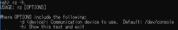
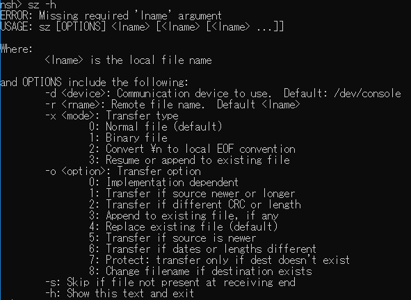
17.2.1. File transfer from Host PC to Spresense board
How to transfer files from the HostPC to the Spresense board is shown below.
-
On minicom terminal, type
CTRL-aandzkey, and open the menu (This shortcut key assignment can be changed by the user. See the minicom manual for details.)
Then press theskey and select Send files.
-
Select zmodem with cursor key and execute with
Enterkey.
-
Move the folder with the cursor key and the space key, and select the file you want to transfer.
Select a folder with the cursor keys and press the space key twice to move to the folder.
Select the file with the cursor keys and the space key, and press theEnterkey to start the transfer.
Alternatively, you can press the
Enterkey and input the file name to execute the transfer.
-
The file transfer starts and the transfer is completed when "Transfer complete" is displayed.

-
The transfer destination of the file on the Spresense board can be changed with CONFIG_SYSTEM_ZMODEM_MOUNTPOINT.
In the default configuration, files are transferred to Flash of/mnt/spif.
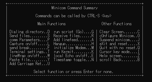
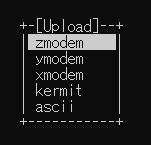
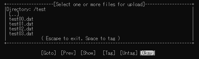
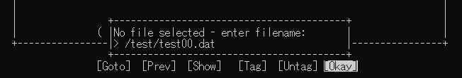
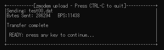
If you use TeraTerm terminal, you can send the selected file from File→ Transfer→ ZMODEM→ Send from TeraTerm menu.
|
17.2.2. File transfer from Spresense board to Host PC
How to transfer files from the Spresense board to the HostPC is shown below.
-
On NuttShell prompt, specify the file you want to transfer to the argument of the
szcommand.
Enter the full path name starting with/.
The following example uses the-x 1binary transfer option.nsh> sz -x 1 /mnt/spif/test00.dat
-
The file transfer starts and the transfer is completed when "Transfer complete" is displayed.

-
The file is transferred into the folder where minicom was executed on the Host PC.
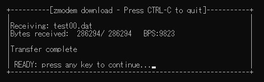
If you use TeraTerm terminal, you can receive the file from File→ Transfer→ ZMODEM→ Receive of TeraTerm menu.
|
18. How to start applications automatically
This chapter describes how to start the user application automatically instead of the NuttShell prompt on power up. NuttShell allows you to run simple shell scripts and can run specific scripts at startup. In this chapter, we will explain automatic startup using that function. See NuttShell (NSH) documentation for basic commands that can be used on NuttShell and control syntax such as if and while.
18.1. Using Startup Scripts with Spresense SDK
In order to use autostart scripts in NuttX, you need to enable that feature in your configurations. Spresense SDK provides a default configuration to enable autostart.
As an example, let’s create a startup script that uses the hello built-in command to display the string "hello" every three seconds after startup.
18.1.1. Configuration
First, configure the SDK with the hello built-in command used in this example and the default config that enables autostart.
Go to the spresense/sdk directory and run config.py with two parameters as follows.
./tools/config.py examples/hello feature/startup_script
The first parameter examples/hello is an option to enable the hello built-in command and the second parameter feature/startup_script is an option to enable the autostart mechanism.
| In this way, in the config.py script of Spresense SDK, it is possible to add default configs prepared for the SDK by adding various parameters. |
18.1.2. Build and Flash
After completing the configuration, execute the following command under the same spresense/sdk directory to write nuttx.spk to the board.
tools/flash.sh -c /dev/ttyUSB0 nuttx.spk >>> Install files ... install -b 115200 Install nuttx.spk |0%-----------------------------50%------------------------------100%| ###################################################################### xxxxx bytes loaded. Package validation is OK. Saving package to "nuttx" updater# sync updater# Restarting the board ... reboot
18.1.3. Operation check (without automatic start)
Just writing nuttx.spk will not start your application automatically. First, let’s check if the nuttx.spk we wrote contains the hello built-in command correctly.
Open the serial terminal using a suitable terminal software (minicom is used in the example below). In this case, the serial port is /dev/ttyUSB0, but please change according to your environment.
minicom -D /dev/ttyUSB0 -b 115200
When connecting to the Spresense board, the following message appears along with the nsh> prompt.
No /mnt/spif/init.rc. NuttShell (NSH) NuttX-8.2 nsh>
| It seems that some terminals do not reset the board when connected. The above message is displayed immediately after resetting, so if it does not appear, try pressing the reset button on the Spresense board while keeping the terminal connected. |
If you hit "help" in this state, you can confirm that hello is in Builtin Apps: as shown below.
nsh> help help usage: help [-v] [<cmd>] [ dirname free mb mv set unset ? date help mkdir mw sh usleep basename dd hexdump mkfatfs poweroff sleep xd break df ifconfig mkfifo ps test cat echo ifdown mkrd pwd time cd exec ifup mksmartfs reboot true cp exit kill mh rm uname cmp false ls mount rmdir umount Builtin Apps: hello nsh nsh>
Now run hello to see how it works.
nsh> hello Hello, World!! nsh>
Now we have confirmed that hello works. Next, we will create a script that executes this app every three seconds.
18.1.4. Operation check (automatic start)
After confirming the operation of hello in the previous section, exit the terminal and create a script file.
Name the script file init.rc. Create a script like the one below.
while true do sleep 3 hello done
This simple script uses while true to create an infinite loop which repeatedly waits three seconds then executes hello.
Write this script to the SPI flash of the Spresense mainboard. Assuming that init.rc is in the spresense/sdk directory, execute a command like the following in the spresense/sdk directory.
./tools/flash.sh -w init.rc xmodem >>> Install files ... nsh> xmodem /mnt/spif/init.rc Install init.rc |0%-----------------------------50%------------------------------100%| ###################################################################### nsh>
By using the -w option, flash.sh writes the file specified in subsequent arguments to the actual SPI flash.
If you run flash.sh with -w you will have to rewrite nuttx.spk. There is already a prebuilt nuttx.spk in spresense/sdk so write it again.
tools/flash.sh -c /dev/ttyUSB0 nuttx.spk >>> Install files ... install -b 115200 Install nuttx.spk |0%-----------------------------50%------------------------------100%| ###################################################################### xxxxx bytes loaded. Package validation is OK. Saving package to "nuttx" updater# sync updater# Restarting the board ... reboot
In this state, try to connect to the terminal again.
Run /mnt/spif/init.rc. sh [8:100] NuttShell (NSH) NuttX-8.2 nsh> Hello, World!! Hello, World!! Hello, World!! Hello, World!! Hello, World!!
Once connected, you can see that the message "Hello, World!!" is displayed every three seconds, as intended.
18.2. SDK Entrypoint
There is another way to start the application automatically that uses the CONFIG_INIT_ENTRYPOINT configuration instead of the startup script.
The default configuration of CONFIG_INIT_ENTRYPOINT is spresense_main, but
if you change it to hello_main, then the hello application would be launched on startup.
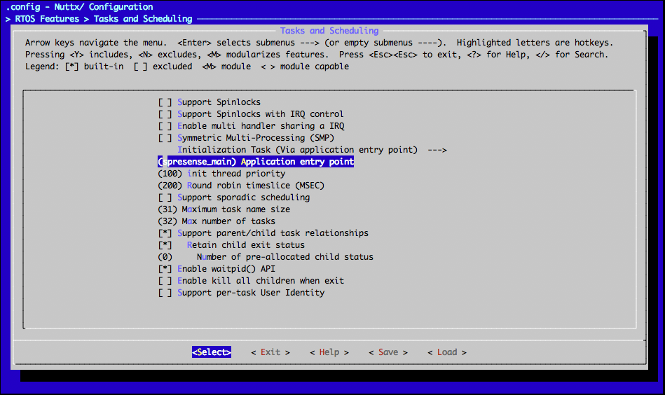
| The entry point function name is the string in the PROGNAME variable defined in the Makefile of the sample code with _main appended. Example: In spresense/sdk/apps/examples/hello/Makefile, the definition of PROGNAME is $(CONFIG_EXAMPLES_HELLO_PROGNAME). The name is fixed in the Kconfig parameter, and if you look at spresense/sdk/apps/examples/Kconfig, the config EXAMPLES_HELLO_PROGNAME column says default "hello". In this case, PROGNAME is hello, so "hello_main" is the entry function name. |
| The application needs to be initialized at startup. Add #include <sys/boardctl.h> and boardctl(BOARDIOC_INIT, 0) into the user entrypoint function. |
#include <sys/boardctl.h>
#ifdef CONFIG_BUILD_KERNEL
int main(int argc, FAR char *argv[])
#else
int hello_main(int argc, char *argv[])
#endif
{
/* Initialize apllication */
boardctl(BOARDIOC_INIT, 0);
printf("Hello, World!!\n");
return 0;
}19. Loadable ELF tutorial
Loadable ELF is the ability to create the OS and application in separate binaries and load and run the application dynamically.
When an application is created as a loadable ELF, it can be loaded into memory as needed, thus reducing the total amount of memory at runtime or allowing the application to be updated independently. However, it is important to note that the start-up time of the application may become longer and memory fragmentation may occur due to repeated loading/unloading.
| Loadable ELF is different from ASMP ELF. The application to be launched runs only on the main core. |
In this tutorial, we will use an SD card as the storage location for the ELF files in our application.
19.1. How to build
This is the build procedure via the command line.
When you use IDE, refer to the explanation of the following configuration.
-
Change directory to
sdkIf you do source
build-env.shscript, you can use the tab completion of theconfig.pytool.cd spresense/sdk source tools/build-env.sh
-
SDK configuration and building
Execute the configuration by specifying
feature/loadableanddevice/sdcardas an argument ofconfig.py.tools/config.py feature/loadable device/sdcard tools/config.py -m
Open the menu config and activate the
Hello, World! example. At this time, the application will be built as a loadable ELF ifHello, World! exampleis set toM.[Application Configuration] [Examples] ["Hello, World!" example] => MWhen the configuration is complete, build it.
makeWhen the build is complete, a
nuttx.spkfile will be created under thesdkfolder, and an ELF filehellowill be created undersdk/apps/bin. You should copyhelloto the SD card separately. -
Flashing
nuttx.spkinto Spresense boardIn this case, the serial port is
/dev/ttyUSB0, and the baudrate of the uploading speed is500000bps. Please change according to your environment.tools/flash.sh -c /dev/ttyUSB0 -b 500000 nuttx.spk
19.2. Operation check
Open the serial terminal, and run hello application.
-
Open the serial terminal
This is an example of using a minicom terminal with
/dev/ttyUSB0as the serial port and115200as the baudrate.minicom -D /dev/ttyUSB0 -b 115200 -
Execute
helloapplication on NuttShell promptSpecify the full path to the
helloELF file on the SD card.nsh> /mnt/sd0/hello Hello, World!!
19.3. Using the PATH environment variable
NuttShell can set the path of an ELF file using the PATH environment variable as well as the environment variable of bash. The feature/loadable contains settings to use it, but the actual path to use must be set by the user.
Open the menu config and set the PATH environment variable to the path of the SD card. With this setting, applications located directly underneath the SD card will be able to run without specifying the full path.
[Binary Loader] [Initial PATH Value] => "/mnt/sd0"
Build it and flush nuttx.spk. You can launch hello applications on SD card by typing hello from NuttShell.
nsh> hello Hello, World!!
20. LLVM C++ Standard Library
This section describes how to use the LLVM C++ standard library from user application. Because the LLVM source code is downloaded and compiled during the build process, please run the build in an environment with a network connection.
You need to update your compiler version to gcc-arm-none-eabi-9-2019-q4-major or later.
If the compiler version is old, please refer to Development environment to update your compiler.
|
20.1. How to build
This is the build procedure via the command line.
When you use IDE, refer to the explanation of the following configuration.
-
Change directory to
sdkIf you do source
build-env.shscript, you can use the tab completion of theconfig.pytool.cd spresense/sdk source tools/build-env.sh
-
SDK configuration and building
Run the configuration by adding
feature/libcxxas an argument, in addition to applications such asexamples/helloxx. And, to run the C++ test program, add the-moption and open menuconfig.tools/config.py examples/helloxx feature/libcxx -mEnable
Application Configuration→Testing→C++ test program.
Because the SDK disables RTTI (Run-Time Type Information) by adding
-fno-rttias a compile option, open the filesdk/apps/testing/cxxtest/cxxtest_main.cxxand comment outtest_rtti().diff --git a/testing/cxxtest/cxxtest_main.cxx b/testing/cxxtest/cxxtest_main.cxx index 6baa7d3..288aa40 100644 --- a/testing/cxxtest/cxxtest_main.cxx +++ b/testing/cxxtest/cxxtest_main.cxx @@ -184,6 +184,7 @@ static void test_stl(void) static void test_rtti(void) { +#ifdef __GXX_RTTI std::cout << "test rtti===============================" << std::endl; Base *a = new Base(); Base *b = new Extend(); @@ -199,6 +200,7 @@ static void test_rtti(void) delete a; delete b; +#endif } //***************************************************************************If the build is successful, a
nuttx.spkfile will be created under thesdkdirectory.make -
Flashing
nuttx.spkinto Spresense boardIn this case, the serial port is
/dev/ttyUSB0, and the baudrate of the uploading speed is500000bps. Please change according to your environment.tools/flash.sh -c /dev/ttyUSB0 -b 500000 nuttx.spk
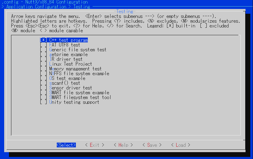
20.2. Operation check
-
Open the serial terminal
This is an example of using a minicom terminal with
/dev/ttyUSB0as the serial port and115200as the baudrate.minicom -D /dev/ttyUSB0 -b 115200 -
Type
cxxtestcommand on NuttShell promptnsh> cxxtest test ofstream=========================== printf: Starting test_ostream printf: Successfully opened /dev/console cout: Successfully opened /dev/console Writing this to /dev/console test iostream=========================== Hello, this is only a test Print an int: 190 Print a char: d test vector============================= v1=1 2 3 Hello World Good Luck test map================================
This test program is a simple example using
iostream,vectorandmap. Other C++ standard libraries (up to C++11) are also supported. For more information about the C++ standard library, please refer to the following.
21. SMP (Symmetric Multiprocessing)
This section describes how to run your application in the SMP environment and how to use the taskset command.
21.1. How to build
This is the build procedure via the command line.
When you use IDE, refer to the explanation of the following configuration.
-
Change directory to
sdkIf you do source
build-env.shscript, you can use the tab completion of theconfig.pytool.cd spresense/sdk source tools/build-env.sh
-
SDK configuration and building
Add
feature/smpas an argument in addition to applications such asexamples/helloto run the configuration.
If the build is successful, anuttx.spkfile will be created under thesdkdirectory.tools/config.py examples/hello feature/smp make
-
Flashing
nuttx.spkinto Spresense boardIn this case, the serial port is
/dev/ttyUSB0, and the baudrate of the uploading speed is500000bps. Please change according to your environment.tools/flash.sh -c /dev/ttyUSB0 -b 500000 nuttx.spkThe default setting for
feature/smpis dual-core (2-core). If you want to change the number of cores, change the number ofSMP_NCPUS=2in thesdk/configs/feature/smp/defconfigfile. You can specify from 2 to maximum 6.
21.2. Operation check
-
Open the serial terminal
This is an example of using a minicom terminal with
/dev/ttyUSB0as the serial port and115200as the baudrate.minicom -D /dev/ttyUSB0 -b 115200 -
Type
pscommand on NuttShell promptThe
psshows theCPUcolumn, which represents the core number.nsh> ps PID GROUP CPU PRI POLICY TYPE NPX STATE EVENT SIGMASK STACK USED FILLED COMMAND 0 0 0 FIFO Kthread N-- Assigned 00000000 001024 000480 46.8% CPU0 IDLE 1 1 0 FIFO Kthread N-- Running 00000000 002048 000220 10.7% CPU1 IDLE 2 2 0 FIFO Kthread N-- Running 00000000 002048 000220 10.7% CPU2 IDLE 3 3 0 FIFO Kthread N-- Running 00000000 002048 000120 5.8% CPU3 IDLE 4 4 0 FIFO Kthread N-- Running 00000000 002048 000120 5.8% CPU4 IDLE 5 5 0 FIFO Kthread N-- Running 00000000 002048 000120 5.8% CPU5 IDLE 7 --- 224 RR Kthread --- Waiting Signal 00000000 002008 000324 16.1% hpwork 8 --- 100 RR Kthread --- Waiting Signal 00000000 002008 000332 16.5% lpwork 9 --- 100 RR Kthread --- Waiting Signal 00000000 002008 000332 16.5% lpwork 10 --- 100 RR Kthread --- Waiting Signal 00000000 002008 000332 16.5% lpwork 12 --- 200 RR Task --- Waiting MQ empty 00000000 000976 000480 49.1% cxd56_pm_task 13 0 100 RR Task --- Running 00000000 008152 001204 14.7% initSome applications, such as audio applications, have a restriction that the core number must be fixed to
CPU=0to run. You can use thetasksetcommand to run a program with the specified core number. -
Type
tasksetcommand on NuttShell promptThe usage of the
tasksetcommand shows as below. Themaskargument is a mask value (1 << CPU number) representing the CPU number in bits.CPU number
0
1
2
3
4
5
mask
1
2
4
8
16
32
nsh> taskset -h taskset mask command ... taskset -p [mask] pid
For example, if you want to run it with CPU number = 0, specify 1 for
mask.nsh> taskset 1 hello
22. Task Trace
This section describes how to use Trace Compass to graphically display task trace information.
22.1. Install Trace Compass
Use Trace Compass as the graphical display tool.
See NuttX Task Trace User Guide Manual for the information to install the Trace Compass.
-
Download and install Trace Compass.
-
The latest version of August 2021 is
Trace Compass 7.0.0, latest release (requires Java 11). -
You will also need JRE, so please install it separately.
-
-
Install the add-on
Trace Compass ftrace (Incubation)as described in the manual.-
Tools → Add-ons … → Install Extensions
Trace Compass ftrace (Incubation)
-
22.2. How to build
This is the build procedure via the command line.
When you use IDE, refer to the explanation of the following configuration.
-
Change directory to
sdkIf you do source
build-env.shscript, you can use the tab completion of theconfig.pytool.cd spresense/sdk source tools/build-env.sh
-
SDK configuration and building
Add
feature/tasktraceas an argument in addition to applications such asexamples/camerato run the configuration. Also, addfeature/usbmscto retrieve the trace data saved on the SD card via USB of the extension board.
If the build is successful, anuttx.spkfile will be created under thesdkdirectory.tools/config.py examples/camera feature/tasktrace feature/usbmsc make
-
Flashing
nuttx.spkinto Spresense boardIn this case, the serial port is
/dev/ttyUSB0, and the baudrate of the uploading speed is500000bps. Please change according to your environment.tools/flash.sh -c /dev/ttyUSB0 -b 500000 nuttx.spk
22.3. Operation check
Open the serial terminal, and run adc_monitor command.
-
Open the serial terminal
This is an example of using a minicom terminal with
/dev/ttyUSB0as the serial port and115200as the baudrate.minicom -D /dev/ttyUSB0 -b 115200 -
Type
tracecommand on NuttShell promptYou can run the
tracecommand to check the current configuration information.nsh> trace Task trace mode: Trace : enabled Overwrite : on (+o) Syscall trace : on (+s) Filtered Syscalls : 0 Syscall trace with args : on (+a) IRQ trace : on (+i) Filtered IRQs : 0
The usage of the
tracecommand shows as below.
See NuttX Trace command description for more details.nsh> trace -h Usage: trace <subcommand>... Subcommand: start [-c][<duration>] : Start task tracing stop : Stop task tracing cmd [-c] <command> [<args>...] : Get the trace while running <command> dump [-c][<filename>] : Output the trace result mode [{+|-}{o|s|a|i}...] : Set task trace options syscall [{+|-}<syscallname>...] : Configure syscall trace filter irq [{+|-}<irqnum>...] : Configure IRQ trace filterGet the trace data with the command
trace start→camera→trace stopand save thetrace dumpresult to SD Card.nsh> trace start nsh> camera nximage_listener: Connected nximage_initialize: Screen resolution (320,240) Take 10 pictures as RGB file in /mnt/sd0 after 5 seconds. After finishing taking pictures, this app will be finished after 10 seconds. Expire time is pasted. GoTo next state. Start captureing... FILENAME:/mnt/sd0/VIDEO001.RGB FILENAME:/mnt/sd0/VIDEO002.RGB FILENAME:/mnt/sd0/VIDEO003.RGB FILENAME:/mnt/sd0/VIDEO004.RGB FILENAME:/mnt/sd0/VIDEO005.RGB FILENAME:/mnt/sd0/VIDEO006.RGB FILENAME:/mnt/sd0/VIDEO007.RGB FILENAME:/mnt/sd0/VIDEO008.RGB FILENAME:/mnt/sd0/VIDEO009.RGB FILENAME:/mnt/sd0/VIDEO010.RGB Finished captureing... Expire time is pasted. GoTo next state. nsh> trace stop nsh> trace dump /mnt/sd0/trace.log
-
Type
msconncommand on NuttShell promptConnect the USB of the extension board to the PC and execute the
msconncommand to access the files in the SD card from the PC.nsh> msconn mcsonn_main: Creating block drivers mcsonn_main: Configuring with NLUNS=1 mcsonn_main: handle=0x2d04b690 mcsonn_main: Bind LUN=0 to /dev/mmcsd0 mcsonn_main: Connected
-
Open the trace file on Trace Compass
File→Open Trace…→ opentrace.logon the SD Card.
You can view a graphical display of the time series of task switches and interrupts.
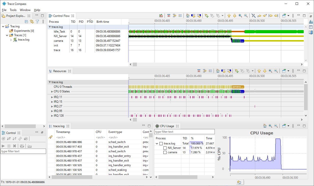
23. Debug logging
This section explains the debug logging features provided by SDK.
23.1. syslog feature
Debug logging output is using the system log (syslog) function. The syslog has three log levels, Error, Warnings, and Informational.
You can select whether or not to output logs for each module such as subsystem or driver by configuration.
To enable the debug logging function, open menuconfig from the previously configured state.
cd spresense/sdk tools/config.py -m or make menuconfig
In the menu of Build Setup → Debug Options, Enable Enable Debug Features.
The following menu will be displayed.
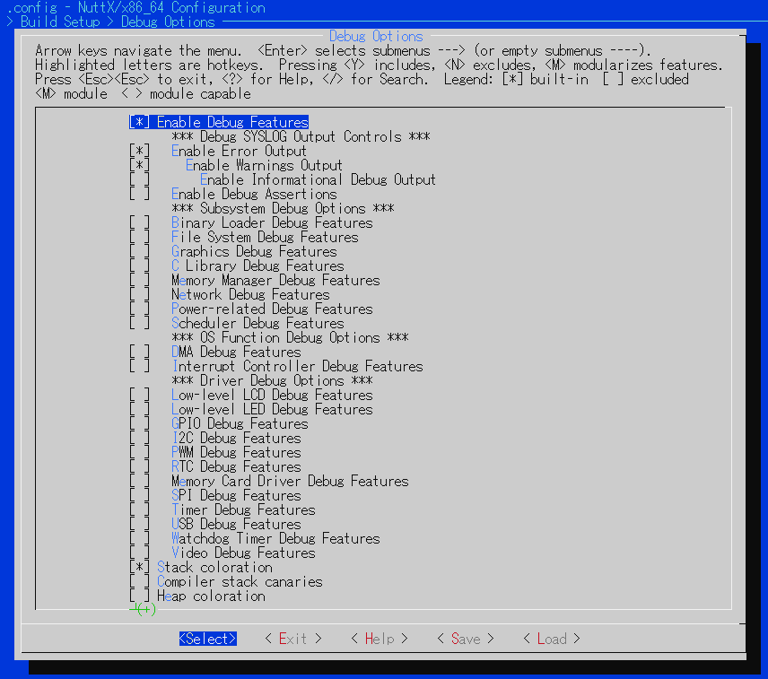
The *** Debug SYSLOG Output Controls *** determines the overall log output level.
The log level selection is nested, and, for example, if you enable Informational, you must also enable Error and Warnings.
*** Debug SYSLOG Output Controls ***
[] Enable Error Output
[] Enable Warnings Output
[] Enable Informational OutputThe relationship between the log output function and the CONFIG name is shown as below.
Each log output function will output the log when the corresponding CONFIG is enabled.
For example, when CONFIG_DEBUG_INFO=y, the log using the _info() function will be output.
If you disable it like CONFIG_DEBUG_INFO=n, _info() will not be compiled and the log will not output.
| log function | CONFIG name |
|---|---|
_err() |
CONFIG_DEBUG_ERROR |
_warn() |
CONFIG_DEBUG_WARN |
_info() |
CONFIG_DEBUG_INFO |
The NuttX common log output functions for each module are defined in nuttx/include/debug.h. Each module has its own log function with a prefix. For example, the log functions for the filesystem have a prefix of f as below.
[*] File System Debug Features
[ ] File System Error Output
[ ] File System Warnings Output
[ ] File System Informational Output| log function | CONFIG name |
|---|---|
ferr() |
CONFIG_DEBUG_FS_ERROR |
fwarn() |
CONFIG_DEBUG_FS_WARN |
finfo() |
CONFIG_DEBUG_FS_INFO |
In addition to the common definitions in nuttx/include/debug.h, there are also configurations for drivers and SDK modules.
The CONFIG names of the main modules and debug log functions used in the SDK environment are listed below.
To enable debug logging for the module, please search for the following CONFIG names on menuconfig.
| Module | CONFIG name |
|---|---|
SCU driver |
CONFIG_CXD56_SCU_DEBUG |
modem driver |
CONFIG_MODEM_ALT1250_DEBUG |
HostIF driver |
CONFIG_CXD56_HOSTIF_DEBUG |
GNSS driver |
CONFIG_CXD56_GNSS_DEBUG_FEATURE |
ASMP |
CONFIG_ASMP_DEBUG_FEATURE |
Audio |
CONFIG_AUDIOUTILS_{EVENT,STATE, DETAIL}LOG |
mbedTLS_stub |
CONFIG_LTE_NET_MBEDTLS_{ERROR,DEBUG}_MSG |
MPCOMM |
CONFIG_MPCOMM_DEBUG_FEATURE |
Sensor Manager |
CONFIG_SENSING_MANAGER_DEBUG_FEATURE |
Step Counter |
CONFIG_SENSING_STEPCOUNTER_DEBUG_FEATURE |
xmodem |
CONFIG_DEBUG_XMODEM |
Try to use the debug log function effectively when you want to check the detailed behavior or debug individual modules.
When you use both syslog and printf, the printf output is buffered and displayed, so the order of printf and syslog output may be swapped.
|
23.2. RAM log
The syslog mentioned above normally outputs logs to a serial console such as UART. However, by changing the configuration, it is possible to switch the output destination to another device. This section explains how to output the log to a buffer on the RAM memory (hereinafter called RAM buffer).
Outputting to the RAM buffer reduces the speed overhead of accessing the UART.
The logs accumulated in the RAM buffer can be output to the console by the dmesg command.
23.2.1. How to build
This is the build procedure via the command line.
When you use IDE, refer to the explanation of the following configuration.
-
Change directory to
sdkIf you do source
build-env.shscript, you can use the tab completion of theconfig.pytool.cd spresense/sdk source tools/build-env.sh
-
SDK configuration and building
Execute the configuration by specifying
feature/ramlogorfeature/ramlog_circularas an argument ofconfig.py. As for theramlogconfiguration, choose appropriate configuration for your application.defconfig Description feature/ramlog
Logging will continue until the RAM buffer is full. When it is full, the log buffering stops. Running the
dmesgcommand will empty the buffer and resume buffering.feature/ramlog_circular
The RAM buffer has a ring buffer structure and is always overwritten and updated with the latest log.
tools/config.py feature/ramlog or tools/config.py feature/ramlog_circular
If you want to change the size of the RAM buffer, change the value of
CONFIG_RAMLOG_BUFSIZEwithmenuconfig.If the build is successful, a
nuttx.spkfile will be created under thesdkdirectory.make -
Flashing
nuttx.spkinto Spresense boardIn this case, the serial port is
/dev/ttyUSB0, and the baudrate of the uploading speed is500000bps. Please change according to your environment.tools/flash.sh -c /dev/ttyUSB0 -b 500000 nuttx.spk
23.2.2. Operation check
-
Open the serial terminal
This is an example of using a minicom terminal with
/dev/ttyUSB0as the serial port and115200for the baudrate.minicom -D /dev/ttyUSB0 -b 115200 -
Type
dmesgcommand on NuttShell prompt -
Type
dmesgcommand on NuttShell prompt, and output log with timestamp in the RAM buffer to the console.
The following is an example of the log when filesystem detail logging is enabled.nsh> dmesg [ 51.161556] smart_ioctl: Entry [ 51.161648] smart_readsector: Entry [ 51.161709] cxd56_bread: bread: 00009000 (1 blocks) [ 51.163510] smart_ioctl: Entry [ 51.163571] smart_readsector: Entry [ 51.163662] cxd56_bread: bread: 00009000 (1 blocks) [ 51.165463] smart_ioctl: Entry [ 51.165524] smart_readsector: Entry [ 51.165615] cxd56_bread: bread: 00009000 (1 blocks) [ 51.167446] smart_ioctl: Entry [ 51.167507] smart_readsector: Entry [ 51.167599] cxd56_bread: bread: 00009000 (1 blocks)
23.3. crash dump
It supports saving a log of crashes caused by assert or Hard fault (hereinafter called crash dump) to a file.
This feature is available by using the feature/crashdump configuration.
In the beginning, we will briefly explain the steps to check the operation, and then explain the source code.
23.3.1. How to build
This is the build procedure via the command line.
When you use IDE, refer to the explanation of the following configuration.
-
Change directory to
sdkIf you do source
build-env.shscript, you can use the tab completion of theconfig.pytool.cd spresense/sdk source tools/build-env.sh
-
SDK configuration and building
Execute the configuration by specifying
feature/crashdumpas an argument ofconfig.py. We also addexamples/watchdogfor the purpose of generatingcrash.tools/config.py feature/crashdump examples/watchdogIf the build is successful, a
nuttx.spkfile will be created under thesdkdirectory.make -
Flashing
nuttx.spkinto Spresense boardIn this case, the serial port is
/dev/ttyUSB0, and the baudrate of the uploading speed is500000bps. Please change according to your environment.tools/flash.sh -c /dev/ttyUSB0 -b 500000 nuttx.spk
23.3.2. Operation check
-
Open the serial terminal
This is an example of using a minicom terminal with
/dev/ttyUSB0as the serial port and115200for the baudrate.minicom -D /dev/ttyUSB0 -b 115200 -
Running the
wdogcommand on NuttShell will result in aHard faultand then reboot.nsh> wdog ping elapsed=0 ping elapsed=496 (snip) up_assert: Assertion failed at file:irq/irq_unexpectedisr.c line: 50 task: wdog up_registerdump: R0: 00000008 00000001 2d02e7f8 00000008 2d02e7f8 2d02e7f8 2d02e7f8 00000001 up_registerdump: R8: 000f4240 0d026575 00000020 2d035bf4 0000001d 2d035b08 0d006601 0d006604 (snip) up_stackdump: 2d035c60: 00000000 0d00421d 00000000 00000000 2d035c78 00000000 676f6477 deadbe00 up_taskdump: Idle Task: PID=0 Stack Used=468 of 1024 up_taskdump: hpwork: PID=1 Stack Used=324 of 2008 up_taskdump: lpwork: PID=2 Stack Used=332 of 2008 up_taskdump: lpwork: PID=3 Stack Used=332 of 2008 up_taskdump: lpwork: PID=4 Stack Used=332 of 2008 up_taskdump: cxd56_pm_task: PID=6 Stack Used=400 of 976 up_taskdump: init: PID=7 Stack Used=944 of 8152 up_taskdump: wdog: PID=8 Stack Used=636 of 2008 up_taskdump: wdog: PID=8 Stack Used=636 of 2008 NuttShell (NSH) NuttX-10.1.0 nsh>
-
After reboot, you can run the
logdump crashcommand on NuttShell to display thecrash dumpinformation when the watchdog timer expired.nsh> logdump crash === Dump crash at 0x04408200 (1020 bytes) date: Jan 01 00:00:12 1970 file: irq/irq_unexpectedisr.c line: 50 task: wdog pid: 8 user sp: 2d035b08 stack base: 2d035c70 stack size: 000007d8 int sp: 2d027338 stack base: 2d0273b0 stack size: 00000800 regs: S0: 00000000 00000000 00000000 00000000 00000000 00000000 00000000 00000000 S8: 00000000 00000000 00000000 00000000 00000000 00000000 00000000 00000000 S16: 00000000 00000000 00000000 00000000 00000000 00000000 00000000 00000000 S24: 00000000 00000000 00000000 00000000 00000000 00000000 00000000 00000000 FPSCR: 00000000 R0: 00000008 00000001 2d02e7f8 00000008 2d02e7f8 2d02e7f8 2d02e7f8 00000001 R8: 000f4240 0d026575 00000020 2d035bf4 0000001d 2d035b08 0d006601 0d006604 xPSR: 61000000 BASEPRI: 000000e0 EXC_RETURN: ffffffe9 interrupt stack: 00000000 00000000 00000000 00000000 00000000 00000000 00000000 00000000 00000000 00000000 00000000 00000000 0000000d 676f6477 0d000333 00000001 2d02e7f8 2d02e7f8 2d035a34 000000e0 0d00194d 000000e0 0d003413 0d003439 0d00344d 00000080 0d006549 2d035bf4 00000020 0d026575 000f4240 00000000 00000002 2d035a34 2d029a84 2d02e5b0 0d006539 0d006604 0d006601 2d035b08 0000001d 2d035bf4 00000000 000000e0 0d008279 0d021d7c 2d035c70 2d029a84 2d035b08 2d027338 0d00d619 04408200 04408200 044085fc 07249e03 0000000c 0d005aab 0d021d7c 2d027338 04408200 04408200 ffffffff 0d005383 2d027308 00000032 00000032 000003fc 2d027338 2d02e5b0 2d027338 0d011cab 000001e0 0000001e 0d006949 00000030 0d006949 0d00fd9d 2d0273b0 0d00fd57 2d0273b0 2d02e5b0 00000000 2d029ab8 00000080 0d00809d 2d0272d4 user stack: 2d035bf4 2d035bf0 0d01db85 0d026560 00000000 0d026575 000f4240 00000000 00001b54 0d026575 2d02e7f8 ffffffff 00000000 2d035ba8 0d005897 00000000 2d02e5b0 00000014 00000000 00000000 00000000 0d026576 00000000 00000000 0d006977 00000000 2d035bb8 0d01dba1 0d01dbaf 00000020 2d035bb8 2d035bf4 2002e7f8 00000020 0d01e4f5 00000000 00001b54 2d02e7f8 00000020 0d01dba1 0d01d9e5 2d02e7f8 2d02e7f8 2d035b37 00000000 00000000 00000000 00000000 00000000 00000000 00000000 00000000 00000000 00000000 00000000 00000000 00000000 00000000 00000000 00000000 00000000 00000000 61000000 0d006604 0d006601 0000001d 00000008 2d02e7f8 00000001 00000008 00000000 00000000 00000000 00000000 00000000 00000000 00000000 00000000 00000000 00000000 00000000 00000000 00000000 00000000 00000000 00000000 No such file: /mnt/spif/crash.log
-
You can also save the RAW binary data of a
crash dumpto/mnt/spif/crash.logby running thelogsavecommand on NuttShell. The saved binary file can be decoded and displayed later by using thelogdump crashcommand.nsh> logsave Save at 0x04408200 (1020 bytes) into /mnt/spif/crash.log
23.3.3. Code explanation
In NuttX, the board_crashdump() function is called when a hard fault occurs.
A board_crashdump() function is implemented in nuttx/boards/arm/cxd56xx/common/src/cxd56_crashdump.c.
Call the up_backuplog_alloc() function to allocate memory from the backup SRAM with the keyword name "crash".
#ifdef CONFIG_CXD56_BACKUPLOG
pdump = up_backuplog_alloc("crash", sizeof(fullcontext_t));
#elseWrite crash dump information to the allocated backup SRAM memory.
At the end of the board_crashdump() function, call the board_reset_on_crash() function to reboot.
#if defined(CONFIG_CXD56_RESET_ON_CRASH)
board_reset_on_crash();
#endifAs a point of interest, the contents stored in the backup SRAM will be kept unless the power is turned off.
A crash dump makes use of this mechanism. It temporarily stores the information in the backup SRAM and refers to it after reboot.
By referring to the information after the reboot, it avoids problems such as not being able to write to files when a crash occurs.
Next, it explains how to get a crash dump after a reboot.
logdump command is implemented in sdk/system/logdump/logdump.c.
Get the address and size of the crash dump stored with the keyword name "crash" as the command argument by using up_backuplog_region() function.
/* Dump from memory */
up_backuplog_region(name, &addr, &size);Pass the address and size to the logdump_sub() function to decode and display the crash dump information that had been saved to the backup SRAM.
printf("=== Dump %s at 0x%08x (%d bytes)\n", name, (uint32_t)addr, size);
logdump_sub(name, addr, size);To save the RAW binary data of crash dump to a file, use the logsave command. A logsave command is implemented in sdk/system/logsave/logsave.c.
The up_backuplog_entry() function retrieves the keyword name "crash", address, and size information stored in the backup SRAM.
/* Get a log entry */
ret = up_backuplog_entry(name, &addr, &size);Save the information stored in the backup SRAM as a file to the destination specified by CONFIG_SYSTEM_LOGSAVE_MOUNTPOINT.
The default of CONFIG_SYSTEM_LOGSAVE_MOUNTPOINT is "/mnt/spif", and the RAW binary data of crash dump is saved to "/mnt/spif/crash.log".
Because this file is always appended, you can save the crash history by running the logsave command at start-up. As described above, the data saved in this file can be decoded and displayed later by the logdump command.
Finally, besides crash dump, it is also possible to save some information in the backup SRAM and refer to it after rebooting.
Please refer to the source code implemented here.
24. How to analyze the call stack log
This section explains how to use the script callstack.py to analyze the call stack from the dump log which is a log when a program asserting occurs on Spresense.
24.1. About callstack.py
When running a program with Spresense, the following dump log may be displayed due to a problem with the program.
arm_hardfault: Hard Fault escalation:
arm_hardfault: PANIC!!! Hard Fault!:arm_hardfault: IRQ: 3 regs: 0x2d035d2c
arm_hardfault: BASEPRI: 000000e0 PRIMASK: 00000000 IPSR: 00000003 CONTROL: 00000000
arm_hardfault: CFSR: 00040000 HFSR: 40000000 DFSR: 00000000 BFAR: e000ed38 AFSR: 00000000
arm_hardfault: Hard Fault Reason:
up_assert: Assertion failed at file:armv7-m/arm_hardfault.c line: 173 task: hello
arm_registerdump: R0: 2d0284c8 R1: 0d0258aa R2: 2d035e18 R3: 00000028
arm_registerdump: R4: 0d012481 R5: 2d0284c8 R6: 0d0258aa FP: 2d035e18
arm_registerdump: R8: 00000028 SB: 2d02e930 SL: 2d035e18 R11: 00000000
arm_registerdump: IP: 2d02e930 SP: 2d035e00 LR: 2d035e18 PC: 00000000
arm_registerdump: xPSR: ffffffe9 BASEPRI: 000000e0 CONTROL: 00000000
arm_registerdump: EXC_RETURN: ffffffe9
...
arm_dump_stack: User Stack:
arm_dump_stack: sp: 2d035e00
arm_dump_stack: base: 2d035688
arm_dump_stack: size: 000007d8
arm_stackdump: 2d035e00: 2d035e18 00000028 2d02e930 2d035e18 00000000 ffffffe9 00000000 00000000
arm_stackdump: 2d035e20: 00000000 00000000 00000000 00000000 00000000 00000000 00000000 00000000
arm_stackdump: 2d035e40: 00000000 00000000 00000000 2d035e00 000000e0 0d012481 2d0284c8 0d0258aa
arm_showtasks: PID PRI STACK USED FILLED COMMAND
arm_showtasks: ---- ---- 2048 456 22.2% irq
arm_dump_task: 0 0 1000 396 39.6% Idle Task
arm_dump_task: 1 224 1992 276 13.8% hpwork 0x2d028720
arm_dump_task: 2 100 1992 276 13.8% lpwork 0x2d028730
arm_dump_task: 3 100 1992 276 13.8% lpwork 0x2d028730
arm_dump_task: 4 100 1992 276 13.8% lpwork 0x2d028730
arm_dump_task: 13 100 2008 532 26.4% hello
arm_dump_task: 6 200 976 464 47.5% cxd56_pm_task
arm_dump_task: 7 100 8144 1076 13.2% spresense_mainBy parsing this log message with callstack.py, you can extract it as a call stack as shown below.
[0d006eb5] vsyslog + 0x15
[0d005d17] _assert + 0x7
[0d001b03] arm_hardfault + 0xa7
[0d0258aa] g_builtins + 0x76
[0d00365f] irq_dispatch + 0x17
[0d001a49] arm_doirq + 0x1d
[0d012481] hello_main + 0x1
[0d00030d] exception_common + 0x35
[0d012481] hello_main + 0x1
[0d0258aa] g_builtins + 0x76
24.2. How to use callstack.py
Use the following binary and texts information to extract the call stack from the dump log.
-
Spresense operation log including dump log(
log.txt) -
MAP file generated when building the running program(
System.map)
Using the above file, use the following command to display the call stack.
$ cd sdk
$ ../nuttx/tools/callstack.py System.map log.txtThe following is an example of the analysis result when assert is intentionally added to the examples/hello sample.
$ ../nuttx/tools/callstack.py System.map log.txt
NuttShell (NSH) NuttX-11.0.0
nsh> hello
Hello, World!!
up_assert: Assertion failed at file:hello_main.c line: 40 task: hello
arm_hardfault: Hard Fault escalation:
arm_hardfault: PANIC!!! Hard Fault!:arm_hardfault: IRQ: 3 regs: 0x2d035d2c
arm_hardfault: BASEPRI: 000000e0 PRIMASK: 00000000 IPSR: 00000003 CONTROL: 00000000
arm_hardfault: CFSR: 00040000 HFSR: 40000000 DFSR: 00000000 BFAR: e000ed38 AFSR: 00000000
arm_hardfault: Hard Fault Reason:
up_assert: Assertion failed at file:armv7-m/arm_hardfault.c line: 173 task: hello
arm_registerdump: R0: 2d0284c8 R1: 0d0258aa R2: 2d035e18 R3: 00000028
arm_registerdump: R4: 0d012481 R5: 2d0284c8 R6: 0d0258aa FP: 2d035e18
arm_registerdump: R8: 00000028 SB: 2d02e930 SL: 2d035e18 R11: 00000000
arm_registerdump: IP: 2d02e930 SP: 2d035e00 LR: 2d035e18 PC: 00000000
arm_registerdump: xPSR: ffffffe9 BASEPRI: 000000e0 CONTROL: 00000000
arm_registerdump: EXC_RETURN: ffffffe9
arm_dump_stack: IRQ Stack:
arm_dump_stack: sp: 2d027a50
arm_dump_stack: base: 2d0272c0
arm_dump_stack: size: 00000800
arm_stackdump: 2d027a40: 00000001 00000000 00000000 0d006eb5 40000000 00000003 2d035d2c 00040000
arm_stackdump: 2d027a60: 00000028 2d02e930 2d035e18 0d005d17 00000080 0d001b03 40000000 00000000
arm_stackdump: 2d027a80: e000ed38 00000000 00000000 00000000 2d0284c8 0d0258aa 2d035e18 0d00365f
arm_stackdump: 2d027aa0: 00000000 0d001a49 00000003 00000003 2d035e00 0d012481 2d0284c8 0d00030d
arm_dump_stack: User Stack:
arm_dump_stack: sp: 2d035e00
arm_dump_stack: base: 2d035688
arm_dump_stack: size: 000007d8
arm_stackdump: 2d035e00: 2d035e18 00000028 2d02e930 2d035e18 00000000 ffffffe9 00000000 00000000
arm_stackdump: 2d035e20: 00000000 00000000 00000000 00000000 00000000 00000000 00000000 00000000
arm_stackdump: 2d035e40: 00000000 00000000 00000000 2d035e00 000000e0 0d012481 2d0284c8 0d0258aa
arm_showtasks: PID PRI STACK USED FILLED COMMAND
arm_showtasks: ---- ---- 2048 456 22.2% irq
arm_dump_task: 0 0 1000 396 39.6% Idle Task
arm_dump_task: 1 224 1992 276 13.8% hpwork 0x2d028720
arm_dump_task: 2 100 1992 276 13.8% lpwork 0x2d028730
arm_dump_task: 3 100 1992 276 13.8% lpwork 0x2d028730
arm_dump_task: 4 100 1992 276 13.8% lpwork 0x2d028730
arm_dump_task: 13 100 2008 532 26.4% hello
arm_dump_task: 6 200 976 464 47.5% cxd56_pm_task
arm_dump_task: 7 100 8144 928 11.3% spresense_main
----------------- callstack -----------------
[0d006eb5] vsyslog + 0x15
[0d005d17] _assert + 0x7
[0d001b03] arm_hardfault + 0xa7
[0d0258aa] g_builtins + 0x76
[0d00365f] irq_dispatch + 0x17
[0d001a49] arm_doirq + 0x1d
[0d012481] hello_main + 0x1
[0d00030d] exception_common + 0x35
[0d012481] hello_main + 0x1
[0d0258aa] g_builtins + 0x76From this log, you can see that [0d012481] hello_main + 0x1 is the last call from call stack information, which is asserted near the beginning of the hello_main function.
25. backtrace
This section describes how to enable the backtrace feature, how to get the call tree from the stack dump log, and how to use the dump_stack() and backtrace() functions.
To use this feature, please add feature/backtrace or feature/debug to your SDK configuration.
25.1. How to get call tree
If you have added feature/backtrace or feature/debug to the SDK configuration, the following stack dump log is displayed when a Hard Fault occurs.
arm_hardfault: Hard Fault escalation:
arm_hardfault: PANIC!!! Hard Fault!:arm_hardfault: IRQ: 3 regs: 0x2d044e14
arm_hardfault: BASEPRI: 000000e0 PRIMASK: 00000000 IPSR: 00000003 CONTROL: 00000000
arm_hardfault: CFSR: 00008200 HFSR: 40000000 DFSR: 00000000 BFAR: 05000000 AFSR: 00000000
arm_hardfault: Hard Fault Reason:
up_assert: Assertion failed at file:armv7-m/arm_hardfault.c line: 173 task: spresense_main
backtrace| 7: 0x0d029de6 0x0d01db40 0x0d01a964 0x0d01b43a 0x0d01deea 0x0d01e842 0x0d01a06a 0x0d0062d8
backtrace| 7: 0x0d0048ba
arm_registerdump: R0: 05000000 R1: 00000010 R2: 2d044ec4 R3: 00000000
arm_registerdump: R4: 2d03de70 R5: 2d03de70 R6: 00000000 FP: 05000000
arm_registerdump: R8: 00000001 SB: 05000000 SL: 00000000 R11: 0d033421
arm_registerdump: IP: 00000000 SP: 2d044ee8 LR: 0d0070b9 PC: 0d01db40
arm_registerdump: xPSR: 81000000 BASEPRI: 000000e0 CONTROL: 00000000
arm_registerdump: EXC_RETURN: ffffffe9
arm_dump_stack: IRQ Stack:
arm_dump_stack: sp: 2d036a88
arm_dump_stack: base: 2d0362f8
arm_dump_stack: size: 00000800
arm_stackdump: 2d036a80: 0d01db40 0d007339 40000000 00000003 2d044e14 00008200 00000001 05000000
arm_stackdump: 2d036aa0: 00000000 0d0061bb 00000080 0d001d73 40000000 00000000 05000000 00000000
arm_stackdump: 2d036ac0: 0d0004d1 00000000 2d037500 00000000 05000000 0d003aa7 00000000 0d001cb1
arm_dump_stack: User Stack:
arm_dump_stack: sp: 2d044ee8
arm_dump_stack: base: 2d043110
arm_dump_stack: size: 00001fd0
arm_stackdump: 2d044ee0: 00000000 0d01db0d 2d03de70 00000000 2d044f78 2d03de70 00000000 2d044f78
arm_stackdump: 2d044f00: ffffffff 00000002 00000000 0d0333b4 00000000 0d01a969 00000000 ffffffe9
arm_stackdump: 2d044f20: 00000000 00000000 00000000 00000000 00000000 00000000 00000000 00000000
arm_stackdump: 2d044f40: 00000000 2d03de70 2d03e2dc 00000002 00000000 00000000 00000000 0d0333b4
arm_stackdump: 2d044f60: 00000000 0d01b43f 00000000 0d0003cb 2d03e2e8 00000000 2d03e2dc 2d03e2df
arm_stackdump: 2d044f80: 00000000 00000000 00000000 00000000 00000000 00000000 00000000 00000000
arm_stackdump: 2d044fa0: 00000000 00000000 00000000 00000000 00000000 00000000 00000000 00000000
arm_stackdump: 2d044fc0: 00000000 00000000 00000000 00000000 00000000 00000000 00000000 00000000
arm_stackdump: 2d044fe0: 00000000 00000000 00000000 00000000 00000000 00000000 00000000 00000000
arm_stackdump: 2d045000: 00000000 00000000 00000000 00000000 00000000 00000000 00000000 00000000
arm_stackdump: 2d045020: 00000000 00000000 00000000 00000000 00000000 00000000 00000000 00000000
arm_stackdump: 2d045040: 00000000 00000000 00000000 00000000 2d03e2dc 2d03de70 2d042e68 2d03e2dc
arm_stackdump: 2d045060: 0d0333a6 00000001 00000000 00000000 00000000 0d01deef 2d03de70 00000001
arm_stackdump: 2d045080: 2d03de70 2d0430f8 00000000 00000000 00000000 0d01e847 2d0430f8 00000001
arm_stackdump: 2d0450a0: 00000001 0d01a06f 00000000 00000000 0d00cdad 00000064 00000000 0d00cdad
arm_stackdump: 2d0450c0: 00000000 0d0062db 2d0430f8 00000001 2d0430f8 0d0048bf 00000000 00000000
arm_showtasks: PID PRI STACK USED FILLED COMMAND
arm_showtasks: ---- ---- 2048 592 28.9% irq
arm_dump_task: 0 0 1000 380 38.0% Idle Task
arm_dump_task: 1 224 1992 588 29.5% hpwork 0x2d037758
arm_dump_task: 2 100 1992 276 13.8% lpwork 0x2d037768
arm_dump_task: 3 100 1992 276 13.8% lpwork 0x2d037768
arm_dump_task: 4 100 1992 276 13.8% lpwork 0x2d037768
arm_dump_task: 6 200 976 464 47.5% cxd56_pm_task
arm_dump_task: 7 100 8144 716 8.7% spresense_main
backtrace| 0: 0x0d00797e 0x0d00399e 0x0d003996 0x0d0002a0
backtrace| 1: 0x0d007efa 0x0d00400e 0x0d00400a 0x0d00402a 0x0d004a7a 0x0d0048a6
backtrace| 2: 0x0d007efa 0x0d00400e 0x0d00400a 0x0d00402a 0x0d004a7a 0x0d0048a6
backtrace| 3: 0x0d007efa 0x0d00400e 0x0d00400a 0x0d00402a 0x0d004a7a 0x0d0048a6
backtrace| 4: 0x0d007efa 0x0d00400e 0x0d00400a 0x0d00402a 0x0d004a7a 0x0d0048a6
backtrace| 6: 0x0d007efa 0x0d003d7c 0x0d003d78 0x0d003cea 0x0d001926 0x0d0062d8 0x0d0048ba
backtrace| 7: 0x0d029de6 0x0d03459b 0x0d003d75 0x0d01db40 0x0d01a964 0x0d01b43a 0x0d01deea 0x0d01e842
backtrace| 7: 0x0d01a06a 0x0d0062d8 0x0d0048baThe backtrace line displays the call stack addresses for each PID number.
backtrace| PID number: call stack addressesUsing the arm-none-eabi-addr2line command, you can get the source code of the call tree (file name and line number) by entering the ELF file of the built image nuttx and the addresses shown in the backtrace line.
$ arm-none-eabi-addr2line -e nuttx 0x0d029de6 0x0d01db40 0x0d01a964 0x0d01b43a 0x0d01deea 0x0d01e842 0x0d01a06a 0x0d0062d8 0x0d0048ba
/home/username/spresense/nuttx/arch/arm/src/common/arm_backtrace_thumb.c:485
/home/username/spresense/sdk/apps/nshlib/nsh_dbgcmds.c:255
/home/username/spresense/sdk/apps/nshlib/nsh_parse.c:741
/home/username/spresense/sdk/apps/nshlib/nsh_parse.c:2592
/home/username/spresense/sdk/apps/nshlib/nsh_session.c:217
/home/username/spresense/sdk/apps/nshlib/nsh_consolemain.c:106
/home/username/spresense/sdk/apps/system/nsh/nsh_main.c:153
/home/username/spresense/nuttx/libs/libc/sched/task_startup.c:70
/home/username/spresense/nuttx/sched/task/task_start.c:13425.2. How to use dump_stack() function
By including execinfo.h in the source code and adding the dump_stack() function
#include <execinfo.h>
dump_stack();You can display backtrace lines on the log.
backtrace|21: 0x0d01f7ba 0x0d010440 0x0d0003e6 0x0d005794 0x0d0184c0 0x0d0184d0 0x0d003bba 0x0d006abe
backtrace|21: 0x0d01227c 0x0d005d90 0x0d004372As mentioned above, you can use the arm-none-eabi-addr2line command to print the call tree to the point where you inserted dump_stack().
$ arm-none-eabi-addr2line -e nuttx 0x0d01f7ba 0x0d010440 0x0d0003e6 0x0d005794 0x0d0184c0 0x0d0184d0 0x0d003bba 0x0d006abe 0x0d01227c 0x0d005d90 0x0d004372
/home/username/spresense/nuttx/arch/arm/src/common/arm_backtrace_thumb.c:485
/home/username/spresense/nuttx/libs/libc/sched/sched_dumpstack.c:69
/home/username/spresense/nuttx/arch/arm/src/chip/cxd56_serial.c:1007
/home/username/spresense/nuttx/drivers/serial/serial.c:1266
/home/username/spresense/nuttx/fs/vfs/fs_write.c:138
/home/username/spresense/nuttx/fs/vfs/fs_write.c:202
/home/username/spresense/nuttx/sched/semaphore/sem_post.c:224
/home/username/spresense/nuttx/include/nuttx/mutex.h:259
/home/username/spresense/sdk/apps/examples/hello/hello_main.c:40
/home/username/spresense/nuttx/libs/libc/sched/task_startup.c:70
/home/username/spresense/nuttx/sched/task/task_start.c:134You can also use the backtrace() function in the same way as in Linux manual page.
The backtrace_symbols() and backtrace_symbols_fd() functions can also be called, but it cannot output the symbol information.
|
26. Using GNSS RAM memory
In use cases where the Spresense built-in GNSS feature is not used, it is provided to use 640KByte of GNSS RAM as general-purpose memory for the user application.
To use this feature, please update the bootloader to SDKv3.2.0 or later by referring to Flashing bootloader.
26.1. Restrictions
The following restrictions apply to the use of GNSS RAM.
-
Cannot be used simultaneously with the built-in GNSS feature
-
If the built-in GNSS firmware is running, accessing GNSS RAM from the application will result in a Hardfault error.
-
This is exclusive with the built-in GNSS feature, so if you are using a GNSS Add-on board, you are not subject to this restriction.
-
-
Slow memory access speed
-
Performance is reduced to 1/8 or less of the RAM normally used by the application.
-
Use in applications where slow memory access is acceptable.
-
-
Cannot be used as a buffer directly accessed by hardware DMA
-
Not available for Camera (CISIF) buffer
-
Not available for Audio buffer
-
26.2. How to locate codes and data into GNSS RAM
Any code or data can be located into GNSS RAM by adding GNSSRAM_CODE, GNSSRAM_DATA and GNSSRAM_BSS to the source code.
The user builds a program containing these keywords and generates nuttx.spk.
The actual location into GNSS RAM is done by the bootloader at boot time.
The example code is shown below.
#include <arch/chip/gnssram.h> (1)
static const int g_alloc_sizes[NTEST_ALLOCS] GNSSRAM_DATA = (2)
{
1024, 12, 962, 5692, 10254, 111, 9932, 601,
222, 2746, 3, 124321, 68, 776, 6750, 852,
4732, 28, 901, 480, 5011, 1536, 2011, 81647,
646, 1646, 69179, 194, 2590, 7, 969, 70
};
static void *g_allocs[NTEST_ALLOCS] GNSSRAM_BSS; (3)
static GNSSRAM_CODE void function(void) (4)
{
}| 1 | Include gnssram.h |
| 2 | By appending GNSSRAM_DATA to the data with initial value (data), it can be located into the data section on the GNSS RAM. |
| 3 | By appending GNSSRAM_BSS to the data without initial value (bss), it can be located into the bss section on the GNSS RAM. |
| 4 | By appending GNSSRAM_CODE to the function (text), it can be located into the text section on the GNSS RAM. |
If you want to locate not the function or variable but library (archive) or object file into GNSS RAM, edit the link script file directly.
An example of modifying a link script file is shown below.
/* GNSS memory */
.gnssram.text : {
_sgnsstext = ABSOLUTE(.);
/* Possible to locate text of any object file.
* *libxxx.a:*.o(.text .text.*)
* *libxxx.a:*.o(.rodata .rodata.*)
*/
*libapps.a:*.o(.text .text.*) (1)
*libapps.a:*.o(.rodata .rodata.*)
} > gnssram
.gnssram.data . : ALIGN(4) {
/* Possible to locate data of any object file.
* *libxxx.a:*.o(.data .data.*)
*/
*libapps.a:*.o(.data .data.*) (2)
} > gnssram
.gnssram.bss . (NOLOAD) : {
. = ALIGN(4);
_gnssramsbss = ABSOLUTE(.);
/* Possible to locate bss of any object file.
* *libxxx.a:*.o(.bss .bss.*)
* *libxxx.a:*.o(COMMON)
*/
*libapps.a:*.o(.bss .bss.*) (3)
*libapps.a:*.o(COMMON)
} > gnssram| 1 | text and rodata of all objects in libapps.a can be located into the text section on GNSS RAM. |
| 2 | data of all objects in libapps.a can be located into the data section on GNSS RAM. |
| 3 | bss of all objects in libapps.a can be located into the bss section on GNSS RAM. |
By changing the description here, it is possible to locate only specific object files into GNSS RAM. For more information, please refer to the GNU ld documentation.
26.3. How to use GNSS RAM as heap memory
By calling the up_gnssram_initialize() function, GNSS RAM memory can be used as a heap area.
If code and data are located into GNSS RAM as mentioned above, free memory excluding them is allocated to the heap area.
#include <arch/chip/gnssram.h> (1)
up_gnssram_initialize(); (2)| 1 | Include gnssram.h |
| 2 | Call an initialization function to use GNSS RAM as the heap area. |
A set of dedicated memory allocation functions is provided to use this heap area. Instead of malloc/free, the following functions can be called to use the heap area on GNSS RAM.
#include <arch/chip/gnssram.h>
void *up_gnssram_malloc(size_t size);
void *up_gnssram_calloc(size_t n, size_t elem_size);
void *up_gnssram_realloc(void *ptr, size_t size);
void *up_gnssram_zalloc(size_t size);
void up_gnssram_free(void *mem);
void *up_gnssram_memalign(size_t alignment, size_t size);
struct mallinfo up_gnssram_mallinfo(void);26.4. How to manage GNSS RAM yourself
extern int cxd56_gnssram_clock_enable(void); (1)
cxd56_gnssram_clock_enable(); (2)| 1 | Add a prototype declaration to suppress compiler warnings. |
| 2 | Call low-level API to use GNSS RAM. |
By executing this function, the GNSS RAM (640KByte) memory can be freely accessed. The address space from the application CPU is 0x09000000 ~ 0x090a0000.